Jolt manuals and documents

Documents

Jolt Replica User manual
Jolt User Newsletter
DEMON software manual
(this manual has an alternative listing of the TIM 6530-004 monitor)

Alter memory or registers

Sample session

 *  7052 B0 00 FF 00 FF
.M  0200 00 00 00 00 00 00 00 00
.:  0200 33 44 55
.M  0200 33 44 55 00 00 00 00 00
.R  7052 B0 00 FF 00 FF
.:  3455 55 55 55 55 55
.R  3455 55 55 55 55 55
.M  00F6 55 34 55 55 55 55 55 02
.M  7000 85 F9 A9 23 D0 55 A9 16
.:  7000 77?
.?
.

The ‘:’ command reacts different upon previous actions:

  • if the previous command was M, the current address types in with M is printed and bytes can be typed in that will be placed at the current PC. The current address is incremented and the next byte can be entered, till maximum 8 are entered 85
  • if the previous command was R the program counter has to be typed and the 5 registers PS A X Y Z (or less by pressing ENTER).
  • after a ‘:’ command, the next ‘:’ will behave the same as following the M command

Note the current address and the Program Counter are not the same. The GO command requires the Program Counter to be set to the desired address.

0282   70E0             ;
0283   70E0             ;  READ AND STORE BYTE.  NO STORE IF SPACE OR RCNT=0.
0284   70E0             ;
0285   70E0 20 B3 73    BYTE   JSR RDOB          ; CHAR IN A, CY=0 IF SP
0286   70E3 90 10              BCC BY3           ; SPACE
0287   70E5             ;
0288   70E5 A2 00              LDX #0            ; STORE BYTE
0289   70E7 81 EE              STA (TMP0,X)
0290   70E9             ;
0291   70E9 C1 EE              CMP (TMP0,X)      ; TEST FOR VALID WRITE (RAM)
0292   70EB F0 05              BEQ BY2
0293   70ED 68                 PLA               ; ERR, CLEAR JSR ADR IN STACK
0294   70EE 68                 PLA
0295   70EF 4C BA 70           JMP ERROPR
0296   70F2             ;
0297   70F2 20 7C 72    BY2    JSR CADD          ; INCR CKSUM
0298   70F5 20 97 73    BY3    JSR INCTMP        ; GO INCR TMPO ADR
0299   70F8 C6 FE              DEC RCNT
0300   70FA 60                 RTS

BYTE

What is happening here?

  • Read a byte (two hex characters) (285)
  • if space skip writing databyte (286, 289)
  • store as binary in current address and increment current address (289)
  • if databyte read back is not equal databyte then error out of caller also (291-295)
  • add to checksum (checksum is part of L command) (297)
  • increment address to store into (298)
  • decrement number of bytes to write (299)
0272   70D0 A5 EE       PUTP   LDA TMP0          ; MOVE TMP0 TO PCH,PCL
0273   70D2 85 F6              STA PCL
0274   70D4 A5 EF              LDA TMP0+1
0275   70D6 85 F7              STA PCH
0276   70D8 60                 RTS

0302   70FB A9 F8       SETR   LDA #FLGS         ; SET TO ACCESS REGS
0303   70FD 85 EE              STA TMP0
0304   70FF A9 00              LDA #0
0305   7101 85 EF              STA TMP0+1
0306   7103 A9 05              LDA #5
0307   7105 60                 RTS

PUTP
Move current address in TMP0 to Program Counter PCL

SETR

  • The address of the saved registers is loaded in TMP0, TMP0+1
  • A is laoded with 5, to let DSPLYM show the registers SP A X Y Z
0349   713A             ;  ALTER LAST DISPLAYED ITEM (ADR IN TMPC)
0350   713A             ;
0351   713A C6 E9       ALTER  DEC PREVC         ; R INDEX = 1
0352   713C D0 0D              BNE A3
0353   713E             ;
0354   713E 20 A4 73           JSR RDOA          ; CY=0 IF SP
0355   7141 90 03              BCC A2            ; SPACE
0356   7143 20 D0 70           JSR PUTP          ; ALTER PC
0357   7146 20 FB 70    A2     JSR SETR          ; ALTER R*S
0358   7149 D0 05              BNE A4            ; JMP A4 (SETR RETURNS ACC = 5)
0359   714B 20 9A 72    A3     JSR WROA          ; ALTER M, TYPE ADR
0360   714E A9 08              LDA #8            ; SET CNT=8
0361   7150             ;
0362   7150 85 FE       A4     STA RCNT
0363   7152 20 77 73    A5     JSR SPACE         ; PRESERVES Y
0364   7155 20 E0 70           JSR BYTE
0365   7158 D0 F8              BNE A5
0366   715A F0 D8       A9     BEQ BEQS1

0345   7134 4C 86 70    BEQS1  JMP START

What is happening here?

  • decrement previous command index(set in START) :=1 R=2 M=3 (351-352)
  • if > 0 then M command, also resets R command mode (358)
  • else previous was R command: read address and put in Program counter (354-358, 362)
  • set current address to registers (FLGS) and 5 bytes to write (357)
  • M command: show address, 8 bytes to write (360-361
  • loop bytes to write
    • print space (363)
    • read and store byte (if not space) (364)
    • if error entering byte then error out via BYTE
    • until all bytes to write are done(365)
  • back to START for next command 366, 345)

ASCII Conversion Routine

A very compact and obscure looking routine. But a clever use of the Carry flag underneath!

0673   7358 18          ASCII  CLC
0674   7359 69 06              ADC #6
0675   735B 69 F0              ADC #$F0
0676   735D 90 02              BCC ASC1
0677   735F 69 06              ADC #$06
0678   7361             ;
0679   7361 69 3A       ASC1   ADC #$3A
0680   7363 48                 PHA           ; TEST FOR LETTER B IN ADR DURING WBNPF
0681   7364 C9 42              CMP 'B'       ;
0682   7366 D0 0A              BNE ASCX
0683   7368 A5 FD              LDA SAVX
0684   736A C9 07              CMP #NCMDS
0685   736C D0 04              BNE ASCX      ; NOT WB CMD
0686   736E 68                 PLA
0687   736F A9 20              LDA ' '       ; FOR WB, BLANK 0'S IN ADR
0688   7371 48                 PHA
0689   7372 68          ASCX   PLA
0690   7373 60                 RTS

ASCII
Convert the low nibble in A to ASCII hex. Call it with the upper nibble containing 0.
A returned has the ASCII equivalent of the byte value.

What is happening here?

  • clear the Carry flag (673)
  • A is shifted into a range that later allows the Carry flag to distinguish between numeric digits (0–9) and alphabetic digits (A–F) (674)
  • Adding $F0 causes only values A–F to generate a carry.(675)
    Input Accumulator Carry
    0–9 $F6–$FF 0
    A–F $00–$05 1
  • Carry is clear, the value was 0–9. Otherwise an extra ADC $06 is executed before the final addition.(677)
  • Add $3A to make it ASCII ((679)
  • if the character is ‘B” and the current command is WH BNPF repalce with ‘ ‘
    to suppress illegal characters in the BNPF format

Note that suppressing ‘F’ is also part of the BNPF format definition. It is not done on the TIM for unknown reasons.

Examples

Input = 5

5 + 6      = 11
11 + $F0   = $FB   Carry=0
$FB + $3A  = $35   ASCII '5'

Input = A (10)

10 + 6     = 16
16 + $F0   = $00   Carry=1
00 + 6 + C = $07
07 + $3A   = $41   ASCII 'A'

Write hex routines

These routines are called from the command handlers to display data.

0537   729A             ;  WRITE ADR FROM TMP0 STORES
0538   729A             ;
0539   729A A2 01       WROA   LDX #1
0540   729C D0 0A              BNE WROA1
0541   729E A2 05       WROA4  LDX #5
0542   72A0 D0 06              BNE WROA1
0543   72A2 A2 07       WROA6  LDX #7
0544   72A4 D0 02              BNE WROA1
0545   72A6 A2 09       WRPC   LDX #9
0546   72A8 B5 ED       WROA1  LDA TMP0-1,X
0547   72AA 48                 PHA
0548   72AB B5 EE              LDA TMP0,X
0549   72AD 20 B1 72           JSR WROB
0550   72B0 68                 PLA

[/code]
0551 72B1 ;
0552 72B1 ; WRITE BYTE – A = BYTE
0553 72B1 ; UNPACK BYTE DATA INTO TWO ASCII CHARS: A=BYTE; X,A=CHARS
0554 72B1 ;
0555 72B1 48 WROB PHA
0556 72B2 4A LSR A
0557 72B3 4A LSR A
0558 72B4 4A LSR A
0559 72B5 4A LSR A
0560 72B6 20 58 73 JSR ASCII ; CONVERT TO ASCII
0561 72B9 AA TAX
0562 72BA 68 PLA
0563 72BB 29 0F AND #$0F
0564 72BD 20 58 73 JSR ASCII
[/code]

0565   72C0             ;
0566   72C0             ;  WRITE 2 CHARS - X,A = CHARS
0567   72C0             ;
0568   72C0 48          WRTWO  PHA
0569   72C1 8A                 TXA
0570   72C2 20 C6 72           JSR WRT
0571   72C5 68                 PLA

CRLF to serial


0104   0000             CRDLY  =227  $E3         ;DELAY FOR CR IN BIT-TIMES

0162   701E A0 01              LDY #1            ; SET TO MEASURE 2 BITS
0163   7020 84 E3              STY CRDLY         ;INIT OR DELAY TIME PARAMETER

0565   72C0             ;
0566   72C0             ;  WRITE 2 CHARS - X,A = CHARS
0567   72C0             ;
0568   72C0 48          WRTWO  PHA
0569   72C1 8A                 TXA
0570   72C2 20 C6 72           JSR WRT
0571   72C5 68                 PLA
0572   72C6             ;
0573   72C6             ;  WRITE SERIAL OUTPUT
0574   72C6             ;  A = CHAR TO BE OUTPUT
0575   72C6             ;
0576   72C6 20 1D 73    WRT    JSR DLY2
 ...


0528   728A A2 0D       CRLF   LDX #$0D
0529   728C A9 0A              LDA #$0A
0530   728E 20 C0 72           JSR WRTWO
0531   7291 A6 E3              LDX CRDLY         ;BIT-TIME COUNT FOR DELAY
0532   7293 20 1D 73    CR1    JSR DLY2          ;DELAY OF ONE BIT-TIME
0533   7296 CA                 DEX
0534   7297 D0 FA              BNE CR1
0535   7299 60                 RTS

WRTWO
– print characters in X and A, A first via WRT
– fall through in WRT.

CRLF
– print CR and LF via WRTWO
– wait (CRDLY * serial bit time)

The wait can be extended by increasing the default of CRDLY of 1, obviously to give a slow teletype a chance to perform a CRLF.

WH write MOS papertape

TIM can write MOS Technology papertape format. Not the whole format as defined in the KIM-1 manual, the last end record is not written, as you can see in this example session.

.WH 7000 7100
;18700085F9A923D055A9168D036EA208BDF7739DF7FFCAD0F786EA0F19
;18701886E786E8CA9A4C5070E3AD026E4A90FA8E046EAD056E10040BF3
;187030E6EAD0F4984D026E2901F0EF8810ECAD046E49FF4A46EA900D9F
;187048020980C8F0F685EB580085F968482910F0270A85FED84A860C84
;187060FA84FB6885F86869FF85F66869FF85F7BA86FC208A72A6FE10D9
;187078A92A20C072A952D016A5F96CF8FFA90085E785E4208A72A90E4A
;1870902E20C67220E972A206DD0671D019A5FD85E986FDA97185ED0E1D
;1870A8BD0D7185ECE003B0032074736CEC00CA10DFA93F20C672900C5A
;1870C0C538A5F0E5EE85E5A5F1E5EFA805E560A5EE85F6A5EF85F71291
;1870D860A90095EE95EF6020B3739010A20081EEC1EEF00568684C0D87
;1170F0BA70207C72209773C6FE60A9F885EEA9000AB4
.

The format is similar to what the KIM-1 reads and writes.
Only the end record is not written by TIM.

A record is made up of:

‘;’ XX YYYY D..D CCCC

where
XX is number of databytes
YYYY is load address
D..D are XX databytes
CCCC is checksum, sum of XX YYYY and D.D)

The Jolt Simulator end Convert 8 bit hex utility know this format as ‘TIM’ file.

0421   71C2 20 E9 72    WO     JSR RDOC          ; RD 2ND CMD CHAR
0422   71C5 85 FE              STA TMPC
0423   71C7 20 77 73           JSR SPACE
0424   71CA 20 A4 73           JSR RDOA
0425   71CD 20 87 73           JSR T2T2         ; SA TO TMP2
0426   71D0 20 77 73           JSR SPACE         ; SPACE BEFORE NEXT ADDRESS
0427   71D3 20 A4 73           JSR RDOA
0428   71D6 20 87 73           JSR T2T2          ; SA TO TMP0, EA TO TMP2
0429   71D9 20 E9 72           JSR RDOC          ; DELAY FOR FINAL CR
0430   71DC A5 FE              LDA TMPC
0431   71DE             ;
0432   71DE C9 48              CMP #'H'
0433   71E0 D0 59              BNE WB

WO
What is happening here?

  • character after the W is read INTO tmpc(421-422
  • a space is printed (423)
  • Start address is read into TMP0 (424-425)
  • End address address is read into TMP2 (428-429)
  • Any character is read to end the commandline (429)
  • if second character in TMPC is B then goto WB (write BNPF format) (432-433)
  • else continue with WH0

Helper subroutines with arguments in TMP0 locations


0707   7387 A2 02       T2T2   LDX #2
0708   7389 B5 ED       T2T21  LDA TMP0-1,X
0709   738B 48                 PHA
0710   738C B5 EF              LDA TMP2-1,X
0711   738E 95 ED              STA TMP0-1,X
0712   7390 68                 PLA
0713   7391 95 EF              STA TMP2-1,X
0714   7393 CA                 DEX
0715   7394 D0 F3              BNE T2T21
0716   7396 60                 RTS
0717   7397             ;
0718   7397             ;INCREMENT (TMP0,TMP0+1) BY 1
0719   7397 E6 EE       INCTMP INC TMP0          ;LOW BYTE
0720   7399 F0 01              BEQ INCT1
0721   739B 60                 RTS
0722   739C             ;
0723   739C E6 EF       INCT1  INC TMP0+1        ;HIGH BYTE
0724   739E F0 01              BEQ SETWRP
0725   73A0 60                 RTS
0726   73A1             ;
0727   73A1 E6 E4       SETWRP INC WRAP          ;POINTER HAS WRAPPED AROUND - SET FLAG
0728   73A3 60                 RTS
0729   73A4             ;

0262   70C1 38          DCMP   SEC               ; TMP2-TMP0 DOUBLE SUBTRACT
0263   70C2 A5 F0              LDA TMP2
0264   70C4 E5 EE              SBC TMP0
0265   70C6 85 E5              STA DIFF
0266   70C8 A5 F1              LDA TMP2+1
0267   70CA E5 EF              SBC TMP0+1
0268   70CC A8                 TAY               ; RETURN HIGH ORDER PART IN Y
0269   70CD 05 E5              ORA DIFF          ; OR LO FOR EQU TEST
0270   70CF 60                 RTS

0278   70D9 A9 00       ZTMP   LDA #0            ; CLEAR REGS
0279   70DB 95 EE              STA TMP0,X
0280   70DD 95 EF              STA TMP0+1,X
0281   70DF 60                 RTS

0518   727C 48          CADD   PHA               ; SAVE A
0519   727D 18                 CLC
0520   727E 65 F2              ADC TMP4
0521   7280 85 F2              STA TMP4
0522   7282 A5 F3              LDA TMP4+1
0523   7284 69 00              ADC #0
0524   7286 85 F3              STA TMP4+1
0525   7288 68                 PLA               ; RESTORE A
0526   7289 60                 RTS

T2T2
– exchange TMP0 and TMP2 addresses

INCTMP

Increment address in TMP0 (low) and TMP0+1 (high) with 1
– increment low part of address TMP0
– if wrapped over then increment high part of address TMP0+1
– if high part wrapped over to 0000 the set WRAP flag to true

ZTMP
-zero TMP0+X an TMP0+1 locations

CADD
– add byte in A to 16 bit checksum in TMP4 and TMP4+1, A saved

DCMP
– subtract TMP2-TMP0 and leave result in DIFF and Y

WH

0434   71E2             ;
0435   71E2 A6 E4       WH0    LDX WRAP      ;IF ADDR HAS WRAPPED AROUND
0436   71E4 D0 52              BNE BCCST     ;THEN TERMINATE WRITE OPERATION
0437   71E6             ;
0438   71E6 20 8A 72           JSR CRLF
0439   71E9 A2 18              LDX #24
0440   71EB 86 FE              STX RCNT      ; RCNT=24
0441   71ED A2 04              LDX #4        ; CLEAR CKSUM
0442   71EF 20 D9 70           JSR ZTMP
0443   71F2             ;
0444   71F2 A9 3B              LDA #59	     ; write ;
0445   71F4 20 C6 72           JSR WROC      ; WR RCD MARK
0446   71F7             ;
0447   71F7 20 C1 70           JSR DCMP      ; EA-SA (TMP0+2-TMP0) DIFF IN LOC DIFF,+1
0448   71FA 98                 TYA           ; MS BYTE OF DIFF
0449   71FB D0 0A              BNE WH1
0450   71FD A5 E5              LDA DIFF
0451   71FF C9 17              CMP #23
0452   7201 B0 04              BCS WH1       ; DIFF GT 24
0453   7203 85 FE              STA RCNT      ; INCR LAST RCNT
0454   7205 E6 FE              INC RCNT
0455   7207 A5 FE       WH1    LDA RCNT
0456   7209 20 7C 72           JSR CADD      ; ADD TO CKSUM
0457   720C 20 B1 72           JSR WROB      ; RCC CNT IN A
0458   720F A5 EF              LDA TMP0+1    ; SA HO
0459   7211 20 7C 72           JSR CADD
0460   7214 20 B1 72           JSR WROB
0461   7217 A5 EE              LDA TMP0      ; SA LO
0462   7219 20 7C 72           JSR CADD
0463   721C 20 B1 72           JSR WROB
0464   721F             ;
0465   721F A0 00       WH2    LDY #0
0466   7221 B1 EE              LDA (TMP0),Y
0467   7223             ;
0468   7223 20 7C 72           JSR CADD      ; INC CKSUM, PRESERVES A
0469   7226 20 B1 72           JSR WROB
0470   7229 20 97 73           JSR INCTMP    ; INC SA
0471   722C C6 FE              DEC RCNT
0472   722E D0 EF              BNE WH2       ; LOOP FOR OP TO 24 BYTE
0473   7230             ;
0474   7230 20 9E 72           JSR WROA4     ; WRITE CKSUM
0475   7233             ;
0476   7233 20 C1 70           JSR DCMP
0477   7236 B0 AA              BCS WH0       ; LOOP WHILE EA GT OR = SA
0478   7238 4C 86 70    BCCST  JMP START

What is happening here?
called from WO so
– start address in TMP0
– end address in TMP0+2

  • loop records, print lines
    • back to START if address wraps around 0 (from (435-436, 478)
    • write CRLF (438)
    • record count = 24, hex $18 (439-440)
    • zero checksum low and high in TMP0+3,4 = TMP4 (441-442)
    • print ; (444-445)
    • check if end address – startaddres in DIFF
    • if DIFF > 23 end record line
    • next record count
    • add to checksum ((456)
    • print record count (453-457)
    • print start address 458-463)
    • loop data bytes in this record
      • get databyte (465-466)
      • print databyte and add to checksum (468-469)
      • increment TMP and check wrap (470)
  • until all bytes between start address and end address are dumped

GO

0368   715C A6 FC       GO     LDX SP
0369   715E 9A                 TXS               ; ORIG OR NEW SP VALUE TO SP
0370   715F A5 F7              LDA PCH
0371   7161 48                 PHA
0372   7162 A5 F6              LDA PCL
0373   7164 48                 PHA
0374   7165 A5 F8              LDA FLGS
0375   7167 48                 PHA
0376   7168 A5 F9              LDA ACC
0377   716A A6 FA              LDX XR
0378   716C A4 FB              LDY YR
0379   716E 40                 RTI

What is happening here?
The registers are loaded from the zeropage save locations, where they were stored by the interrupt (BRK/IRQ).
In the right order for RTI to jump to the Program counter on the stack.

Jolt serial interface

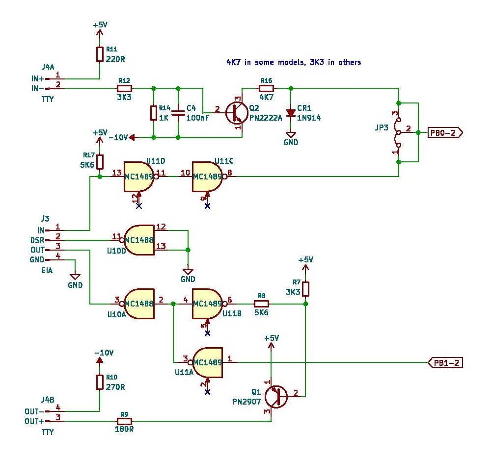
The serial interface uses two pins of Port B. PB0 is serial output, PB1 serial input. THe srial signals are handled via bitbanging and the baudrate is determined at startup.
The hardware part of the Jolt has two options, selectable with jumpers:

  1. 20 mA current loop.
    Build with transistors and the resistors 220/270 to create the current loop.
  2. RS232C serial interface
    Classical solution with the line drivers 1488/1489.

Note that when using a TTL USB requires to invert the signals. You can tap the output from pin U11D, for the input you need an inverter (a spare 7404 will do) to connect to PB1

Routines RDT and WRT are for receiving and sending characters via the serial interface PB0 and PB1, bit-banged.
RDT echoes every character received as it comes in, bit for bit.

Determine baud rate at startup

0157   701C CA                 DEX             ; X=FF
0158   701D 9A                 TXS             ; SP=FF
0160   701E             ;                      ; COMPUTE BIT-TIME CONSTANT, X=FF
0161   701E             ;
0162   701E A0 01              LDY #1          ; SET TO MEASURE 2 BITS
0163   7020 84 E3              STY CRDLY       ;INIT OR DELAY TIME PARAMETER
0164   7022 AD 02 6E    R0     LDA MPB         ; WAIT FOR START
0165   7025 4A                 LSR A
0166   7026 90 FA              BCC R0
0167   7028             ;
0168   7028 8E 04 6E    R2     STX MCLKIT      ; START CLOCK INITIALLY WITH FF
0169   702B AD 05 6E    R3     LDA MCLKIF
0170   702E 10 04              BPL R4
0171   7030 E6 EA              INC MAJORT      ; COUNT MAJOR T
0172   7032 D0 F4              BNE R2          ; GO RESTART CLOCK WITH X = FF
0173   7034             ;
0174   7034 98          R4     TYA
0175   7035 4D 02 6E           EOR MPB
0176   7038 29 01              AND #1
0177   703A F0 EF              BEQ R3          ; WAIT FOR Y BIT 0 AND SERIAL-IN NOT EQU
0178   703C 88                 DEY
0179   703D 10 EC              BPL R3          ; LOOP UNTIL START OF BIT 2
0180   703F             ;
0181   703F AD 04 6E           LDA MCLKRD
0182   7042 49 FF              EOR #$FF        ; COMPLEMENT RESIDUE
0183   7044 4A          R5     LSR A           ; HALF IT
0184   7045 46 EA              LSR MAJORT      ; HALF MAJOR
0185   7047 90 02              BCC R6
0186   7049 09 80              ORA #$80        ; PROPAGETE HC TO LC
0187   704B C8          R6     INY
0188   704C F0 F6              BEQ R5
0189   704E 85 EB              STA MINORT


What is happening here?
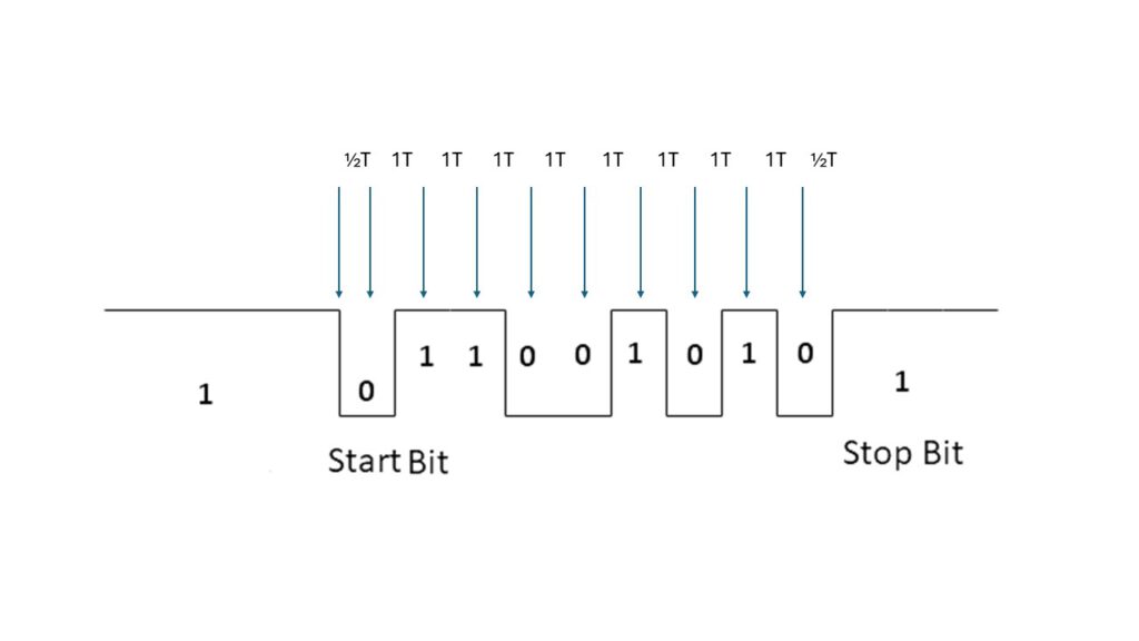
After RESET the baudrate is determined by measuring the length of the start bit of an incoming serial character. This means any character is usable where the first data bit is the opposite of the start bit (0). The TIM manual suggests using Carriage Return, which has the odd value 13, the lsb is 1 . SPACE ($20 0010 0000) for example does not work, any character with an odd value is OK.

The goal of this piece of code is to establish two variables: MAJORT and MINORT.

  • The routine is entered with X = FF due to the stack pointer initialization
  • The delay is measured by using the CLKIT Timer of the RRIOT filled with FF (174-179)
  • MINORT is the value to let the timer run
  • MAJORT is the number to repeat the timer
  • the exact timer value is corrected (181-189)

Delay half and whole bit time serial as determined at startup

0634   731D             ;
0635   731D 20 20 73    DLY2   JSR DLY1
0636   7320 48          DLY1   PHA               ; SAVE FLAGS AND A
0637   7321 08                 PHP
0638   7322 8A                 TXA               ; SAVE X
0639   7323 48                 PHA
0640   7324 A6 EA              LDX MAJORT
0641   7326 A5 EB              LDA MINORT
0642   7328             ;
0643   7328 8D 04 6E    DL2    STA MCLKIT
0644   732B             ;
0645   732B AD 05 6E    DL3    LDA MCLKIF
0646   732E 10 FB              BPL DL3
0647   7330 CA                 DEX
0648   7331 08                 PHP
0649   7332 AD 04 6E           LDA MCLKRD        ; RESET TIMER INT FLAG
0650   7335 28                 PLP
0651   7336 10 F3              BPL DL3
0652   7338             ;
0653   7338 68                 PLA               ; RESTORE REGS
0654   7339 AA                 TAX
0655   733A 28                 PLP
0656   733B 68                 PLA
0657   733C 60          DLX    RTS

What is happening here?

  • DLY2 waits one bit time (635).
  • DLY1 is used to wait one half bit time, as determined at startup.
  • Registers are saved (636-639)
  • The timer is run with value MINORT for MAJORT times (640-651)

WRT WROC Write character to serial interface

0572   72C6             ;
0573   72C6             ;  WRITE SERIAL OUTPUT
0574   72C6             ;  A = CHAR TO BE OUTPUT
0575   72C6             ;
0576   72C6 20 1D 73    WRT    JSR DLY2
0577   72C9 A2 09              LDX #9
0578   72CB             WROC   =WRT
0579   72CB 49 FF              EOR #$FF          ; COMPLEMENT A
0580   72CD 38                 SEC
0581   72CE             ;
0582   72CE 20 DA 72    WRT1   JSR OUT
0583   72D1 20 1D 73           JSR DLY2
0584   72D4 4A                 LSR A
0585   72D5 CA                 DEX
0586   72D6 D0 F6              BNE WRT1
0587   72D8 F0 3F              BEQ RDT5
0588   72DA                                      ; *USE BNE?
0589   72DA             ;
0590   72DA 48          OUT    PHA               ; SAVE A
0591   72DB AD 02 6E           LDA MPB           ; OUTPUT BIT FROM CY
0592   72DE 29 FD              AND #%11111101
0593   72E0 90 02              BCC OUT1
0594   72E2 09 02              ORA #%00000010
0595   72E4 8D 02 6E    OUT1   STA MPB
0596   72E7 68                 PLA               ; RESTORE A
0597   72E8 60                 RTS
0598   72E9             ;

What is happening here?

  • to be sure the serial line is quiet a bit time is waited (576)
  • send start bit via OUT(580)
  • send out 8 data bits and a stop bit (577)
  • complement character to write (579)
    • loop 9 bits
    • shift 8 databits into carry and send OUT with delay of one databit (582-586)
  • wait last bit as stop bit via carry, get out via RDT5 and OUT (585)

OUT

    isolate PB1 (592)
    if carry set bit else clear bit(592-594)
    set databit in PB1 (595)

RDT RDOC Read character from serial interface

0599   72E9             ;  OUTPUT  RETURNS CHAR IN A
0600   72E9             ;
0601   72E9 A5 E7       RDT    LDA HSPTR         ; TEST HS PTR OPTION
0602   72EB 4A                 LSR A
0603   72EC B0 4F              BCS RDHSR
0604   72EE             RDOC   =RDT
0605   72EE A2 08              LDX #8
0606   72F0             ;
0607   72F0 AD 02 6E    RDT1   LDA MPB
0608   72F3 4A                 LSR A             ; WAIT FOR START BIT
0609   72F4 90 FA              BCC RDT1
0610   72F6             ;
0611   72F6 20 20 73           JSR DLY1
0612   72F9 20 DA 72           JSR OUT           ; ECHO START BIT
0613   72FC             ;
0614   72FC 20 1D 73    RDT2   JSR DLY2
0615   72FF AD 02 6E           LDA MPB           ; CY = NEXT BIT
0616   7302 4A                 LSR A
0617   7303 20 DA 72           JSR OUT           ; ECHO
0618   7306             ;
0619   7306 08                 PHP               ; SAVE BIT
0620   7307 98                 TYA               ; Y CONTAINS CHAR BEING FORMED
0621   7308 4A                 LSR A
0622   7309 28                 PLP               ; RECALL BIT
0623   730A 90 02              BCC RDT4
0624   730C 09 80              ORA #$80          ; ADD IN NEXT BIT
0625   730E A8          RDT4   TAY
0626   730F CA                 DEX
0627   7310 D0 EA              BNE RDT2          ; LOOP FOR 8 BITS
0628   7312 49 FF              EOR #$FF          ; COMPLEMENT DATA
0629   7314 29 7F              AND #$7F          ; CLEAR PARITY
0630   7316             ;
0631   7316 20 1D 73           JSR DLY2
0632   7319 18          RDT5   CLC
0633   731A 20 DA 72           JSR OUT           ;AND DELAY 2 HALF-BIT-TIMES

What is happening here?
The read character routine echoes the incoming serial signal as it comes in!
Input is 8N1, reduced t0 7 databits

  • check if High Speed reader is wanted, branch to RDHSR (60-603)
  • 8 databits to receive (605)
  • Wait for startbit
  • delay half databit time
  • echo start bit to serial out
  • for 8 databits loop (605)
    • wait databit time 614)
    • read in databit into carry (615-616)
    • send out databit (617)
    • shift databit into received character (620-625)
  • complement received character (628)
  • mask off 8 bit parity (629)
  • wait databit time
  • send stop bit (632 – 633)
  • fall into DLY2 and return there (634-657

Data storage and defines

0084   0000             MDBK   =%00010110 ; X,X,X,PCR,DATA-AVAIL,GOT-DATA,SERIAL-OUT,IN

0 PB0 input serial IN
1 PB1 output serial OUT
1 PB2 is output GOT-DATA High speed reader
0 PB3 is input DAT-AVAIL High Speed reader
1 PB4 is output PCR , map TIM ROM in 
0 PB5 is input unused
0 PB6 is input unused
0 PB7 is input unused

0085   0000             DAVAIL =$08                ; PIN number mask High speed reader 
0086   0000             GOTDAT =$04                ; PIN number mask High speed reader 

 
0087   0000             IOBASE =$6E00             ; 6530-004 RRIOT addresses
0088   0000             MPA    =IOBASE+0          ; Port A data
0089   0000             MDA    =IOBASE+1          ; Port A Data direction
0090   0000             MPB    =IOBASE+2          ; Port B data
0091   0000             MDB    =IOBASE+3          ; Port B Data direction
0092   0000             MCLKIT =IOBASE+4          ; timer 
0093   0000             MCLKRD =IOBASE+4 
0094   0000             MCLKIF =IOBASE+5

0095   0000             UINT   =$FFF8             ; user vector

0096   0000             NCMDS  =7                 ; TOTAL NUMBER OF COMMANDS

0097   0000             MP0    =$7000
0098   0000             MP1    =$7100
0099   0000             MP2    =$7200
0100   0000             MP3    =$7300

0101   0000             ;
0102   0000             ;  ZERO PAGE MONITOR RESERVE AREA
0103   0000             ;
0104   0000             CRDLY  =227   $E3            ;DELAY FOR CR IN BIT-TIMES
0105   0000             WRAP   =228   $E4            ;ADDRESS WRAP-AROUND FLAG
0106   0000             DIFF   =229   $E5
0107   0000             HSPTR  =231   $E7
0108   0000             HSROP  =232   $E8
0109   0000             PREVC  =233   $E9
0110   0000             MAJORT =234   $EA
0111   0000             MINORT =235   $EB
0112   0000             ACMD   =236   $EC
0113   0000             TMP0   =238   $EE
0114   0000             TMP2   =240   $F0
0115   0000             TMP4   =242   $F2
0116   0000             TMP6   =244   $F4
0117   0000             PCL    =246   $F6
0118   0000             PCH    =247   $F7
0119   0000             FLGS   =248   $F8
0120   0000             ACC    =249   $F9
0121   0000             XR     =250   $FA
0122   0000             YR     =251   $FD
0123   0000             SP     =252   $FE
0124   0000             SAVX   =253   $FD
0125   0000             TMPC   =254   $FE
0126   0000             TMPC2  =255   $FF
0127   0000             RCNT   =TMPC  $FE
0128   0000             LCNT   =TMPC2 $FF

Run program and debugging

The GO command allows to run a program.
– Load a program via the LH load papertape command. End the load with typing ;00
– set breakpoints with the BRK ($00) instruction.
– Set the TIM to Registermode with R
– Set the current address with ‘:’ followed by the address in four hex bytes
– Type G

Inspect and alter registers with the M and R and : commands
Remove breakpoints by inserting the original instruction code

0065   0000          ;  SETTING AND RESETTING PROGRAM BREAKPOINTS
0066   0000          ;  -----------------------------------------
0067   0000          ;
0068   0000          ;      BREAKPOINTS ARE SET AND RESET USING THE MEMORY DISPLAY
0069   0000          ;          AND ALTER COMMANDS.  BRK HAS A '00' OPERATION CODE.
0070   0000          ;      TO SET A BREAKPOINT SIMPLY DISPLAY THE MEMORY LOCATION
0071   0000          ;          (FIRST INSTRUCTION BYTE) AT WHICH THE BREAKPOINT IS
0072   0000          ;          TO BE PLACED THEN ALTER THE LOCATION TO '00'.  THERE IS
0073   0000          ;          NO LIMIT TO THE NUMBER OF BREAKPOINTS THAT CAN BE
0074   0000          ;          ACTIVE AT ONE TIME.
0075   0000          ;      TO RESET A BREAKPOINT, RESTORE THE ALTERED MEMORY LOCATION
0076   0000          ;          TO ITS ORIGINAL VALUE.
0077   0000          ;      WHEN AND IF A BREAKPOINT IS ENCOUNTERED DURING EXECUTION,
0078   0000          ;          THE BREAKPOINT DATA PRECEDEC BY AN ':' IS DISPLAYED.
0079   0000          ;          THE PROGRAM COUNTER VALUE DISPLAYED IS THE BRK
0080   0000          ;          INSTRUCTION LOCATION + 1.

Example program

0001   0000             ;
0002   0000             ; TIM checkout program
0003   0000             ; TIM manual page 17
0004   0000             ;
0005   0000             ; .R  0117 3F 6C 0D FD FF
0006   0000             ; .:  0100
0007   0000             ; 
0008   0000             ; .R  0100 B0 10 0D 05 FF
                        ;.G
                        ; !"#$%&'()*+,-./0123456789:;<=>?@ABCDEFGHIJKLMNOPQRSTUVWXYZ[\]^_`abcdefghijklmno 
0009   0000             ; pqrstuvwxyz{|}
0010   0000             ; *  0116 3F 7E 0D FD FF
0011   0000             ; .
0012   0000             
0013   0000             
0014   0000             ;
0015   0000             CRLF    =   $728A     ; CRLF 
0016   0000             WRT =   $72C6         ; write a character to console
0017   0000             ; 
0018   0000             ; zeropage
0019   0000             CHAR    =   $00       ; storage for character
0020   0000             ;
0021   0100                     .ORG    $0100 ; start at $0100
0022   0100                     ;
0023   0100 20 8A 72    CHSET   JSR     CRLF
0024   0103 A9 20               LDA #$20      ; Start with space
0025   0105 85 00               STA CHAR      ;
0026   0107             ;
0027   0107 A5 00       LOOP    LDA     CHAR  ; get character
0028   0109 C9 7E               CMP #$7E    
0029   010B F0 08               BEQ     DONE
0030   010D 20 C6 72            JSR     WRT   ; print character
0031   0110 E6 00               INC CHAR
0032   0112 4C 07 01            JMP LOOP      ; next char
0033   0115             ;
0034   0115 00          DONE    BRK
0035   0116             ;
0036   0116                     .END
0037   0116                     
0038   0116                     
            		
tasm: Number of errors = 0
.LH
;160100208A72A9208500A500C97EF00820C672E6004C07010007F7
;00
.R  CE05 35 55 DB 00 DB
.:  0100
.R  0100 35 55 DB 00 DB
.G
 !"#$%&'()*+,-./0123456789:;<=>?@ABCDEFGHIJKLMNOPQRSTUVWXYZ[\]^_`abcdefghijklmno
pqrstuvwxyz{|}
 *  0116 33 7E 0D 05 FF
.