
A list of KIM-1 emulators/simulators
To be included in this list, the emulator should run the original KIM-1 ROM’s. I prefer to see source code, which all do except Kimplement. If I can not run it, it is not on this list (I know of an Apple iPhone and a Palm Pilot version) .
My favorites are of course my own KIM Simulator (for TTY programs) and the KIM-1 emulator in JavaScript (for LED display programs).
Troublemakers in KIM-1 emulation are due to the bit banging nature of the KIM-1 system:
- Serial I/O.
Since the KIM-1 uses bit banging to do serial I/O this is hard to emulate. Therefore most emulators patch the ROM at the GETCH and OUTCH locations to send and receive a character, including the hardware echo of GETCH - The automatic baudrate detection, also a bit banging routine, is patched out since it has no meaning with patched serial I/O routines and makes the emulator hang at boot.
- Break detection.
Most KIM-1 programs, like MS-Basic, break/stop detection by a BIT at location $1740. This of course does not work on patched serial I/O, so a patch at location 1740 is required. - The finer details of the serial interface, like PB0, PB5, PB7 and PB7 are often not implemented, so the hardware echo can not be prevented.
- Tape I/O, $1800, $1873, is often replaced by some form of dumping /loading memory with the start and stop and ID of the original routine with a binary file or omitted
- LED displays.
Also bit banging. By calling the SCANDS routine, repeated at a fast rate, the LED segments are switched on and off. The data, six nibbles interpreted as a hex number, per LED display comes from $F9, $FA, $FB, for a total of six digits. A bit complicated (see the information below) and hard to emulate without flickering.
A solution is to patch the SCANDS routine and displaying the hex without the switching off of segments. This works fine for the KIM-1 ROM itself and many programs that call SCANDS to light the LEDs. If the program (many First Book of KIM games e.g.) does bypass SCANDS and go directly to the hardware, it will fail.
Below is a list of, known to me, KIM-1 emulators/simulators. Details below the table.
| ——————— | ————- | ————- | —————— | ——– | |
| Name, website | Platform | Serial I/O | LED display | Tape | |
|---|---|---|---|---|---|
| ——————— | ————- | ————- | —————— | ——– | |
| KIM-1 Simulator | Windows, Linux, MacOS | terminal builtin | SCANDS emulation | None | |
| ——————— | ————- | ————- | —————— | ——– | |
| Linux terminal KIM-1 Emulator | Linux | CLI | CLI SCANDS emulation | Yes | |
| ——————— | ————- | ————- | —————— | ——– | |
| KIM-1 emulator in JavaScript | Web browser | No | Hardware emulation | None | |
| ——————— | ————- | ————- | —————— | ——– | |
| The Incredible KIMplement | C64 | Yes | Yes | ? | |
| ——————— | ————- | ————- | —————— | ——– | |
| KIM UNO | ARDUINO, ESP32, Windows, Linux | Yes | Yes | Yes | |
| ——————— | ————- | ————- | —————— | ——– | |
| VKIM | PALM OS (And HTML 5 browser, see VKIM | Yes | Yes | Yes | |
| ——————— | ————- | ————- | —————— | ——– |
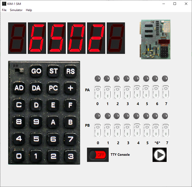
KIM-1 Simulator
My own attempt to KIM-1 emulation. The goal is more to test and study 6502 software for the KIM-1 than cycle exact LED display KIM-1 emulation.
A GUI application. The LED display is simulated by patched SCANDS, so hex digits only, no LED games.
Serial TTY is fully supported including echo suppress and Break detection via the built-in glass teletype console.
Debugging mode allows full access tot the innards of the 6502 or 65C02, the KIM-1. memory view, single/multiple step, run to breakpoint, instruction logging,, cycle counter, disassembly.
Loading and saving to many common formats like MOS papertape, Intel Hex, Motorola S record, binary, hex.
Both RRIOTs, a 6850 ACIA, a LE/switch to the free RRIOT port, RAM to E000, a utility ROM at F000. Runs all known TTY programs.
Things not working yet: LED displays via hardware RRIOT ports (without flickering!), timers in RRIOTs, timed execution to 1 MHz, tape emulation (including the Micro ADE tape motor control support).
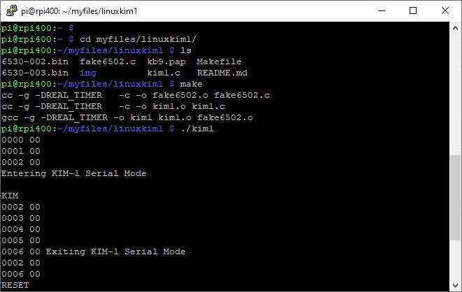
Linux KIM-1 emulator
A command line KIM-1 emulator, running on Linux. Runs fine on Raspberry Pi OS.
Simulates LED display with characters displayed at the terminal. Every key entered results in a new line with the LED display. Also supports TTY mode, be it limited to the maximum of 5K RAM in lower memory.
A good attempt to stay close to the bit banging nature of the keyboard entry routine. Limits speed to 1 MHz.
The Incredible KIMplement
A KIM-1 emulator running on a Commodore 64. Which means it will be slow, since 1 MHz 6510 running an emulated 6502, you get the picture. I did test run/Kimplement a long time ago in an C64 emuatator, The Incredible KIMplement is a KIM-1 emulator for the Commodore 64 (yes, this is not a joke — see the screenshot to the right). It is a true, partial emulation of the original KIM-1 hardware featuring:
- Powered by “6o6” — a full software NMOS 6502 emulation (documented opcodes only, sorry) with all addressing modes, simulated ROM, and simulated memory-mapped I/O
- LED and keypad emulation via partial RIOT emulation
- TTY emulation (ASR-33 subset) via partial RIOT emulation
- SST emulation
- 4K RAM expander card
- KIM-4 emulation with 8K RAM expander card (thus total address space 16K)
- Revision E ROMs built-in, so you don’t have to find a pirated set download them from your own KIM
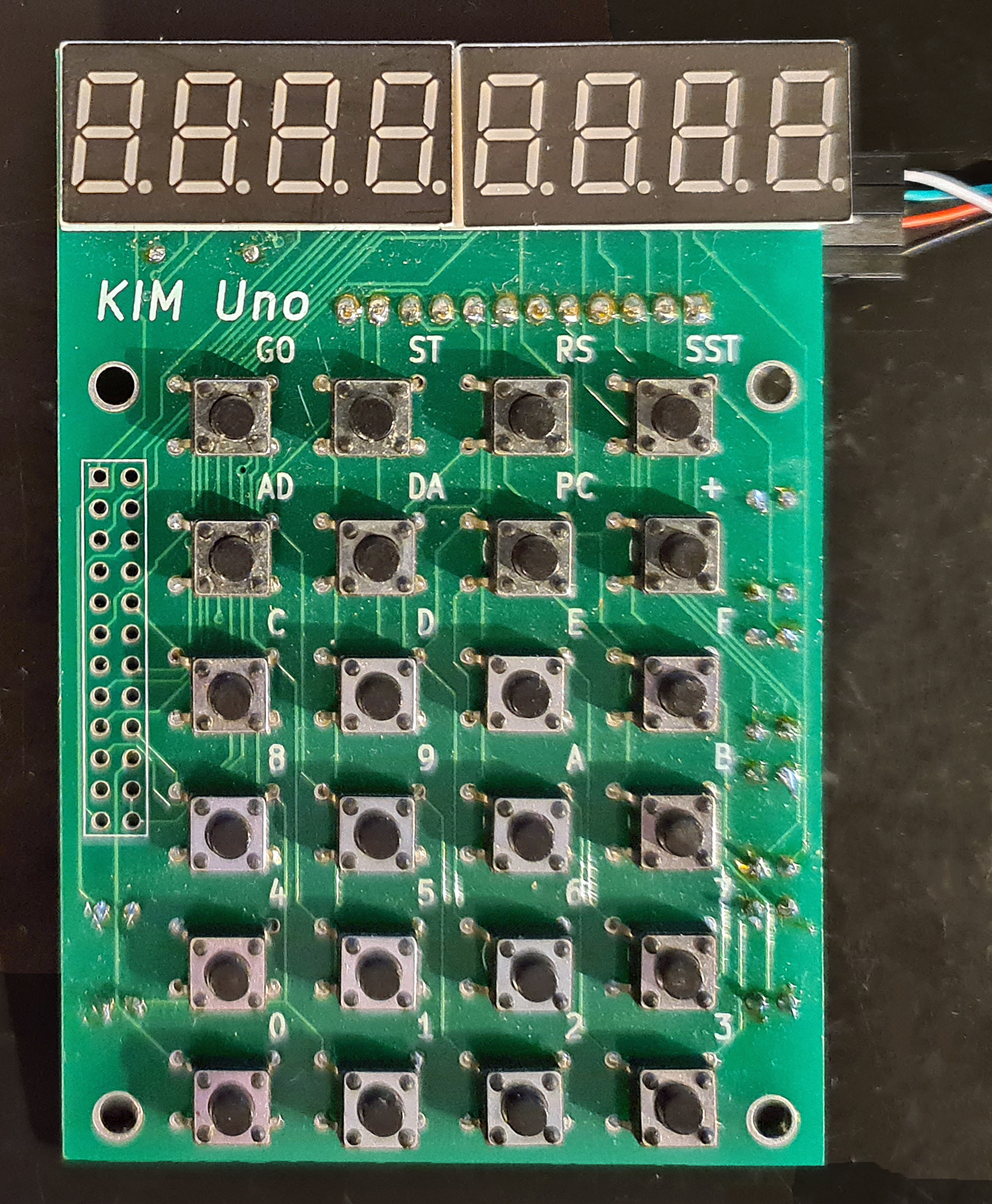
KIM UNO
The KIM Uno, designed and produced and sold by Oscar Vermeulen, is a very simple “open-source hardware” project that started out as a replica of the classic 1976 KIM-1 computer. Later, Apple-1 compatibility and a 6502 programmable calculator mode were added, plus a built-in ‘early 6502 software gems’ collection.
It costs about $10 in commonly available parts (board & parts without case or power supply), but provides a faithful KIM-1 ‘experience’. An Arduino Pro Mini mounted on the back contains all the logic and memory.
I have two versions: the ‘original’ and the later redesigned version, Software-wise the same, with on the top of the PCB room for power connector (GND, +5V or a 9V battery) and a slide switch. , I use them with an USB cable (the blue one of this page) for power and the serial interface provided.
The software already works on the blue pill STM32 or an ESP32, with manual cabling to the keyboard/display and I expect a new version of the PCB for the ESP32.
The software for the serial interface (you really need a good serial terminal emulator, like Minicom or Tera Term) can be used on any Arduino Uno. After power on it delivers a simulation of the LED display or the real KIM TTY teletype interface (a bit broken in the current version).
All well described on the pages of Oscar and well worth the money for a ‘6502 SBC’ experience or a Cosmac 1802 with a small LCD.
KIM-1 emulator in JavaScript
By Code Monkey King, web browser based, run it here.
Emulates the keypad/LED display part only. Hardware emulation of LED display. Emulates KIM-1 LED display very well!
Some handy tools like 6502 assembler, paper tape format converter and hexdump generator
No TTY, limited RAM.
Code on github

KIM-1 hardware information relevant to emulation
RAM ROM I/O

OVERVIEW OF KIM-1 MEMORY MAP fully extended (A-K connected!)

 0000-1400 RAM
 1600-1700 free, can be RAM or I/O or ROM
 1700-173F I/O and timer of 6530-003
   1700 Port A,
   1701 DDR Port A
   1702 Port B,
   1703 DDR Port B
   1704- timer
 1740-177F I/O and timer of 6530-002, used by  LED/Keyboard/tape
   1740 Port A,
   1741 DDR Port A
   1742 Port B,
   1743 DDR Port B
   1744- timer
 1780-17BF RAM from 6530-003  , free for user applications
 17C0-17FF RAM from 6530-002  , free for user except 0x17E7-0x17FF
 1800-1BFF ROM003
 1C00-1FFF ROM002
    emulator  mirrors last 6 bytes of ROM 002 to FFFB-FFFF:
 2000 - DFFF RAM in simulator

 F000-       ROM in simulator for patching KIM-1 ROM serial I/O and keypad
 FFFA, FFFB - NMI Vector  copy of KIM-1 ROM ROM002
 FFFC, FFFD - RST Vector  copy of KIM-1 ROM ROM002
 FFFE, FFFF - IRQ Vector  copy of KIM-1 ROM ROM002


| ADDRESS |      AREA      | LABEL |              FUNCTION               |
|         |                |       |                                     |
|  00EF   |                | PCL   | Program Counter - Low Order Byte    |
|  00F0   |                | PGH   | Program Counter - High Order Byte   |
|  00F1   |     Machine    | P     | Status Register                     |
|  00F2   |     Register   | SF    | Stack Pointer                       |
|         |     Storage    |       |                                     |
|  00F3   |     Buffer     | A     | Accumulator                         |
|  00F4   |                | Y     | Y-Index Register                    |
|  00F5   |                | X     | X-Index Register                    |
|  1700   |                | PAD   | 6530-003 A Data Register            |
|  1701   |   Application  | PADD  | 6530-003 A Data Direction Register  |
|  1702   |        I/O     | PBD   | 6530-003 B Data Register            |
|  1703   |                | PBDD  | 6530-003 B Data Direction Register  |
|  1704   |                |       | 6530-003 Interval Timer             |
|         | Interval Timer |       |   (See Section 1.6 of               |
|         |                |       |    Hardware Manual)                 |
|  170F   |                |       |                                     |
|  17F5   |                | SAL   | Starting Address - Low Order Byte   |
|  17F6   |   Audio Tape   | SAH   | Starting Address - High Order Byte  |
|  17F7   |   Load & Dump  | EAL   | Ending Address - Low Order Byte     |
|  17F8   |                | EAH   | Ending Address - High Order Byte    |
|  17F9   |                | ID    | File Identification Number          |
|  l7FA   |                | NMIL  | NMI Vector - Low Order Byte         |
|  l7FB   |                | NMIH  | NMI Vector - High Order Byte        |
|  l7FC   |   Interrupt    | RSTL  | RST Vector - Low Order Byte         |
|         |    Vectors     |       |                                     |
|  17FD   |                | RSTH  | RST Vector - High Order Byte        |
|  l7FE   |                | IRQL  | IRQ Vector - Low Order Byte         |
|  17FF   |                | IRQH  | IRQ Vector - High Order Byte        |
|  1800   |                | DUMPT | Start Address - Audio Tape Dump     |
|         |  Audio Tape    |       |                                     |
|  1873   |                | LOADT | Start Address - Audio Tape Load     |
|  1C00   | STOP Key + SST |       | Start Address for NMI using KIM     |
|         |                |       | "Save Nachine" Routine (Load in     |
|         |                |       | 17FA & 17FB)                        |
|  17F7   |   Paper Tape   | EAL   | Ending Address - Low Order Byte     |
|  17F8   |    Dump (Q)    | EAH   | Ending Address - High Order Byte    |


KIM-1 hardware


PA SAD, SADD
PB SBD  SBDD

PB0 TTY data out (can block  hardware TTY echo)
PB1 - PB4 outputs led select via 74145 6 leds O4 -O9 on/off, keypad O0-O3
PB5 TTY/audio control (block/allow inputs)
    can block TTY input and audio input
PB7 audio in/out


PA0-6 keypad + LED segments
PA7 TTY data in

74145

PB1 - PB4 to ABCD inputs
Outputs
O4 to O9 LED on U18 to U23

O0 to O3 to key rows


PB   PB1 PB2 PB3 PB4
     A   B   C   D
00-01   0   0   0   0  00 O0 keyrow 0
02-03   1   0   0   0  01 O1        1
04-05   0   1   0   0  02 O2        2
06-07   1   1   0   0  03 O3        3

08-09   0   0   1   0  O4 LED enable U18
0A-0B   1   0   1   0  O5            U19
0C-0D   0   1   1   0  O6            U20
0E-OF   1   1   1   0  O7            U21
10-11   0   0   0   1  O8            U22
12-13   1   0   0   1  o9            U23


Inits
 750  1E8C  A2 00     INIT1   LDX   #$00
 751  1E8E  8E 41 17          STX   PADD      FOR SIGMA USE SADD
PAx is input


 752  1E91  A2 3F             LDX   #$3F
 753  1E93  8E 43 17          STX   PBDD      FOR SIGMA USE SBDD
3F = 00111111
PB0 - PB5 output, PB7 input


 754  1E96  A2 07             LDX   #$07      ENABLE DATA IN
 755  1E98  8E 42 17          STX   SBD       OUTPUT
PB0 = 1 high TTY, stopbit
PB1 -PB2 high (keypad?)

PB5 low ; allow input
PB7 low : audio quiet

Print OUTSP

toggle PB0 via read SBD, AND $FE, OR $01 and write SBD, end with 1


** SUB TO DETERMINE IF KEY IS DEPRESSED OR

              ;          CONDITION OF SSW KEY NOT DEPRESSED OR
 805                  ;          TTY MODE  A=0
 806                  ;          KEY DEPRESSED OR KB MODE  A NOT ZERO
 807  1EFE  A0 03     AK      LDY   #$03      3 ROWS
 808  1F00  A2 01             LDX   #$01      DIGIT 0
 809  1F02  A9 FF     ONEKEY  LDA   #$FF
 810  1F04  8E 42 17  AK1     STX   SBD       OUTPUT DIGIT
via 74145 Start with digit 0, continue with next row


 811  1F07  E8                INX             GET NEXT DIGIT
 812  1F08  E8                INX
 813  1F09  2D 40 17          AND   SAD       INPUT SEGMENTS
and key pressed to A

 814  1F0C  88                DEY
 815  1F0D  D0 F5             BNE   AK1

 816  1F0F  A0 07             LDY   #$07
 817  1F11  8C 42 17          STY   SBD
back to INITS state

 818  1F14  09 80             ORA   #$80
 819  1F16  49 FF             EOR   #$FF
set high bit and inverse all
A=0 no key

 820  1F18  60                RTS


 822  1F19  A0 00     SCAND   LDY   #$00      GET DATA                      1F19
 823  1F1B  B1 FA             LDA   (POINTL),Y  SPECIFIED BY POINT
 824  1F1D  85 F9             STA   INH       SET UP DISPLAY BUFFER

 825  1F1F  A9 7F             LDA   #$7F      CHANGE SEG
 826  1F21  8D 41 17          STA   PADD      TO OUTPUT

PA0 - PA6 output

 827  1F24  A2 09             LDX   #$09      INIT DIGIT NUMBER start with U18
 828  1F26  A0 03             LDY   #$03      OUTPUT 3 BYTES 6 hex numbers
 829  1F28  B9 F8 00  SCAND1  LDA   INL,Y     GET BYTE
 830  1F2B  4A                LSR   A         GET MSD high byte
 831  1F2C  4A                LSR   A
 832  1F2D  4A                LSR   A
 833  1F2E  4A                LSR   A
 834  1F2F  20 48 1F          JSR   CONVD     OUTPUT CHAR
 835  1F32  B9 F8 00          LDA   INL,Y     GET BYTE AGAIN
 836  1F35  29 0F             AND   #$0F      GET LSD low byte
 837  1F37  20 48 1F          JSR   CONVD     OUTPUT CHAR
 838  1F3A  88                DEY             SET UP FOR NEXT BYTE
 839  1F3B  D0 EB             BNE   SCAND1
 840  1F3D  8E 42 17          STX   SBD       ALL DIGITS OFF
X = 0?


 841  1F40  A9 00             LDA   #$00      CHANGE SEGMENT
 842  1F42  8D 41 17          STA   PADD      TO INPUTS
PA0-PA7 inputs


 843  1F45  4C FE 1E          JMP   AK        GET ANY KEY

 844                  ;       ** CONVERT AND DISPLAY HEX (USED BY SCAND ONLY)**
show character on LED


 845  1F48  84 FC     CONVD   STY   TEMP
 846  1F4A  A8                TAY             SAVE Y
 847  1F4B  B9 E7 1F          LDA   TABLE,Y   USE CHAR AS INDEX
 848  1F4E  A0 00             LDY   #$00      LOOKUP CONVERSION
 849  1F50  8C 40 17          STY   SAD       TURN OFF SEGMENTS
PA0-PA7 0

 850  1F53  8E 42 17          STX   SBD       OUTPUT DIGIT ENABLE
X = LED number U18-U23 decimal  to 74145

 851  1F56  8D 40 17          STA   SAD       OUTPUT SEGMENTS
write segment from table to LED

 852  1F59  A0 7F             LDY   #$7F      DELAY 500 CYCLES
 853  1F5B  88        CONVD1  DEY
 854  1F5C  D0 FD             BNE   CONVD1
 855  1F5E  E8                INX             GET NEXT DIGIT NUMBER
 856  1F5F  E8                INX             ADD 2
 857  1F60  A4 FC             LDY   TEMP      RESTORE Y
 858  1F62  60                RTS


GETKEY > 15 ? no key
14 = PC
10 = addressmode
11 - Datamode
12 = step
13 = RUN
0 - F - hex digit

/* RIOT2 explanation: better emulation of LED display through simulated hardware rather than 2014's ROM patch
 *
 *  The RIOT-002 chip is used to drive the LEDs, read the keypad, and control TTY and tape.
 *  KIM Uno only emulates the LED driver and timer hardware; the keypad, TTY and tape are emulated on a higher abstraction level in the ROM
 *
 *  On the real KIM-1, the keyboard columns are PA0-PA6 and the rows are selected through
 *                     the display  columns are PA0-PA6 and the segment led is decoded from PB 0000 1110
 *                     teletype mode is detected when  = 1.
 *                     teletype uses PB0, PB5, PA7
 *
 *  1740 Data port A            Selects pattern to show on a segment LED (PA0-6) and TTY (PA7)
 *  1741 Data Direction port A  Are the GPIO pins set to input or output?
 *  1742 Data port B            Selects which of the 6 segment LEDs is lit up (PB1-3),
 *                              and also: PB0 (TTY), PB4 ???, PB5 (TTY/tape input?), PB 6(RIOT internal, ChipSelect), PB7 (tape output)
 *  1743 Data direction port B  Are the GPIO pins set to input or output?
 */

void write1740(void)            // ======== PA pins - set the individual LED segments on or off
{
  //riot2regs.ioPAD &= 0x7F;    // only the bits for the 7 LEDs in a segment LED

  for (uint8_t ibit=0; ibit<7; ibit++)
      digitalWrite(kCols[ibit], (riot2regs.ioPAD & (1<<ibit))==0);       // set the bit, inverted through ==0
}

void write1741(void)            // ======== Data direction register for PA
{
  for (uint8_t ibit=0; ibit<7; ibit++)
    if ( riot2regs.ioPADD & (1<<ibit) )
      pinMode(kCols[ibit], OUTPUT);           // set pin to output
    else
      pinMode(kCols[ibit], INPUT);           // set pin to output
}

void write1742(void)            // ======== PB pins - set which of the 6 segment LEDs is lit up
{
  uint8_t led = ((riot2regs.ioPBD - 9) >> 1) & 0b111; // identify the selected segment LED

  for (uint8_t iLed=0;iLed<6;iLed++)       // set GPIO pins of all 6 KIM-1 LED segments
  { if (iLed==led)
      digitalWrite(ledSelect[iLed], HIGH); // power up this segment LED
    else
      digitalWrite(ledSelect[iLed], LOW);  // power down the other segment LEDs
  }
}

void write1743(void)            // ======== Data direction register for PB
{
  // TEMP: all LED pins are set to output; there's no functionality we need except that.
  for (uint8_t iLed=0;iLed<6;iLed++)
    pinMode(ledSelect[iLed], OUTPUT);
}
} // end of C segment