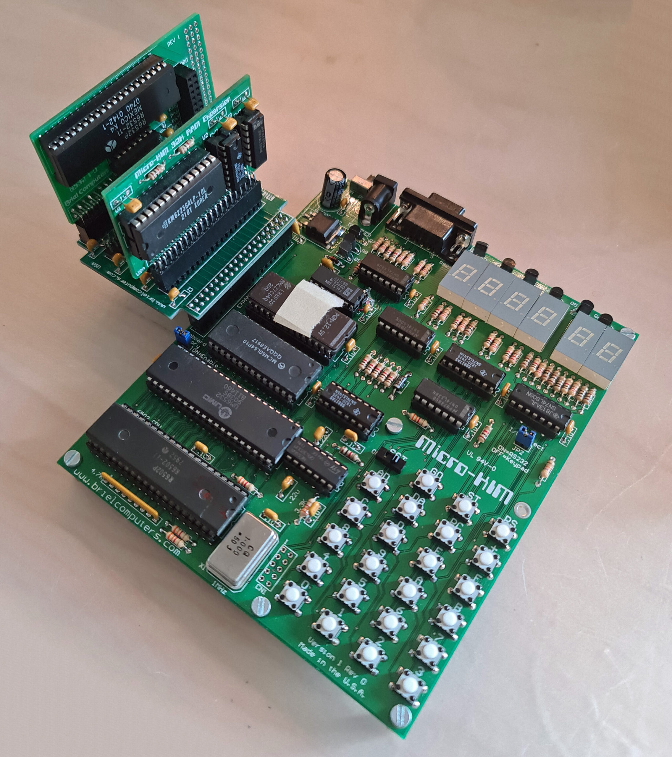
Optional add-ons to make the Micro-KIM a real KIM-1, with the second 6530/32 and a 32K RAM card to give enough RAM to run real programs like KB9 Basic.
The expansion connector is made for this. With the expansion board up to four cards can be added.
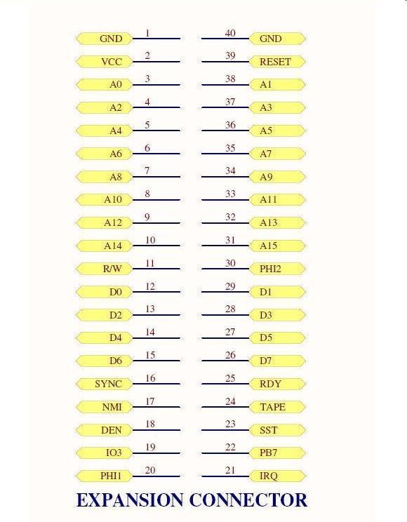
A 40 pins male connector. Pin 1 is labeled on the board and is near the edge at the upper-left corner
of the connector.
Here he description of the expansion connector. Also see the Circuit diagram.
| 1 and 40 | two pins for ground to give proper grounding to optional expansion boards. |
| 2 | VCC, this is a 5V signal which powers the circuit |
| 3-14, 31-38 | CPU address lines A0-A15 used to address memory or devices |
| 11 | R/W read/write signal. Low when writing, high when reading memory |
| 12-15, 26-29 | CPU data bus. Used to transfer data to/from RAM/EPROM or devices |
| 16 | Sync. This signal goes high during when an instruction is being fetched for the CPU |
| 17 | NMI. Non-Maskable Interrupt signal to the CPU. Active low to generate |
| 18 | DEN, Onboard memory decode Enable line. Control the enabling of the onboard memory |
| 19 | IO3 is the pre-decoded signal for the 2nd optional 6532. Attach to CS1 pin 38 on 6532 |
| 20 | PHI1 Phase 1 clock signal. 180 degrees from phase 2 |
| 21 | IRQ Interrupt request signal. Active low generates an IRQ. |
| 22 | PB7 is I/O port pin PB7 from 6532 required to complete cassette interface |
| 23 | SST Single step signal used to control CPU with single step |
| 24 | TAPE this signal is used to complete the cassette interface. |
| 25 | RDY used to stop the CPU in single step circuit |
| 30 | PHI2 phase 2 main clock signal to the 6502 |
| 39 | RESET 6502 RESET line, when pulled low will reset the 6502 |
32K RAM

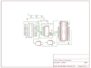 |
Circuit diagram of memory expansion |
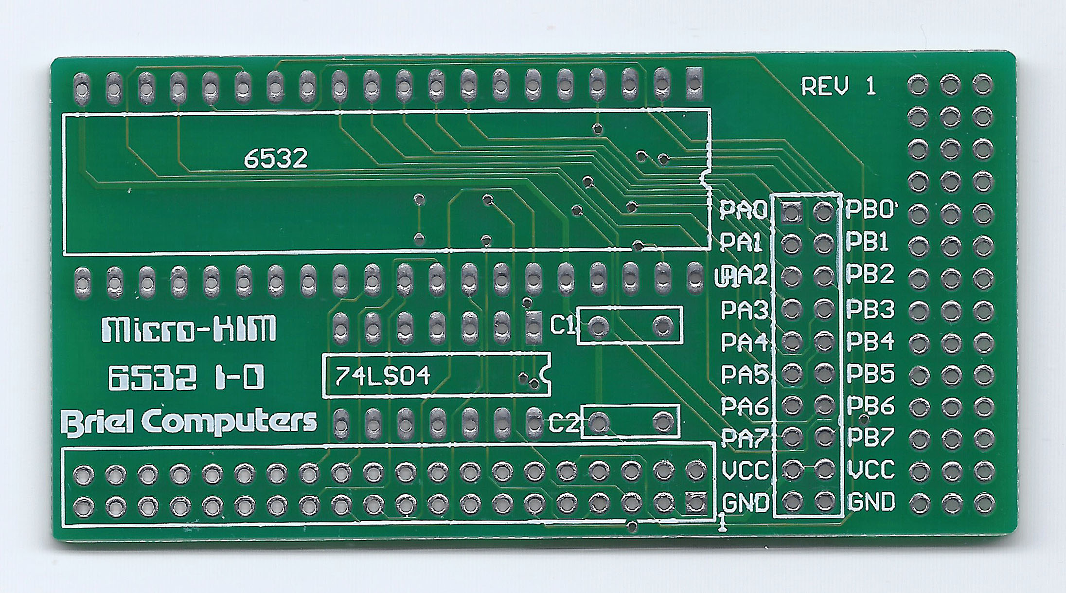
Second EPROM
The Micro-KIM is already prepared for a second 6532. The ROM for it is in place, the address decoding is also available. This card brings the second 6532 with the free I/O and timers to connector.

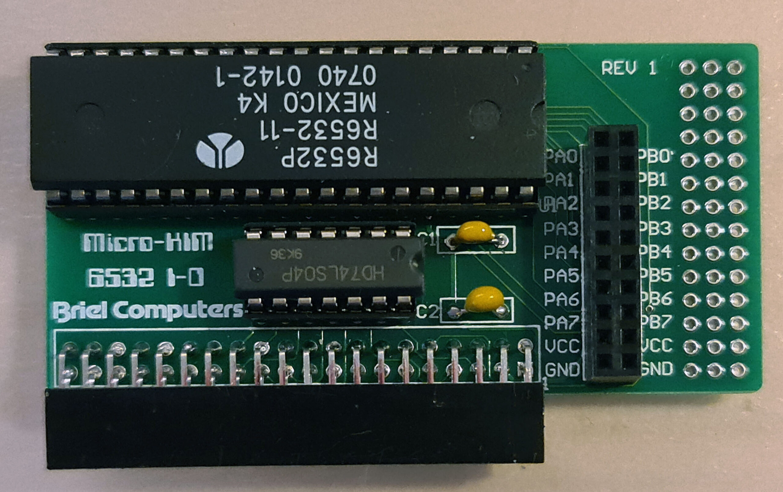
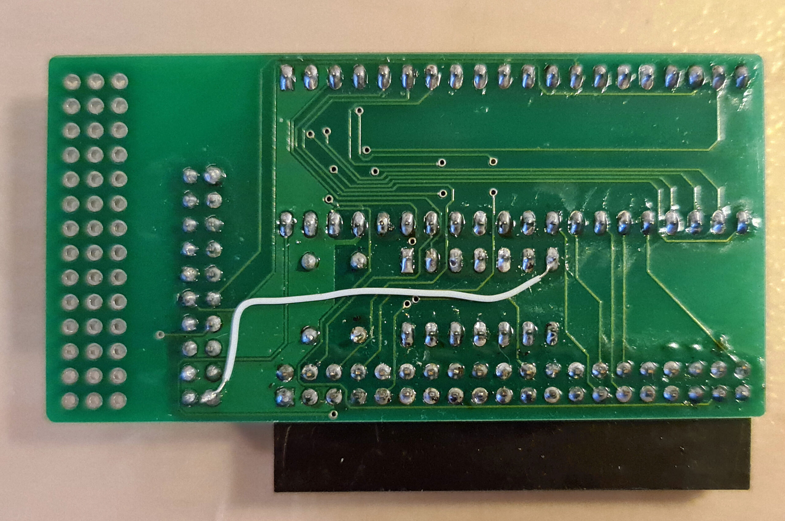
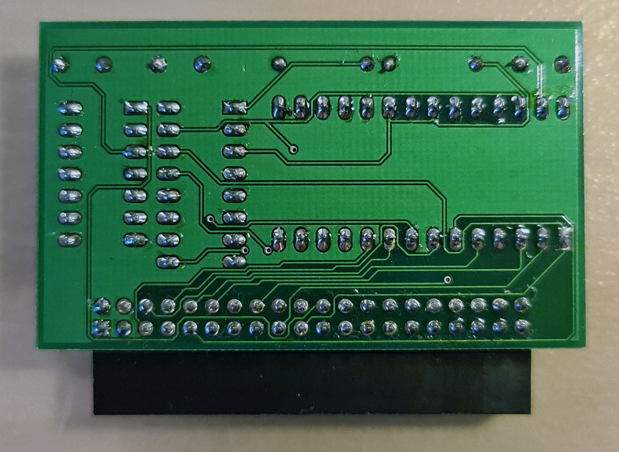
The revision I have needs a wire to connect the missing ground line to the 74LS04 (tip from azog, Silent Q).
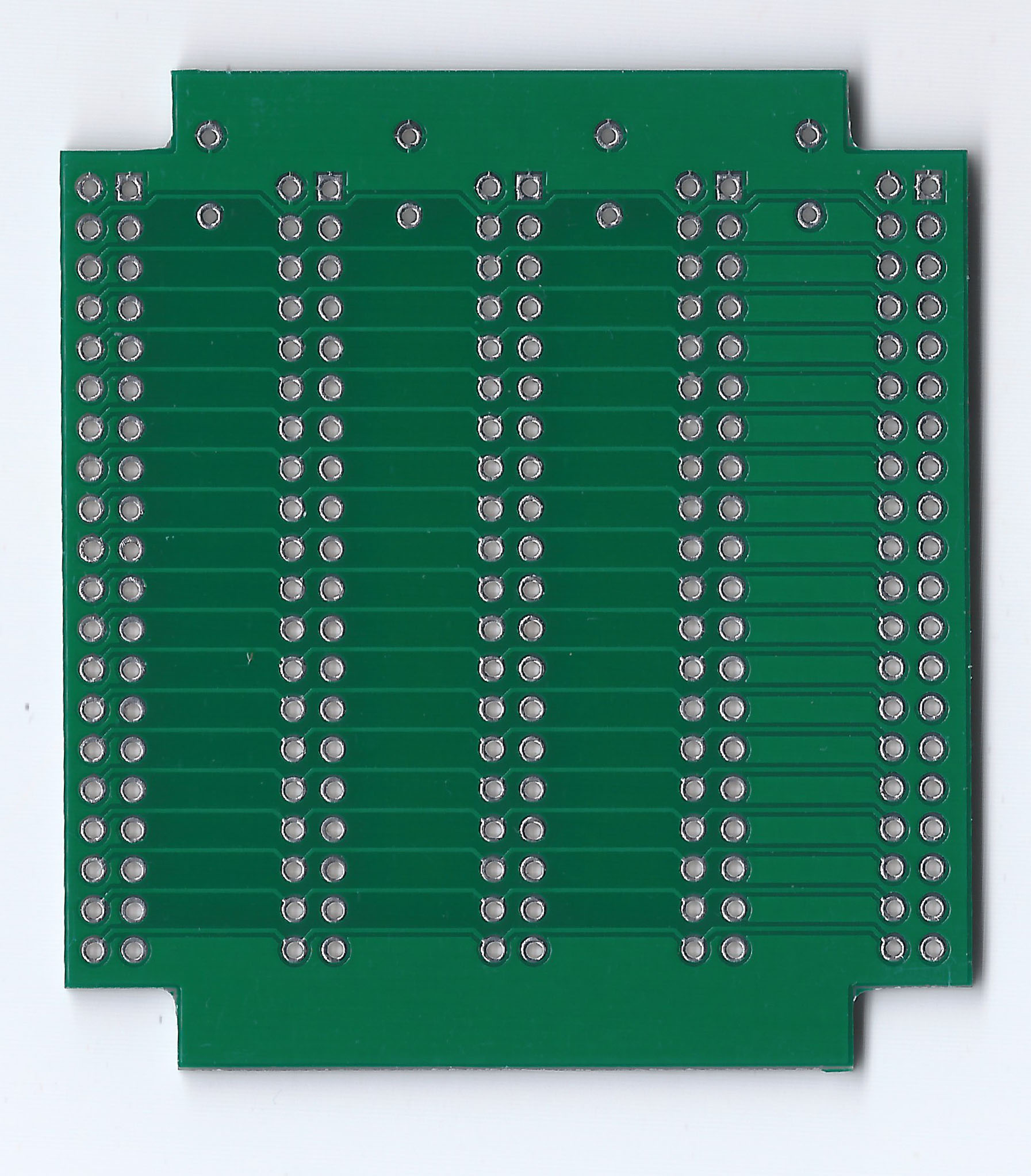
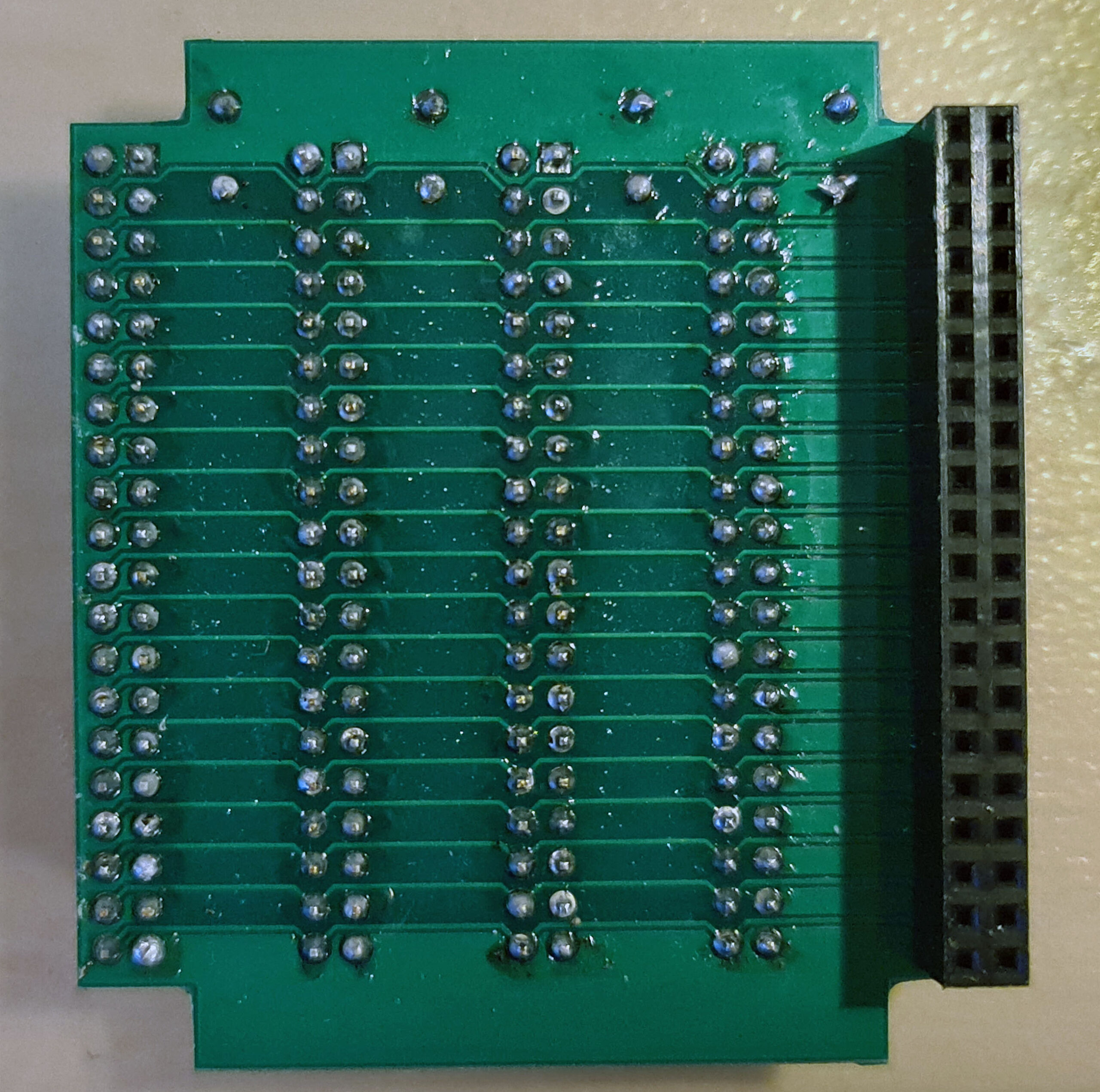
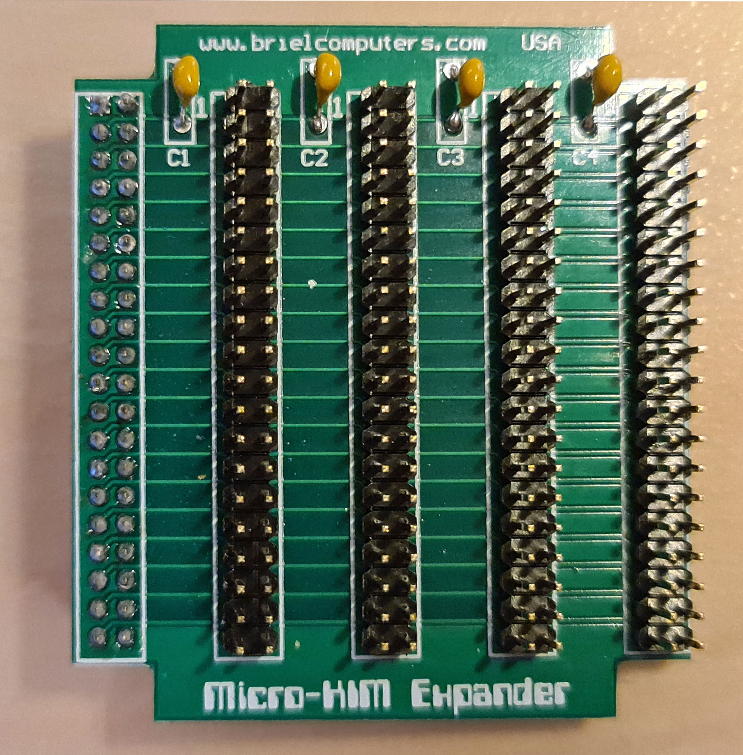
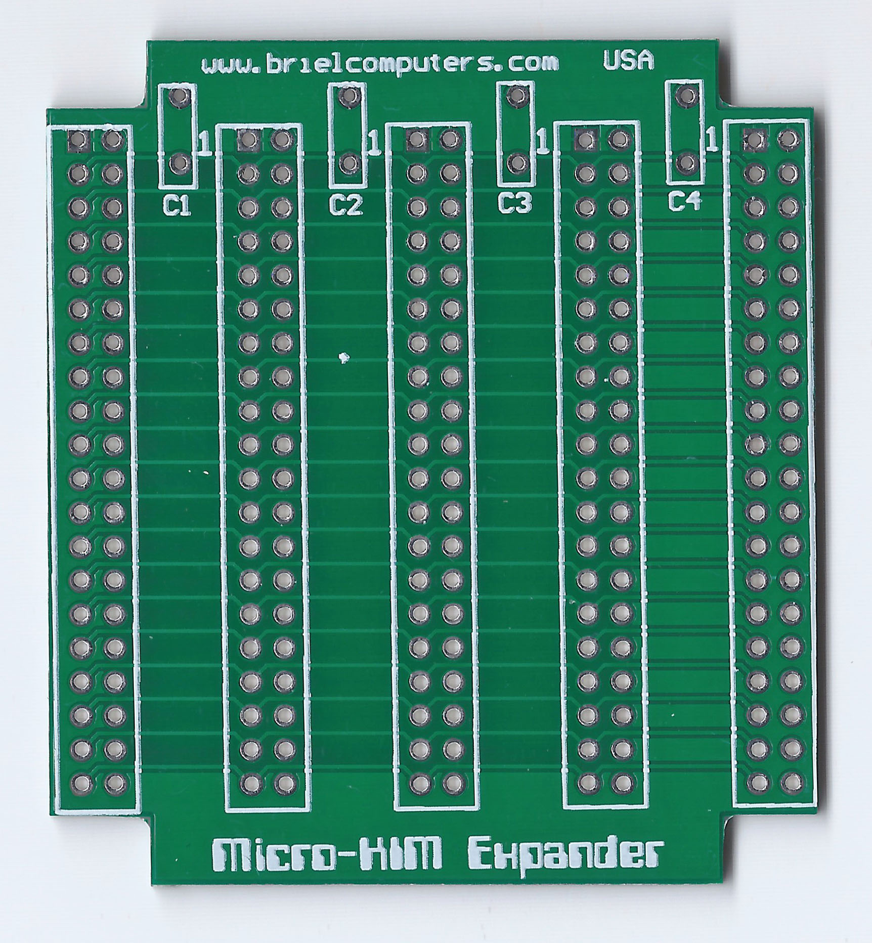
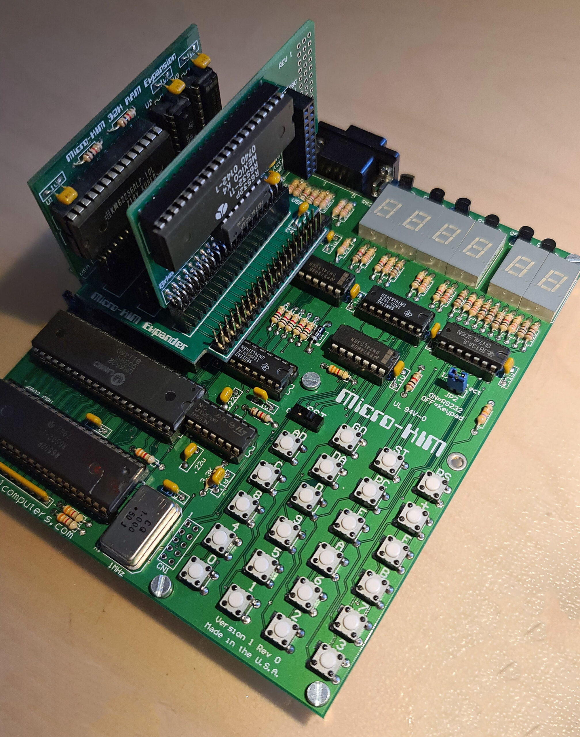
Expansion motherboard
With two expansion boards, both quite essential as shown above and one expansion connector, is not enough.
So the expansion board brings the expansion connector to four connectors, just one on one connected.
As you can see on the Cassette interface for the Micro-KIM page this makes for interesting additions.
The expansion board can be placed in two ways. The first way iverhanging the Micro-KIM for a compact solution. Or hanging outside, which makes attaching wires to expansion boards less risky. Always take care of the right orientation of the expansion boards, notice the ‘1’ on the baords and the exapnsion connector on the Micro-KIM.