
Original Uwe Schroeder, KIM Kenner 1, March 12 1977 Translation June 2021 Hans Otten
Introduction
A large number of KIM-1 users seem, like me, to have problems recording computer programs on the cassette recorder. For unknown reasons the KIM-1 refuses to read a program, while before it went well with the same tape. These problems have led me to study the KIM-1 system and I hope to have finally discovered the cause of the problem.
This article serves to aid other KIM-1 users to solve also these problems.
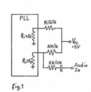
Part of the PLL circuit, including input impedances
Analysis of the KIM-1 FSK system
Signals are stored on the cassette tape with FSK (frequency Shift Keying). By consecutive high and low frequency sounds (on the KIM-1 3.6 kHz and 2.4 kHz). These high and low frequency sounds are generating not with much hardware, but with software. Reading programs is done by analyzing these sounds with the LM565 IC (a Phase Locked Loop, see User manual page 31 and fig 3.8). The fact if the sound was high or low frequency is determined after some amplification and filtering via a LM311 comparator to ‘0’ and ‘1’ and offered to I/O port PB7 of the second 6530 RRIOT).
The problems arising at the reading are probably caused by not correct functioning of the circuit around the PLL. The average cassette recorder appears to supply sometimes during a very short period a dropout to let the PLL function correctly.
Where and how things can go wrong with the PLL
- When we record on the cassette recorder a constant tone of 3.6 kHz and listen to the recording and examine it with an oscilloscope, we see and hear the sound volume fluctuate or even disappear for short periods, we call this dropouts of the tape. These dropouts will mean a fluctuation of the sound available for the PLL to detect 10 to 100 times lower volume and cause the detection to fail. By measuring the PLL level I have seen 10 to 100% more signal than required, so that ca mean PLL malfunction.
- If a tape is passing the head misaligned/tilted of the tape recorder head, higher frequencies are in the disadvantage and weaker. This head misalignment will cause problems with recordings from other tape recorders, bought or from other users.
- Suppose we use a perfect +5V power supply, then VCC can be considered ‘Ground’ When we send on Audio In a AC current of 550 mV, then resistors R8 andR14 reduce the signal 1/11 of 550 Mv = 50 mV supplied to the PLL. Measurements indicate the PLL requires at least 40mV to sync the PLL and see it as a ‘high’ frequency sound.
Remark: replace the R8 with 1K to give the PLL 250 mV instead of 50mV. - Suppose we use a perfect recorder with a very low output impedance. And suppose the power supply has a noise level of 600 mV. Fig 2 shows, after some calculations the noise level results in 40 mV on the PLL input. If we reduce the resistor to 1K , the noise level becomes 230 mV.
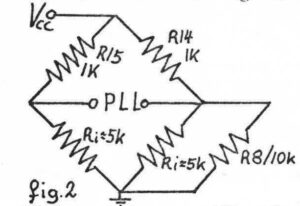 The specifications of the PLL indicate the correct functioning of the PLL at an input level of nominal 2, maximal 20 mV. The fact that the measurements indicate the PLL only operates at levels of 40 mV indicate the noise levels are at the same level as the input signal coning from the recorder. A better noise reduced may help, but other sources of interference are possible. Therefore extra amplification of the signal is preferred instead of altering the KIM-1 hardware.
Solve the tape recorder problems
Since the problems with reading of tapes on the KIM-1 seems to be related to fluctuating signal levels:
- Record the signal as loudly as possible, use a recorder without automatic level adjustment and record so that the tape is saturated.
- When using the loudspeaker output, experiment with the volume. But too loud means distortion and may also lead to failures.
- Build an amplifier for frequencies 2-4 kHz 10 to 20 times, short dropouts should be well amplified.
- Use C60 instead of C120 types. Normal cheap ferro is fine, Chrome has more dropouts.
- If the KIM-1 reports a reading error (FFFF in the display) and you want to know how much of the tape has been read, location 17ED and 17EE contain the first address not read yet.
Make a copy of finished programs on another cassette and check this copy for readability. Do not use this copy anymore and store it. When using a cassette often, this may lead to problems, like the mangling of the tape in the drive.
Troubleshooting
Here is a procedure to work around reading tape problems:
- Check if the recorder is connected to the KIM-1
- Check Volume and Tone control ((max high)
- Press Reset.
- Set location 17F9 to 0.
- Set location 00F1 to 0.
- Inspect location 1742. Here the information of I/O pin is shown. The display shows 1742 87
- Start the recorder. The middle bar of the 8 now will blink, if not : you have Error 6A (see below).
Stop the recorder, remove the cassette and start the recorder. Now the middle bar of the 8 should not blink, else you have Error 6B (see below) - If the Volume knob of your recorder controls the strength of the output signal: start the recorder and determine in which setting the blinking of the bar changes. If you have not enough headroom, see Error 7.
- Check of the correct detection of the high frequency.
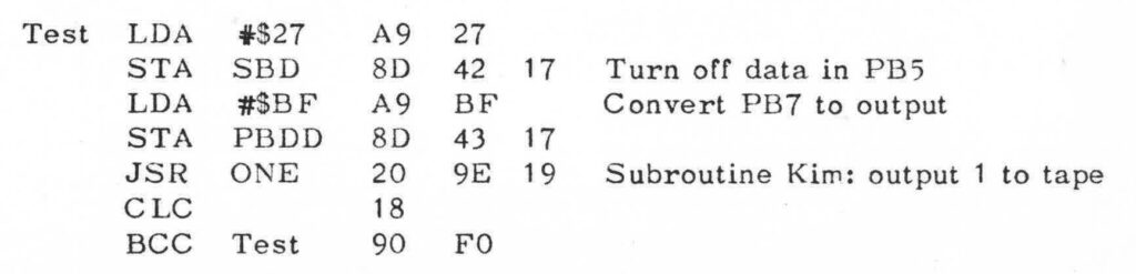
Type in the next program and start it (the program writes a constant tone of 3.6kHz to the recorder)
Record this tone on the recorder for several minutes.
Rewind the recorder and start playing. Now the display should show no middle bar 1742 07
The bar should not blink at all, every blink indicates a dropout or such. See Error 7 and Error 8. - Read User Manual C and E
Oscilloscope test
If you have an oscilloscope, do the following measurements.
- Attach the scope to Audio Out, e.g the negative side of C4 (user manual page B-1).
- If you have dual channel scope, connect the other input to the top of resistor R8, that is the PLL input.
- Set the timebase to 1 ms, and connect Audio-Out-High with Audio-In.
- Start a dump of memory with 1800G
The scope will now show figure 3.
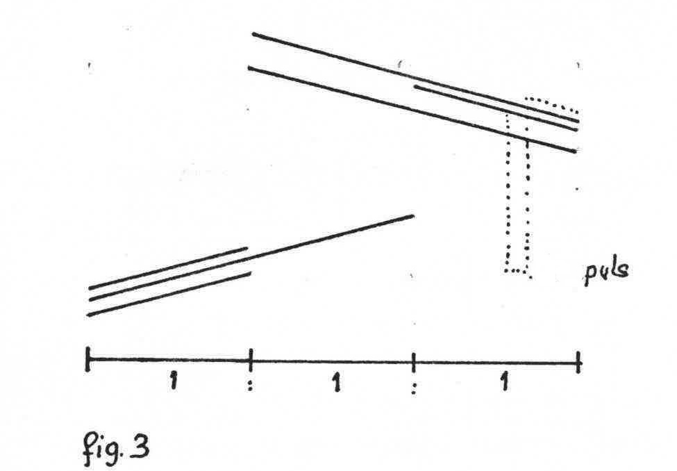
Stop the dump program , remove the connection between Audio-In and Audio Out-High and connect the cassette recorder to the KIM-1. Start reading the tape (1873G) and move the tape to a problem area. You need to start the reading program to avoid the interference of the display. When all is right you should see the same nice picture on the scope as before.
Now increase and lower the signal level of the cassette recorder to see, if or when, there are problems with the PLL. Dropouts are visible with a image that is unstable or noise peaks. Dropouts are best studied with the 3.6 kHz recorded signal. They are visible as negative peaks on Expansion connector PLL-Test E-X. A high frequency tone is on this pin a +5V, a low as 0V.
Error 6A
The PLL is not functioning, sounds are not detected. This can be caused by:
- No +12V power supply
- The signal of the cassette recorder is not reaching the KIM-1
- The signal is way too weak
- The PLL is broken or not properly configured.
Configuring of the PLL can be done with the program PLLCAL in Appendix I page 13
Connect Audio-Out-High with Audio-In and start the test program on 1A6B. Inspect pin E-X PLL test on the expansion connector with a voltmeter. Adjust the variable resistor on the KIM-1 so that you see 2.5V. A small adjustment can lead to 0 to 5V, as expected.
Error 6B
The PLL is active while no input signal is present.
- Noise signals picked up
- Defective PLL or misconfigured of the display shows: 1742 07
Error 7
Your cassette recorder is delivering a too weak signal and you will get reading problems. See the amplifier below for a solution.
Error 8
Essential for the correct operation is the correct high frequency 3.6 kHz.
- Dirty cassette recorder heads. Clean with a quality product
- Unaligned head. If you are lucky there is aa small screw next to the tape head allows to adjust it, listen to a high pitch
- Tape head is worn out, replace the cassette recorder
Amplifier between KIM-1 and the cassette recorder.
When some amplification is required the following circuit may be useful.
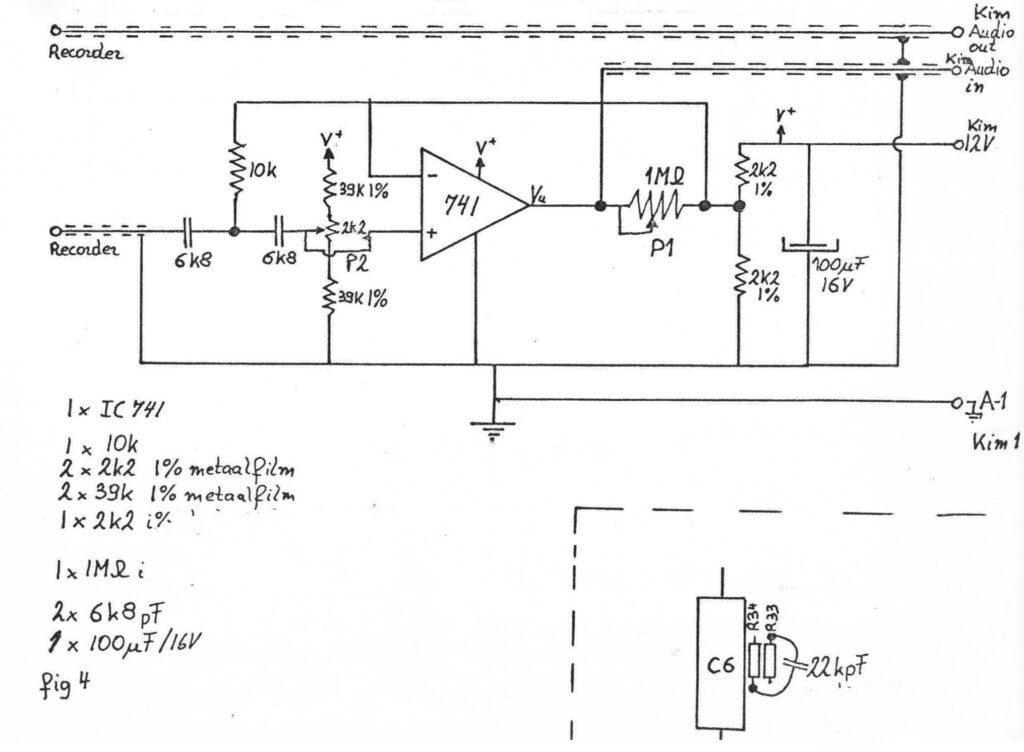
The amplification is controlled with variable resistor P1 from 3 to 100x. A second order Butterworth filter lowers frequencies below 2 kHz to remove mains noise.
Note the shielded cables in the drawing. Be careful to use the indicated ground point, never make a groundloop !
Place the amplifier away from noise sources and the KIM-1, noise will be amplified too!
Insert a 22 nf (22kpF in the drawing) on resistors R33 and R34 (see figure 4 right bottom and Appendix B page B1).
Adjust P2 variable resistor for Vu (output 741 opamp) = 6V
P1 controls the amplification.
The opamp (741) can be any standard general purpose audio type.
Test the amplifier as described above. Adjust for optimal volume. Record a program on tape with lower as usual volume. Try higher volume only temporarily if an error occurs.