
RTK.GPIO protocol
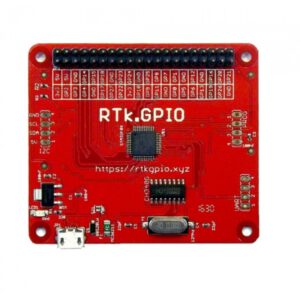
The RTK.GPIO is a microprocessor system with a serial interface, and a RPi 40 pin GIO connector.
USB – CH340 UART – STM cpu – RPi GPIO 40 pin
– power 3.3V via voltage regulator for CH340, STM and RPi GPIO
– power 5V to RPi GPIO
The RPi is electrical identical to the RPi (all signals at 3.3V I/O).
Of the RPi connectors the following is supported:
– GPIO connector, layout identical to Raspberry
– GND, +5V, +3.3V
– GPIO 0-27 I/O set for read, write, pullup pulldown
– I2C on GPIO 2 and 3 100kHZ smbus subset
– No SPI, no ALT functions, no PWM, no edge triggered interrupts, no UART/T etc
– I2C also in separate 4 pin connector with +5V, unsure if 3.3V or 5V I2C signals
– UAR/T connector 4 pin undocumented
– PROG connector undocumented
Serial protocol (based upon studying the firmware source main.cpp version RTk-2016-01-05-FINAL)
A simple and not very robust protocol, no ACK’s, just one error message E1, no complete error checking,
version command returns string without CRLF
– ASCII character based
– The CH340 and STM communicate serial over 230400 baud, no hardware or software handshake
– no block I/O, all GPIO via separate commands
– just one error message ‘E 1 CR LF’
– all can be tested with a serial terminal emulator like Putty etc for GPIO, all is readable ASCII
– I2C commands are readable ASCII, but the data characters are interpreted as 8 bit numbers
(no software handshake allowed!)
Physical:
– GPIO numbers are the numbers on the RPi I/O connector.
– I2C is on GPIO2, GPIO3 with pullup resistors
After power on
– the RTK.GPIO sends the string ‘RTk.GPIO Ready’ (no CR LF!)
– all GPIO are Digital InOut
The RTK.GPIO accepts the following commands.
A command is one character followed by one or more characters as arguments, everything is in ASCII.
Flow:

main flow

repeat
  read(command_char)
  if command char in [A..Z] then
    read (param_char)
    do_command(command_char, param_char)
  else if command_char in [a..|] then
    read(gpio_char)
    gpio(command_char, gpio_char)
  else if command_char in {CR, LF)
    do nothing
  else
    send E1 CR LF
  until forever

do_commmand(command_char, param_char)

  case
    V : send RTk.GPIO Ready (note V requires a second char, can be any!)
	G : read(gpio_char)
	    do_GPIO(param_Char, GPIO_char)

    I : do_I2C(param_char)


gpio_command(pinc, cmdch)

GPIO Commands are two characters.
  pinch,cmdch

pinch is the pin character (a..) where a represents pin 0 (28 I/Os)
character is converted to number (nr = pin character - a)
cmdch is the command to perform on that pin:
  I: Set this pin to a digital input,        eg: aI
  O: Set this pin to a digital output,       eg: aO
  0: Write a digital low to this output,     eg: a0
  1: Write a digital high to this output,    eg: a1
  U: Write a pull input high,    eg: aU
  D: Write a pull input down,    eg: aD
  N: write a pull none           eg  aN
  ?: Read the state of this digital input,   eg: a?
     State is returned as pinch + state(0|1)
     with CR LF added                        eg: a0 CR LF

 error if pin character out of range

do_I2C

in i2c all data chars are interpreted as integers,
0 is decimal i2c address 48 for example
(make sure software handshake is off, otherwise the serial communication eats xon/xoff)

  read(i2c command)
  if i2c command = W; then
    read(i2C_address)
    read(length of i2c datastring)
    read all i2c datastring into i2c datablock array
    i2c.write(i2caddress, i2c datablock, lenght of i2c datablock)
  else if i2c command = R then
    read(i2C_address)
    read(length of i2c datastring)
    read(first datablock data)
    i2c read(i2c address, i2c datablock, i2c datablock length)
    for all in i2c datablock do
      write datablock[count] to serial