Technical specifications
– Built-in full sized QWERTY keyboard
– 20 character alphanumeric LED display (16 segments)
– Integrated 20 character thermal printer
– 20mA current-loop serial interface (can be adapted to RS232)
– Expansion connector (KIM-1 compatible)
– Application connector with 6522 VIA chip
– 4 KB RAM
– 5 sockets for 4 KB ROM/EPROM chips
Repackaged as OEM product by Siemens as PC100, with German documentation. Hardware identical.
- AIM 65 Manuals
- AIM 65 Revisions and circuit diagrams
- Siemens PC100
- Rockwell AIM 65 books
- AIM 65 Software and ROMS
- AIM 65 Rockwell Hardware
- AH5050 disk, serial, printer interface
- Other AIM 65 Hardware
- AIM 65 keyboard variants
- AIM 65 clones
The AIM memory map is:
$0000-$9FFF: RAM (early Rockwell versions only had $0000-$0FFF on board).
$A000-$AFFF: I/O scratchpad memory; some areas can be made available for more RAM.
$B000-$CFFF: Optional Language ROMs (BASIC, Forth, PL/65, Pascal).
$D000-$DFFF: Optional Assembler or Mathpack
$E000-$FFFF: Firmware and monitor program
Rockwell produced the AIM 65 until 1985, and manufactured by Dynatem under license in early 1986 after Rockwell had ceased production. Though the Revision 4 AIM 65 is quite similar to earlier iterations, the subsequent Revision 5 hardware features a redesigned clock generator and support for newer RAM and ROM IC types which became available over the production lifespan of the AIM 65. Relative to Rockwell-manufactured examples, the Dynatem AIM 65 is quite rare. See the Manuals and Software page for circuit diagrams revisions.
Hardware bug on pin Z
There is a hardware bug in early AIM-65 boards. The problem was in rev 1 and rev 0 AIM boards, and it was definitely fixed on rev 4 boards Basically the RAM_R/W signal (pin Z on the Expansion connector) had the inverted Phase 2 clock NAND’ed with R/W. The SYM and AIM were both supposed to follow the KIM standard, but Rockwell got this one signal wrong.
Please note that this has to be solved in e.g. RAM expansion boards by generating this signal the correct way.
Scott Baker’s Rockwell AIM-65 Projects
Designs for FDC, Display, 1541 interface, RS232
* display/ … AIM-65 display adapter board
* rom-scott/ … Multi-banked ROM file for display board
* backplane/ … various backplane boards. Needed to place the display board on top of the AIM-65.
* tape-rs232-c1541/ … application board for tape, RS232, and commodore 1541 AH5050. Largely untested.
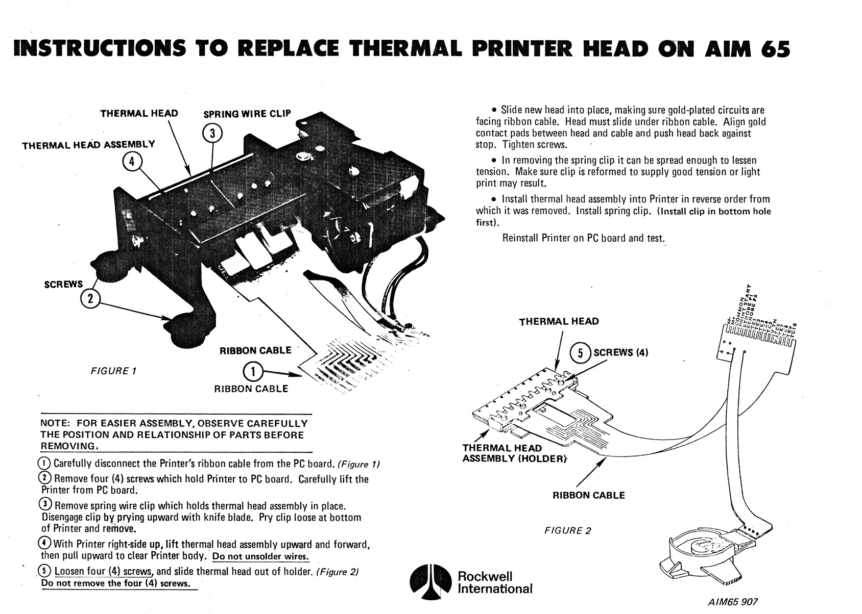
Replace Printer head
See the articles on the MC-65, a AIM 65 compatible system by the German magazine MC Die Microcomputer-zeitschrift