AIM 65/SYM-1/KIM_1 expansion boards were available: the excellent Corsham Technologies boards offer RAM/EPROM/I/O with modern SRAM (low power, low IC count) in kit or assembled format. Here are the boards offered, I use them on my MOS KIM Reproduction KIM and SYM-1 and AIM 65.
First the current available boards, later the older boards
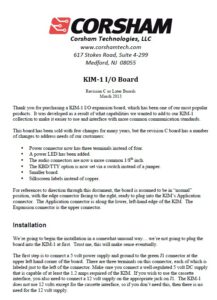
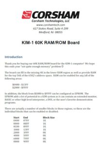
KIM-1 RAM/ROM 60K board
This is a combination RAM and EPROM board with a fair amount of flexibility for adding more functionality to your KIM-1!
Features:
Fills in the KIM’s missing RAM from $0400 to $13FF, giving you 5K from $0000 to $13FF.
Has RAM from $2000 to $FFF7, selectable in 8K segments.
The top 8K ($E000 to $FFFF) can optionally be replaced with 8K of EPROM on the board (27C64 EPROM).
Includes the xKIM extended KIM-1 monitor by default.
The xKIM monitor has commands to load hex files, dump and edit memory, a memory test, plus commands to access SD card features from our SD Card System.
The extended monitor has vectors to command functions so programs written for it won’t break when new versions are introduced.
This board can be added to any KIM-1 system, but the easiest way to add it is with our I/O Board. This board comes with a ribbon cable that plugs right into the I/O Board with no mess. By default the DIP switches are set so your KIM will have 5K of RAM from $0000 to $13FF and from $2000 to $DFFF. The extended monitor is from $E000 to $FFFF.
 |
KIM 60K RAM ROM Manual |
 |
Schematic KIM 60K RAM ROM board Memory test program |


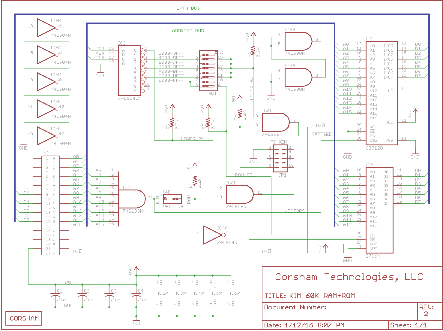
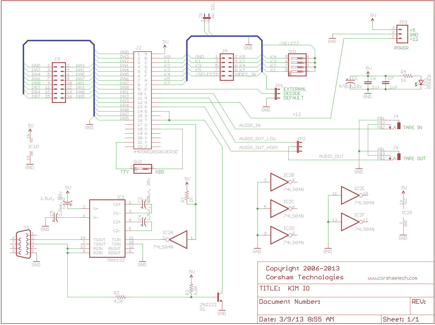
KIM-1 I/O board
 |
KIM I/O manual Rev C |
 |
Schematic KIM I/O board |
The KIM-1 Application connector has a lot of useful signals on it and our expansion board makes them easily usable, as well as providing an RS-232 interface to the KIM’s serial port. The KIM has a 20 ma loop interface because that was the standard used by mechanical teletypes commonly used as terminals in the early days of the microcomputer revolution. Now we all have RS-232 ports on our computers and our I/O board allows a modern computer to connect to the KIM.
The expander plugs into the KIM’s Application connector. The lower left hand side of the board has a DB-9 connector that mates with a standard cable to a PC serial port.
Just above the serial connector are two standard 1/8″ inch audio connectors for a tape player; some people still like saving data to tape, just like in the old days. If both cables are out then the audio in/out lines are connected; this is perfect for running PLL adjustment programs. There is a jumper to select whether to use the audio high or low connections.
Above the audio connectors is the power connector with connections for +5, +12 (only needed if the cassette interface is used) and Ground. A filter capacitor is present to keep the voltages smoothed out.
Two of the best additions to this board are the POWER LED and KBD/TTY switch. A few people, myself included, have almost pulled board or made other changes while power was on. The handy LED provides an indication that 5 volts is present.
If you’re switching back and forth between the normal KIM KBD operation and using an external TTY device, there is now a small switch located on the board that is clearly labeled as to which position is for KBD and which is TTY.
There are various connectors and a set of switches provided for feeding the K1-K4 lines to an external memory board, such as our 4K or 60K memory boards. Each K* signal is individually selected, so if you have peripherals in any of the K1-K4 banks, you can disable any of those signals from going to the external board.
All of the remaining I/O lines are brought to a header for expansion.
KIM-1 6530 Replacement board
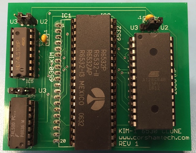
A very common problem with maintaining 40 year old computer systems is that some of the parts have not been made for many decades, such as the two 6530 chips on the KIM-1. Each contains several timers, 64 bytes of RAM, multiple parallel I/O ports and 1K of mask programmed ROM containing the KIM-1 monitor program. To make things even more complicated, each 6530 is mask programmed with a number of configuration options such as which interface pins and address lines select which internal devices.
Many people, Bob included, have at least one KIM-1 in their collections with a non-functioning 6530. Depending on what failed, the KIM might be quite usable, completely unusable, or someplace in between. For these people, there was little chance of ever fixing the problem because the two 6530s in the KIM are unavailable anywhere… not even on eBay! In an effort to fix his own KIM, Bob borrowed work of other people and developed a small board that can replace either 6530 on a KIM-1.
Basically this emulates the functionality of the non-functioning 6530 by using the I/O ports, RAM, and timers from the 6532 chip, and then having an external EEPROM hold the code that was in the ROM of the original chip.
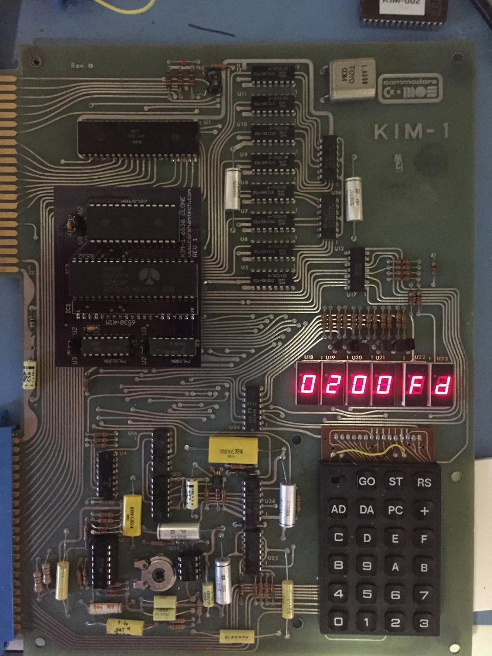
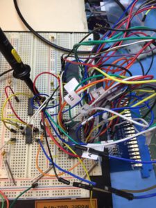
The board replaced U2 (6530-002) on Bob’s KIM and produces a fully functional system again. This is a prototype board (strange board color) but is identical to the production version otherwise.
For full documentation, schematics, design files, Gerbers, EAGLE CAD files and other technical data please also see Bob’s development notes.
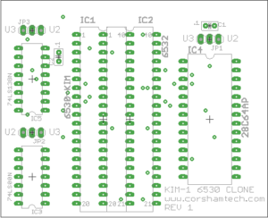
The assembled version is the quickest way, and the easiest. Just set the three jumpers to either U2 or U3 to indicate which chip you’re replacing, remove the old 6530, then plug in this board. Bob strongly suggest saving the original 6530 in case you ever decide to sell your KIM to a museum as a static display.
 |
KIM-1 6530 Replacement board manual |
 |
KIM 6530 technical notes |
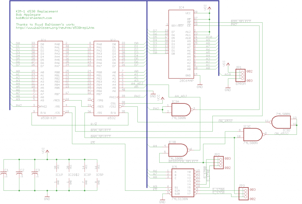 |
Schematic KIM-1 6530 replacement |
 |
kim-1 6530 design: gerbers, eagle, KIM ROM |
AIM 65/SYM-1 60K RAM
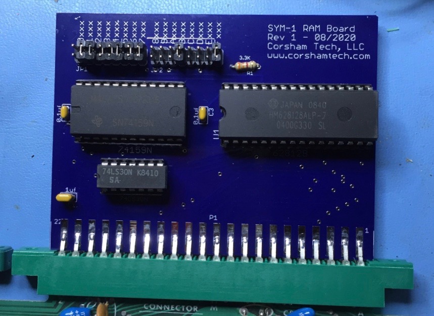
Basic features of the board:
- Can be used on either a SYM or an AIM.
- Memory selectable on 4K boundaries covering the entire 64K address space. Not all blocks can be RAM, as the SYM-1 already has up to 4K of RAM on-board, there are multiple ROM sockets, and I/O.
- The top $80 bytes are not available; that area is reserved by the SYM-1.
- Can allow space for BASIC or other software in ROM. My system has an 8K BASIC ROM so I did not place RAM at C000-DFFF.
The Rev 2 boards have an additional chip which works around a bug in early AIM-65 boards. We know the problem was in rev 1 and rev 0 AIM boards, and it was definitely fixed on rev 4 boards, but I don’t know exactly which revision fixed the problem. Basically the RAM_R/W signal (pin Z on the Expansion connector) had the inverted Phase 2 clock NAND’ed with R/W. The SYM and AIM were both supposed to follow the KIM standard, but Rockwell got this one signal wrong.
Rev 2 boards have replaced the jumpers with a pair of 8 position DIP switches; those are easier to set and there are no jumpers to get lost ??
When running the ROM BASIC, this is what gets displayed:
MEMORY SIZE?
WIDTH?

 32255 BYTES FREE

BASIC V1.1
COPYRIGHT 1978 SYNERTEK SYSTEMS CORP.
Here RAM is configured from 1000-7FFF, B000-BFFF, and F000-FF7F. That gives a lot of room to squeeze in useful add-ons to the monitor.
 |
SYM-1 AIM 65 60K RAM manual |
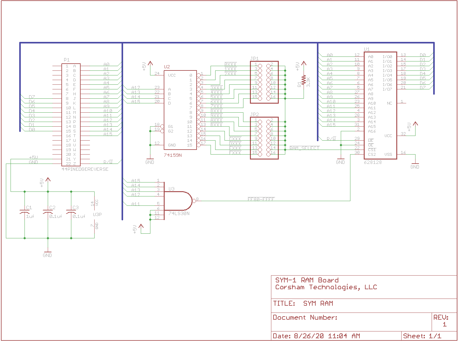 |
Schematic V1 |
 |
Schematic V2 |
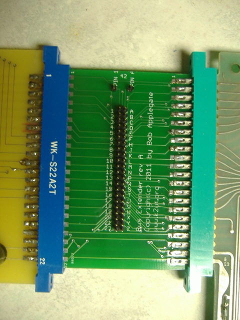
22/44 pin Extender Board
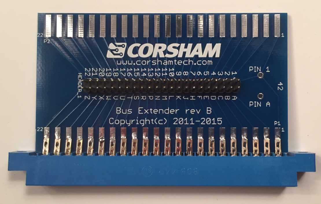
One side has a 22/44 connector ready to plug into your KIM or any other computer with 22/44 edge connections on .156″ centers. On the other side are the same pins for you to plug another board into.
In the middle is the cool stuff. All pins brought to a .1″ center header, and each is labeled so you won’t forget that some letters aren’t used ??
There are a couple of good uses for this extender. First, you can easily probe any signal between the KIM and add-on board. Nice. The other big plus is that it saves wear and tear on the edge connectors of the KIMs in our lab. They are almost 40 years old, so we try to be gentle on them.
An older version in use in our workshop…
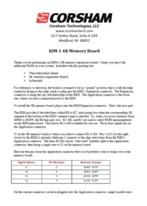
KIM-1 4k Memory board
Not available anymore. A very simple board to add 4K RAM to lower address space ($0400-$13FF
 |
Manual KIM-1 4K RAM board |
 |
Schematic 4k RAM Board |
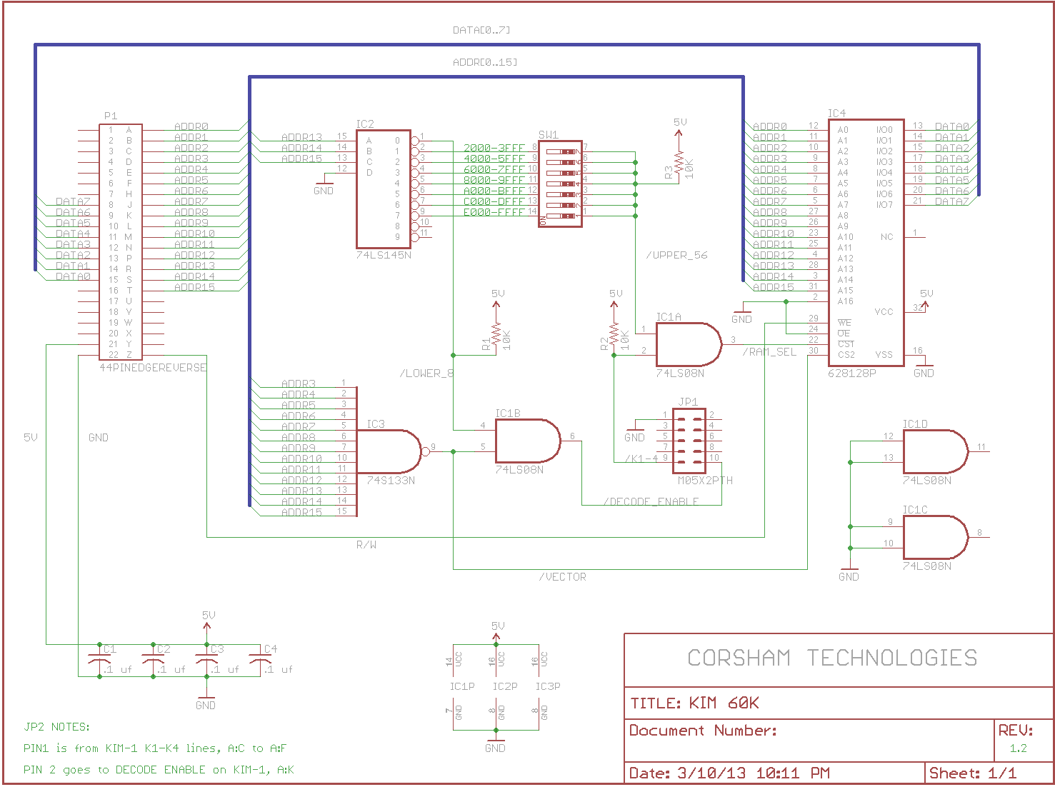
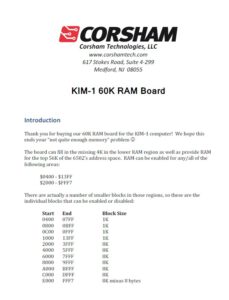
KIM-1 60K RAM board
Not available anymore. A forerunner of the 60K RAM ROM.
1
 |
KIM 60K RAM Manual |