On this page:
Schematics, Manual & Binaries
Upgrading a KTM2 to a KTM2-80
Upgrading the KTM System Boot ROM
Changing the Character ROM
Pictures of homebuilt KTM
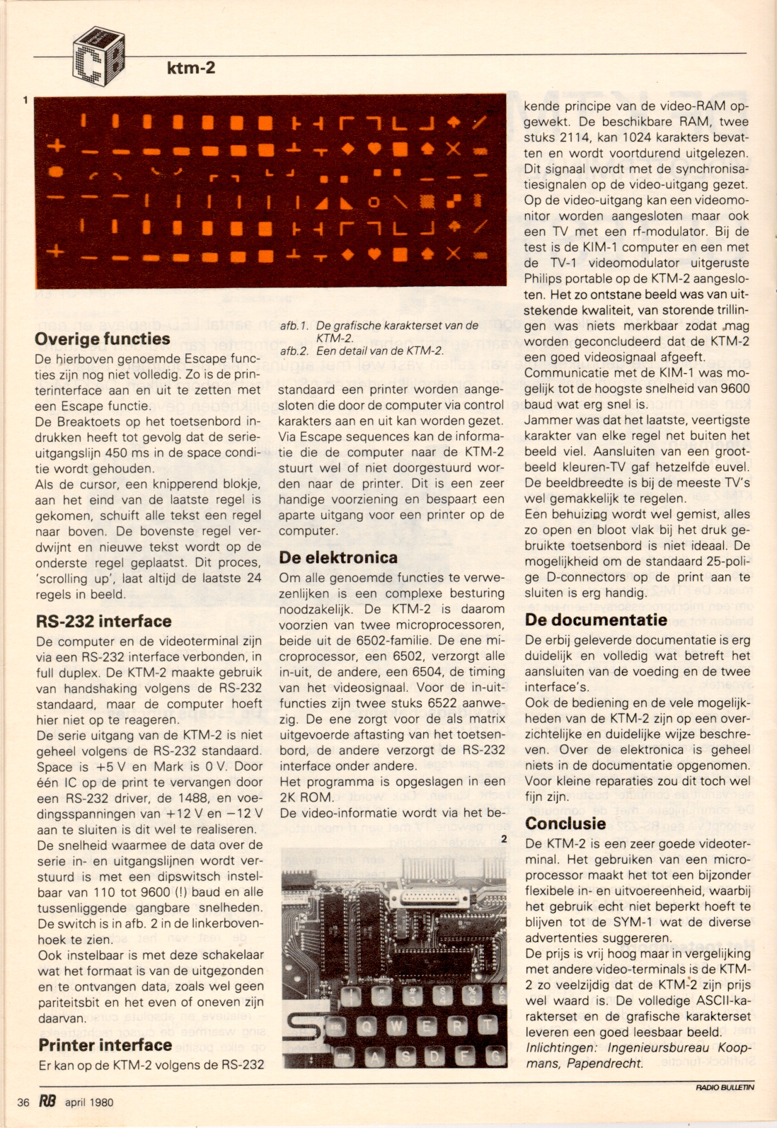
Dutch article about the KTM-2 by Hans Otten
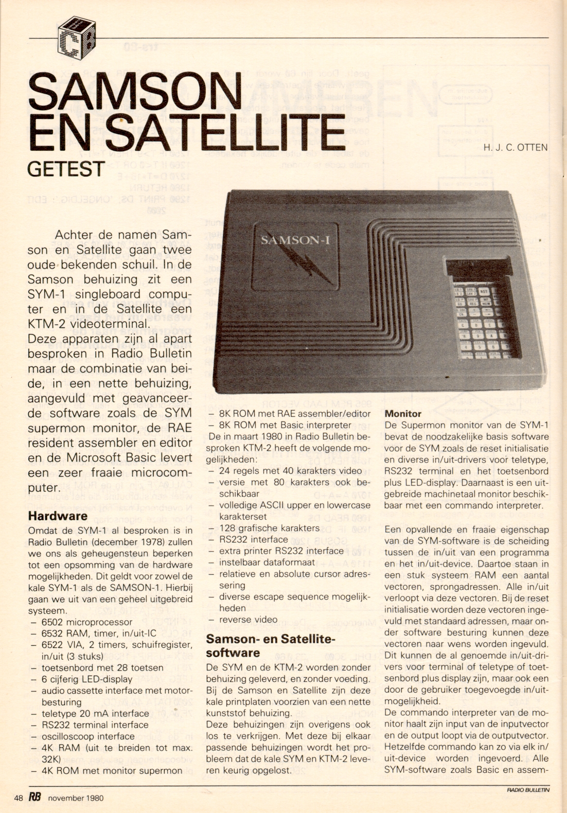
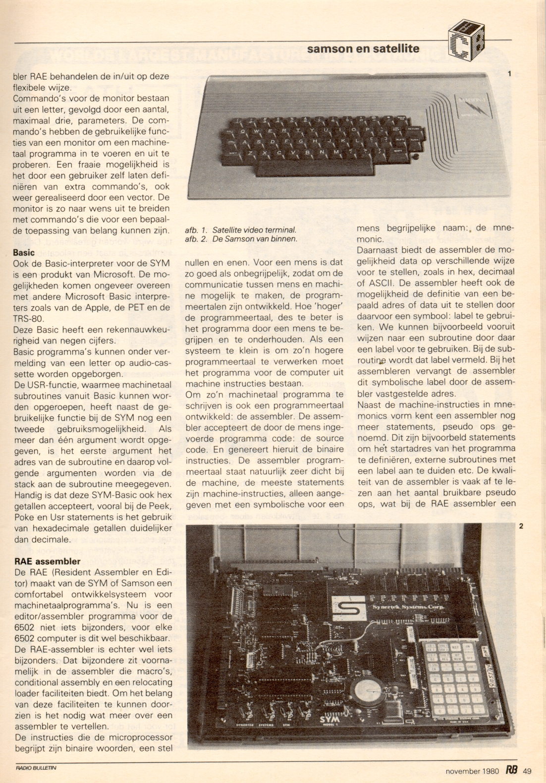
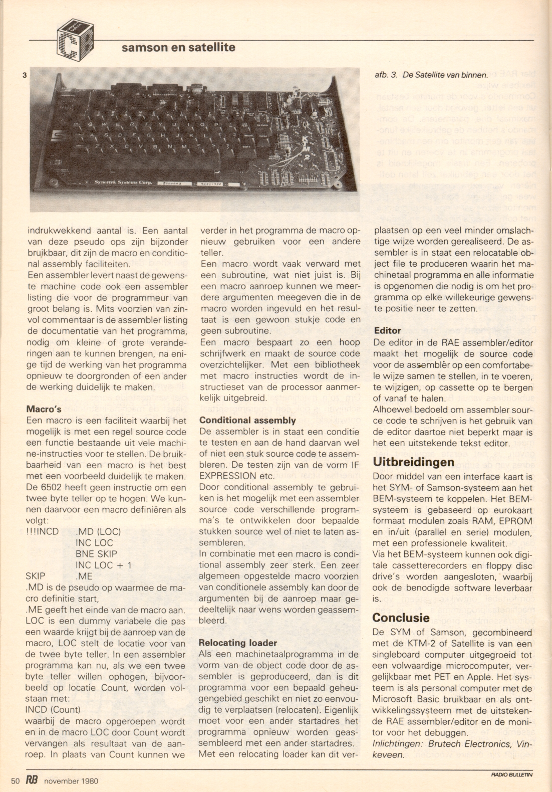
Dutch article about the Samson, a cased SYM-1 and KTM-2, by Hans Otten
 General Description
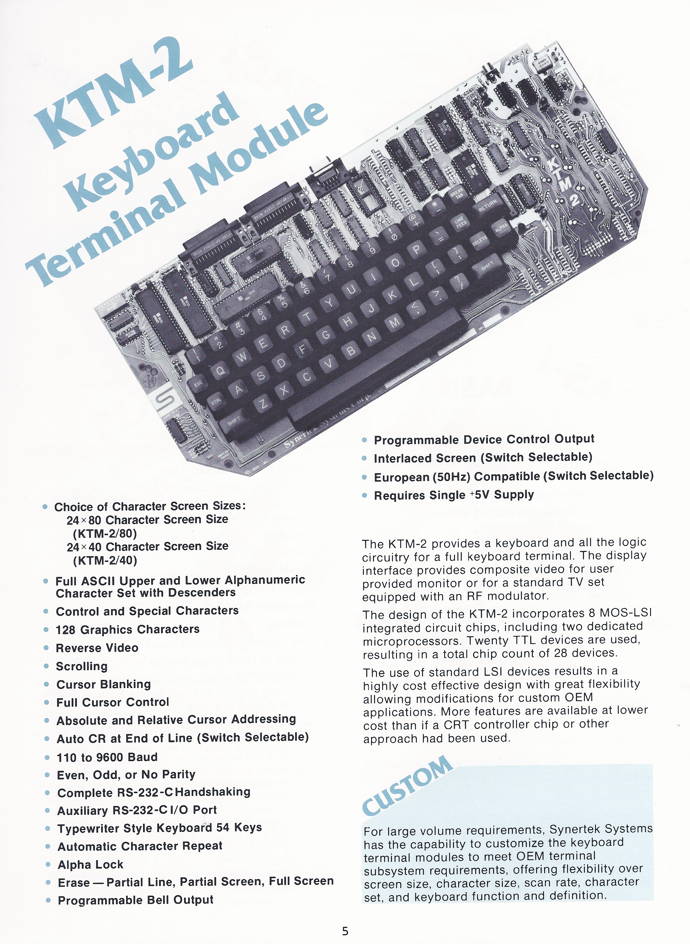
The KTM-2 came in two models. The standard KTM-2 with its low video frequency (2.6MHz) can use ordinary home TV as a video monitor. This helped keep the user system cost low. The KTM-2/80 has twice the displayable characters; however it must be used with a video monitor since the 80 character lines have a higher frequency (7.2MHz). The KTM-2/80 is functionally identical in every respect with the KTM-2. Throughout the remainder of this article, KTM-2 will refer to both the KTM-2 and the KTM-2/80 unless otherwise noted.
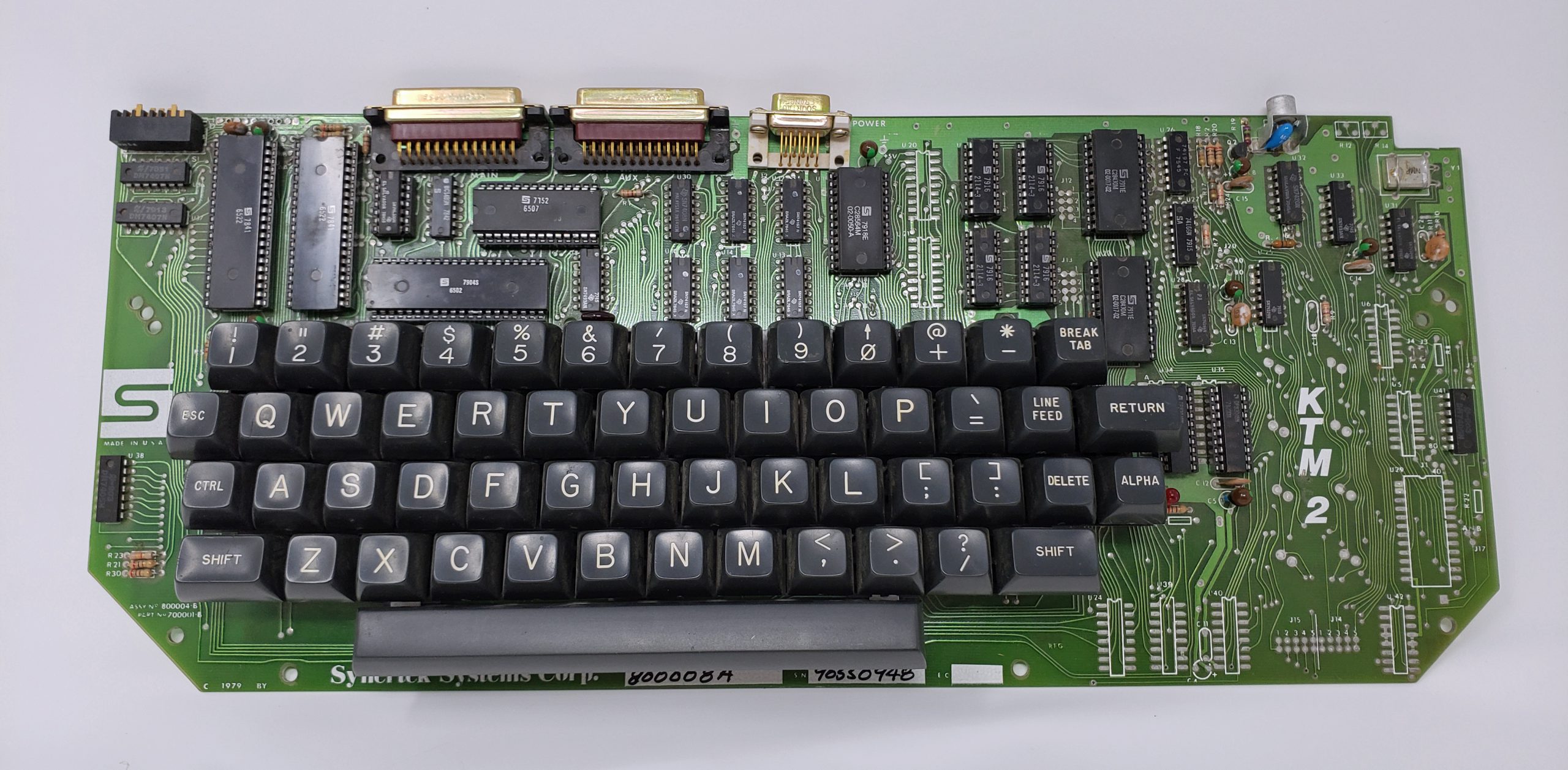
The KTM-2 keyboard consists of 54 keys which generate 128 ASCII characters and 128 graphic characters. The ASCII characters include upper and lower case alpha, numeric, special and control. The graphic and alphanumeric characters can be displayed simultaneously. This is beneficial in business and industrial applications where annotated forms or graphs are desirable. With KTM-2’s relative and absolute addressing, graphs, game pieces, etc, can be placed and/or moved about on the screen with a minimal amount of software.
The KTM-2 has two serial communications ports: the main port used primarily with a computer for information transfer and the auxiliary port used primarily with a printer for hard copy. The serial ports are full duplex allowing information to be transmitted and received simultaneously. The serial format is comprised of a start bit, seven data bits, a parity bit (for detection of transmission errors), and one or two stop bits. The bit transmission rate is selectable from 110 up to 9600 baud. The eight baud rates are selectable by three of the eight option switches. Other switch selectable features are: even, odd or no parity; interlaced or non-interlaced screen; line truncate or line wrap around (to next line); and 60Hz or 50Hz frame rate.
The KTM-2/80 has two microprocessors, a 6502 and a 6507, two 6522 VIA’s, 2K of RAM and 6K of ROM
Schematics, Manual & Binaries
| Complete Manual of KTM-2 and KTM-2/80 1979 low res low quality |
| Manual of KTM-2 and KTM-2/80 February 1981, high quality |

| KTM-2 Schematic KTM-2 |
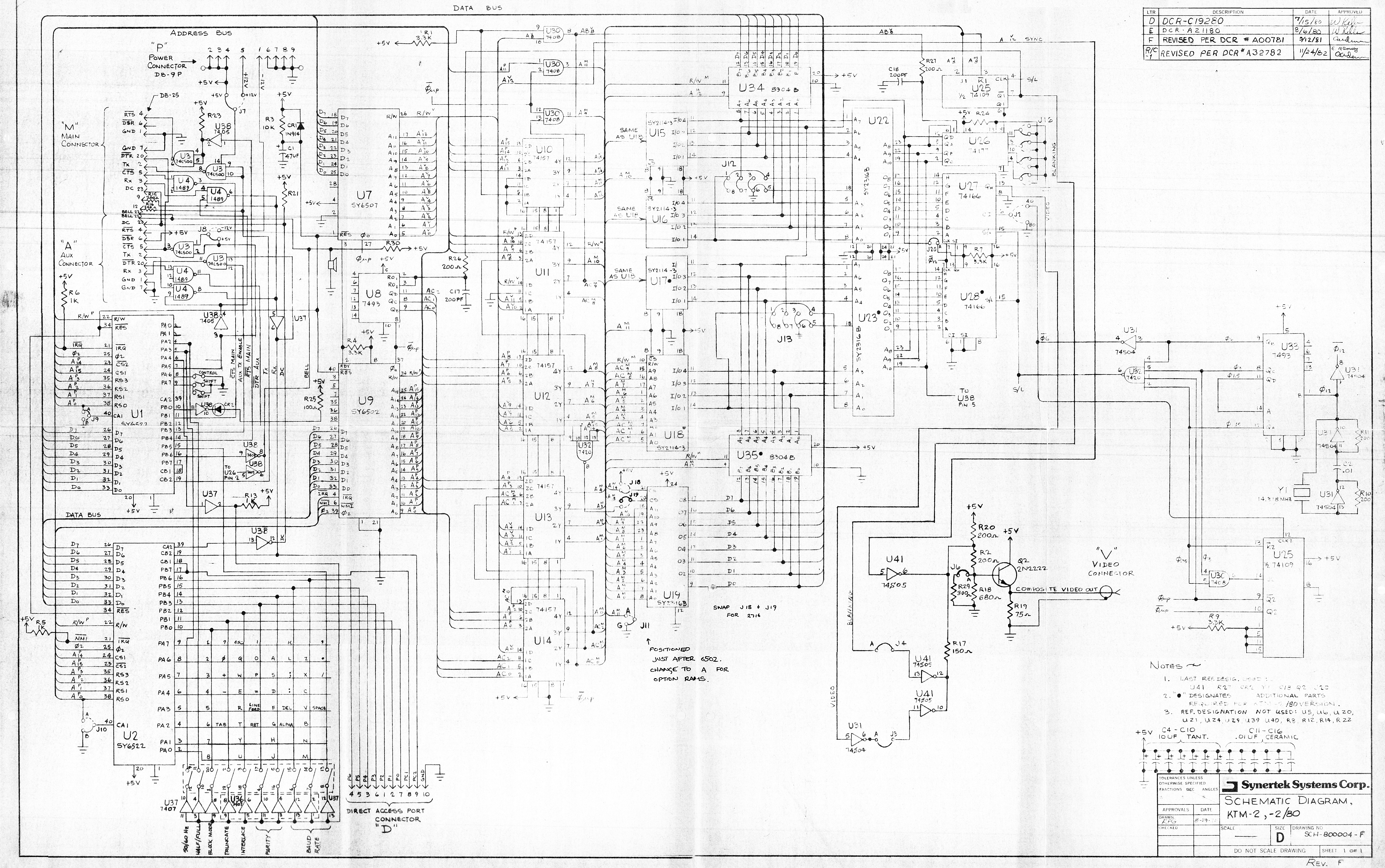
| KTM-2 Schematic KTM-2 original |
The source code with binaries:
NOTE: The 60 key binary files ARE NOT for a standard KTM-2. These files have been modified for a 60 key version the KTM’s 54 key keyboard.
60 Key Boot ROM – Contains altered binaries for KTM2 & 2/80. (2732 – 4K)
60 Key Character ROM – Character generator binaries for above. (2716 – 2K)
54 Key Original Boot ROM – Contains both KTM2 & 2/80 binaries. (2732 – 4K)
54 Key Original Boot ROM – Contains only KTM2/80 binaries. (2716 – 2K)
54 Key Original Boot ROM – Contains original binaries in text format.
54 Key Character ROM – Original 54 Key binaries with change made to cursor from blinking block to blinking line.
54 Key Character ROM – Original 54 key binaries in text format.
Source Code KTM2/80 – Hacked version to allow either original or new boot ROM to be generated in text format.
Source Code KTM2/80 – Same as above but in RAE format.
KTM_2 article
An article I wrote with a review of the KTM-2, in Dutch, in the magazine Radio Bulletin, april 1980

KTM_2 article
An article I wrote with a review of the Samson, in Dutch, in the magazine Radio Bulletin, april 1980. The name Samson was used to name a package of SYM_1 and a KTM-2, both in a nice case, november 1980.
Upgrading a KTM- 2 to a KTM-2/80
With an EPROM programmer available and a little electronics know how, this article will attempt to help the reader upgrade a KTM-2 to a KTM-2/80 terminal. It should be noted that users with KTM-2’s with a serial number prior to 0733 CANNOT perform these modifications. The actual modifications will require you to cut a trace on the board, add a jumper, install 5 IC sockets and chips, and replace the existing system ROM. You will also have to change some other jumpers to accommodate the new system and character EPROM depending on what EPROM you use. I personally changed the original 2 K system ROM with a 2732, 4 K EPROM. The lower half of the 2732 contains the KTM-2 code and the upper half contains the KTM-2/80 code. I used a 2716 EPROM for the character generator and no modifications were necessary to the board. The 2716 and original character ROM in the KTM-2 have identical pin outs. U-22, the original character generator is simply duplicated for U-23. By adding a DPST switch, you would be able to switch between either the 40 or 80 KTM-2 system modes.
The files located here contain the binaries for both system and character ROMS that I currently use and the original KTM ROM’s. My ROM’s have been changed to accommodate the 60 key keyboard I currently use instead of the KTM-2’s 54 keys. The system ROM mapping for the keyboard matrix was changed to reflect these new keys and the character ROMS were also altered for these changes. NOTE – the 60 key binary files will not work with any original KTM-2 or KTM2/80 as the keyboard encoding mapping has been altered for my keyboard. You may also download the source code.txt or using the SYM Link program, download the source code.rae file and assemble the code to generate your own boot ROM. If you decide to download the binaries you can click here to find out how to re-map the keyboard matrix. Assuming you have an EPROM burner, you can always copy your original character ROM (U-22) and burn a duplicate that will be needed for U-23. If you want to change the blinking block to a blinking line, download the original binaries with the modification already made for you. You will also need four chips to complete the upgrade. They are 1 – 74166 (U-28), 2 – 2114 (U-17 & 18) and 1 – 8304 (U-35). You may also consider putting in sockets instead of soldering the chips directly into the board.
The first step will be to cut a trace on the KTM-2 board. The trace is located to the right of U-27 and should be labeled J-2. This trace goes between the marked J2 location and the number 40. Your board may have a jumper installed or the trace. After cutting the trace a jumper needs to be installed between the J2 location and the number 80 hole. If you decide you want to switch between the 40 or 80 character mode, click here or simply install the jumper. Once this is completed, it is now necessary to install the IC sockets and chips. You will have to change other jumpers to properly chip select your particular EPROM. A complete schematic, located here, will help you locate these jumpers. If you decide to copy your original character ROM, do so and then install it in the U-23 socket. Install the balance of the IC’s. The last thing to consider is what boot ROM you want. If you only want the -80 code, simply download the 2K binaries and burn the chip. If you decide to dual-ize the KTM, download the 4K version. In either case, jumpers will have to be re-arranged to accommodate the new chip.
Be sure to double check your work as I cannot be held responsible if it does not work properly. I can say that I have done the above procedure and had no problems of any kind.
The following jumper changes will complete the upgrade. I am not sure of the original jumper location default setting as I no longer have my original KTM. I do know the original character generator ROMS have identical pin outs of the 2716. The boot ROM on the other hand is a different story as pins 20 and 21 are both positive chip select and that pin 18 was grounded. The chart below will show what jumpers to change and what to make them depending on the EPROM.
Pin # 2716 2732
18 J-11 J-11 Connect to pin 8 of U-32 (should be one connection at J-19)
20 J-19 J-19 Connect to ground (should be “G” on board at J-11)
21 J-18 see note For 2716, connect to +5 volts located at J-18.
NOTE: If dualizing the KTM connect pin 21 ( A-11 ) to common of switch as shown here. If pin 21 is low, the lower half of the 2732 is selected and if high, the upper half is selected. The lower half will be the KTM-2 and the upper half will be the -80.
Upgrading Synertek Systems KTM-2 to a KTM-2/80
With an EPROM programmer available and a little electronics know how, this article will attempt to help the reader upgrade a KTM-2 to a KTM-2/80 terminal. It should be noted that users with KTM-2’s with a serial number prior to 0733 CANNOT perform these modifications. The actual modifications will require you to cut a trace on the board, add a jumper, install 5 IC sockets and chips, and replace the existing system ROM. You will also have to change some other jumpers to accommodate the new system and character EPROM depending on what EPROM you use. I personally changed the original 2 K system ROM with a 2732, 4 K EPROM. The lower half of the 2732 contains the KTM-2 code and the upper half contains the KTM-2/80 code. I used a 2716 EPROM for the character generator and no modifications were necessary to the board. The 2716 and original character ROM in the KTM-2 have identical pin outs. U-22, the original character generator is simply duplicated for U-23. By adding a DPST switch, you would be able to switch between either the 40 or 80 KTM-2 system modes.
The files located here contain the binaries for both system and character ROMS that I currently use and the original KTM ROM’s. My ROM’s have been changed to accommodate the 60 key keyboard I currently use instead of the KTM-2’s 54 keys. The system ROM mapping for the keyboard matrix was changed to reflect these new keys and the character ROMS were also altered for these changes. NOTE – the 60 key binary files will not work with any original KTM-2 or KTM2/80 as the keyboard encoding mapping has been altered for my keyboard. You may also download the source code.txt or using the SYM Link program, download the source code.rae file and assemble the code to generate your own boot ROM. If you decide to download the binaries you can click here to find out how to re-map the keyboard matrix. Assuming you have an EPROM burner, you can always copy your original character ROM (U-22) and burn a duplicate that will be needed for U-23. If you want to change the blinking block to a blinking line, download the original binaries with the modification already made for you. You will also need four chips to complete the upgrade. They are 1 – 74166 (U-28), 2 – 2114 (U-17 & 18) and 1 – 8304 (U-35). You may also consider putting in sockets instead of soldering the chips directly into the board.
The first step will be to cut a trace on the KTM-2 board. The trace is located to the right of U-27 and should be labeled J-2. This trace goes between the marked J2 location and the number 40. Your board may have a jumper installed or the trace. After cutting the trace a jumper needs to be installed between the J2 location and the number 80 hole. If you decide you want to switch between the 40 or 80 character mode, click here or simply install the jumper. Once this is completed, it is now necessary to install the IC sockets and chips. You will have to change other jumpers to properly chip select your particular EPROM. A complete schematic, located here, will help you locate these jumpers. If you decide to copy your original character ROM, do so and then install it in the U-23 socket. Install the balance of the IC’s. The last thing to consider is what boot ROM you want. If you only want the -80 code, simply download the 2K binaries and burn the chip. If you decide to dual-ize the KTM, download the 4K version. In either case, jumpers will have to be re-arranged to accommodate the new chip.
Be sure to double check your work as I cannot be held responsible if it does not work properly. I can say that I have done the above procedure and had no problems of any kind.
The following jumper changes will complete the upgrade. I am not sure of the original jumper location default setting as I no longer have my original KTM. I do know the original character generator ROMS have identical pin outs of the 2716. The boot ROM on the other hand is a different story as pins 20 and 21 are both positive chip select and that pin 18 was grounded. The chart below will show what jumpers to change and what to make them depending on the EPROM.
Pin#  2716  2732
 18   J-11  J-11     Connect to pin 8 of U-32
                     (should be one connection at J-19)
 20   J-19  J-19     Connect to ground
                     (should be "G" on board at J-11)
 21   J-18  see note For 2716, connect to +5 volts located at J-18.
NOTE: If dual-izing the KTM connect pin 21 ( A-11 ) to common of switch as shown here. If pin 21 is low, the lower half of the 2732 is selected and if high, the upper half is selected. The lower half will be the KTM-2 and the upper half will be the -80.
Upgrading the KTM System Boot ROM: Changing the Keyboard Encoder
Please Read Carefully:
A 2316-B ROM contains program codes and the keyboard encoding table. Caution: pins 20 and 21 (unlike 2716’s) are positive chip-select: you need to have them at a high level in order to read the ROM. Exchanging the ROM for a 2716 EPROM requires changing the jumper settings at J-18 and J-19.
The KTM uses two input lines to check the status of the SHIFT and CONTROL keys, and an 8 x 8 matrix for checking the other keys. This lay-out requires 2 * 64 = 128 bytes of storage for decoding the keys in lower-case and upper-case mode. Not all of the 64 cross-points of the matrix are used (the KTM has 51 keys apart from SHIFT and CONTROL). These cross points are decoded by a null code. The KTM control functions ALPHA and BREAK are identified by a dedicated bit (bit 7 = 1, – 0 for all other characters). Bits 6 to 0 contain the ASCII code in reversed order! For instance, the key `8` (ASCII $38) thus encodes to $0E. The keyboard encoding table shown below starts from address $723 up to $7A2 for the KTM-2/80 and $6FA up to $779 for the KTM-2. Standard KTM lay-out is (only lower-case is shown):
     U2  (6522) PA   0   1    2    3    4    5    6   7    ROM addr.
--------------------------------------------------------------------
U2 (6522) PB 0   /   8   7    6    5    4    3    2   1    $ 723-72A
U2 (6522) PB 1   /            TAB       -    +    0   9    $ 72B-732
U2 (6522) PB 2   /   u   y    t    r    e    w    q   ESC  $ 733-73A
U2 (6522) PB 3   /            RET  LF   =    p    o   i    $ 73B-742
U2 (6522) PB 4   /   j   h    g    f    d    s    a        $ 743-74A
U2 (6522) PB 5   /           ALPHA DEL  :    ;    l   k    $ 74B-752
U2 (6522) PB 6   /   m   n    b    v    c    x    z        $ 753-75A
U1 (6522) PB 5   /                SPACE      /    .   ,    $ 75B-762
Creating an original KTM-2 boot ROM mapping table
If you are upgrading a stock KTM-2 to a /80, use the following procedure or just download the original binaries and burn them.
1. Copy your original boot ROM and note what memory address you saved it at. For this example, we will use $6000.
2. Load the binaries here and save these at $5000. This will be a 4K file which includes both KTM files. The lower half ($5000 to $57FF) for the KTM and the upper half ($5800 to $5FFF) KTM-2/80.
3. Copy the table from $66FA to $6779 and paste it into location $5F23 and $56FA. This will now contain your map and will work for both terminals. Using the SYM, type: .B 5F23,66FA,6779 (cr), which will block move everything from $66FA to $6779 to memory location $5F23. Repeat the block move except move to $56FA.
4. Burn the EPROM.
The information given should suffice to change the keyboard according to any desired lay-out. My keyboard now reads and displays the added keys on my new keyboard
Changing the Character ROM
Modifications to the character ROM are simple once you understand the map in the chip. The KTM-2/80 terminal board features a 1920 character display, 24 lines by 80 characters each. The characters – both ASCII and graphics – are represented by a ‘pixel’ of 8 bytes (= 8 * 8 bits), each bit corresponding to a dot on the screen. Since a total of 256 different characters constitutes the KTM’s character font, 256 * 8 bytes, i.e. 2 Kbytes, are needed to store the pixel patterns. The KTM uses two identical 2 K-ROMs (type 2316-B) which are switched to give the high speed necessary for a CRT display.
How are the pixel patterns coded? Page 0 of the ROMs comprises the top line of all the 256 patterns, page 1 the next line, etc., page 7 the bottom line of each. Bit 7 corresponds to the leftmost dot, bit 0, accordingly, to the rightmost one. Therefore, the pattern code for any character is to be found at a fixed lo-byte address (determined by the ASCII code), while the hi-byte of its address varies from 0 to 7. The lo-byte address is exactly the ASCII code of the character (0 to $7F ASCII, $80 to $FF graphics), read backwards! Graphic characters fill the 8-by-8 matrix completely, while ASCII characters leave the left and right margins empty and usually the bottom row, too.
Suppose you want to change the appearance of the ~ tilde ($7E) to `B` (Greek beta). You first invert the ASCII code, reading it from right to left, which gives (in that special case, only, the same code) $7E. This is the lo-byte address. Next, you look up the codes for all the pixel rows, top row first, at address $07E, $17E, … $77E:
    00 00 00 32 4C 00 00 00

Rows 4 and 5 are non-empty, resulting in the following pattern:

row 4:   ..xx..x.
row 5:   .x..xx..    See the wave-form?

Let us now devise the `B`:

row 1:   ..xxx...    = $ 38 at address $07E.
row 2:   .x...x..    = $ 44 at address $17E.
row 3:   .x.xx...    = $ 58 at address $27E.
row 4:   .x...x..    = $ 44 at address $37E
row 5:   .x....x.    = $ 42 at address $47E
row 6:   .xx..x..    = $ 64 at address $57E
row 7:   .x.xx...    = $ 58 at address $67E
row 8:   .x......    = $ 40 at address $77E
These values have to be stored to obtain a beta instead of a tilde for a $7E. Since the KTM character ROMs are pin compatible with standard 2716 EPROM’s, any user with access to an EPROM programming device can alter the screen appearance of all the KTM characters.
In case you don’t like the cursor’s blinking block and prefer a blinking line like I did (I found that block annoying), I’ll help you cheat. The KTM uses location $FE for the blinking block. If you look at your chip, locations $0FE, $1FE, $2FE etc all contain an $FF. Change all the locations to $00 except $7FE. This now changes the annoying blinking block to a blinking line.

I have included some notes and prints showing how and where I added the extra keys for the larger keyboard that work correctly with the above 60 key code. Cross-points circled in blue are the added keys. I also needed to change the existing keys matrix with new ASCII values to correctly display the new ASCII code. Example would be on the original KTM, a shift 2 displays an “, whereas on a normal keyboard the shift 2 is an @ character. These are also shown in the schematic, but are not highlighted. Below is the mapping table showing the binary bites and the corresponding ASCII code generated for both keyboards.
KTM-2 Keyboard Encoding Table. Remember that all bytes are backwards.
IF KEYS-54 (Standard KTM)
 Lower Case Table    *NC = No Connection

    $0E $76 $36 $56 $16 $66 $26 $46
     8   7   6   5   4   3   2   1
    $00 $00 $48 $00 $5A $6A $06 $4E
     NC  NC TAB NC   -   +   0   9
    $57 $4F $17 $27 $53 $77 $47 $6C
     u   y   t   r   e   w   q  ESC
    $00 $00 $58 $28 $5E $07 $7B $4B
     NC NC  RET LF   =   p   o   i
    $2B $0B $73 $33 $13 $67 $43 $00
     j   h   g   f   d   s   a   NC
    $00 $00 $F2 $7F $2E $6E $1B $6B
     NC NC APL DEL  :    ;   l   k       (ALP = ALPHA)
    $5B $3B $23 $37 $63 $0F $2F $00
     m   n   b   v   c   x   z   NC
    $00 $00 $00 $02 $00 $7A $3A $1A
     NC NC NC   SPC NC   /   .   ,

 Upper Case Table

    $0A $72 $32 $52 $12 $62 $22 $42
     (   '   &   %   $   #   "   !
    $00 $00 $FB $00 $2A $01 $3D $4A
     NC  NC BRK  NC  *   @   ^   )
    $55 $4D $15 $25 $51 $75 $45 $6F
     U   Y   T   R   E   W   Q  ESC
    $00 $00 $03 $3F $1D $05 $79 $49
     NC  NC RET  LF  \   P   O   I
    $29 $09 $71 $31 $11 $65 $41 $00
     J   H   G   F   D   S   A   NC
    $00 $00 $5F $7D $5D $6D $19 $69
     NC  NC ALP DEL  ]   [   L   K
    $59 $39 $21 $35 $61 $0D $2D $00
     M   N   B   V   C   X   Z   NC
    $00 $00 $00 $1F $00 $7E $3E $1E
     NC  NC  NC SPC  NC  ?   >   < IF KEYS-60 (Modified KTM) Lower Case Table $0E $76 $36 $56 $16 $66 $26 $46 8 7 6 5 4 3 2 1 $08 $03 $48 $20 $5E $5A $06 $4E BS ` TAB ^B = - 0 9 (^B = Repeat Key*) $57 $4F $17 $27 $53 $77 $47 $6C u y t r e w q ESC $6F $1D $58 $28 $6D $07 $7B $4B { \ RET LF [ p o i $2B $0B $73 $33 $13 $67 $43 $00 j h g f d s a NC $00 $00 $F2 $7F $72 $6E $1B $6B NC NC CLK DEL ' ; l k (CLK = Caps Lock) $5B $3B $23 $37 $63 $0F $2F $00 m n b v c x z NC $FB $00 $00 $02 $00 $7A $3A $1A BRK NC NC SPC NC / . , Upper Case Table $2A $32 $3D $52 $12 $62 $01 $42 * & ^ % $ # @ ! $08 $3F $FB $20 $6A $7D $4A $0A BS ~ TAB ^B + _ ) ( (^B = Repeat Key*) $55 $4D $15 $25 $51 $75 $45 $6F U Y T R E W Q ESC $5F $1F $03 $3F $5D $05 $79 $49 } | RET LF ] P O I $29 $09 $71 $31 $11 $65 $41 $00 J H G F D S A NC $00 $00 $F2 $7F $22 $2E $19 $69 NC NC CLK DEL " : L K $59 $39 $21 $35 $61 $0D $2D $00 M N B V C X Z NC $FB $00 $00 $02 $00 $7E $3E $1E BRK NC NC SPC NC ? >     <
* I generate a ^B for the repeat key, but you could generate any key you want.The schematic showing the added keys for the 60 key keyboard is located here.
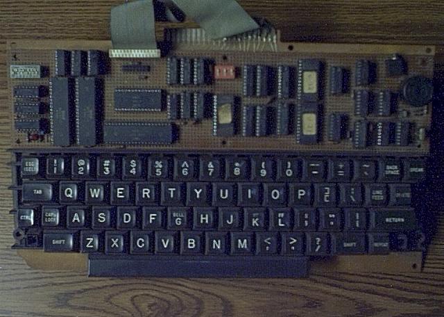
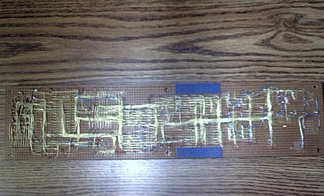
Homebuilt KTM-2/80
Below are some pictures showing a KTM-2/80. Build this on a Radio Shack ASCII keyboard encoder picked up at a flea market. All that was needed was to build the KTM in the space provided above the keyboard, cut the traces for the KTM’s matrix, and install a connector between the keyboard and the KTM board.
First picture shows KTM assembled. Actual board size is 3″ x 13″.
Bottom of keyboard showing trace cuts and wires added for new matrix. What made this easy was the fact that each switch was labeled with its function.
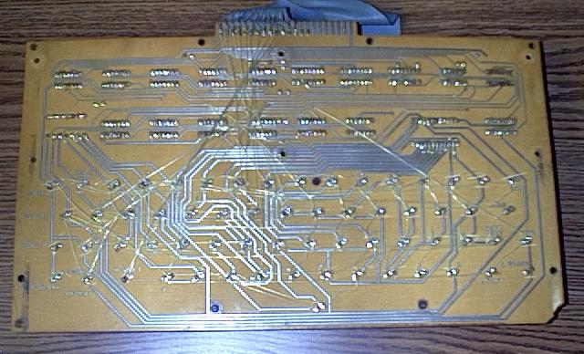
Picture showing bottom of KTM. Point to point wiring using 30 gauge wire is used to save height space and looks much neater. Had to glue two boards together for the 13″ length. The two blue boards shown below are were the joint was made.
Current consumption of the board with all chips on board is about 270mA … that is without any external connections to VIA chips ..
There is a slight mod …looking at the above schematic ..pins 18 and 13 have to be swapped ..that is pin18 becomes !a9 and 13 becomes crtout… reason being the the default schematic for the gal chip had pin 13 as i/o pin … but it is only an input pin ..!!!
PLD file to make it all work ….
Name            SYM-1 Maxi;
Partno          0001;
Revision        ver4,monitor,basic,RAE ;
Date           23/11/17;
Designer        mc;
Company         mcoz;
Location        oz;
Assembly        manual;
Device          g22v10;

/** Inputs **/
pin [3..8] = [a15..10] ;
pin 1 = phi2;
pin 2 = rnw;
pin 9 = a9;
pin 10 = a8;
pin 11 = a7;
pin 13 = crtout;
pin 16 = crtin;

/** Outputs **/

pin 14 = !nr;
pin 15 = !nw;
pin 22 = !cs6532;
pin 18 = !na9;
pin 20 = !via2cs;
pin 21 = !via1cs;
pin 23 = !csram;

pin 19 = !ncrtin;
pin 17 = !ncrtout;

/** Declarations and Intermediate Variable Definitions **/

field ioaddr= [a15..7];
cs6532_eqn   = ioaddr:[A4XX..A7XX];
csrom_eqn   = (ioaddr:[80XX..8FXX])#(ioaddr:[B0XX..FFXX]) ;
csram_eqn   = (ioaddr:[00XX..7FXX]) ;

/** Logic Equations **/

ncrtout=crtout;
ncrtin=crtin;
na9=a9;
nr = phi2&rnw ;
nw  = !rnw&phi2 ;
cs6532 = cs6532_eqn ;
csrom = csrom_eqn&nr;
csram = csram_eqn#csrom;
You can source all binary files from 6502.org or try this combined file that has
Monitor imaged @8000-8FFF and F000-FFFF
Basic imaged from C000-DFFF and
RAE imaged @B000-BFFF and E000-EFFF
Photos by Ray Holt