Though this site is not about home computer systems, but about small SBC’s, it is nevertheless interesting to look at the Atari 850 system.
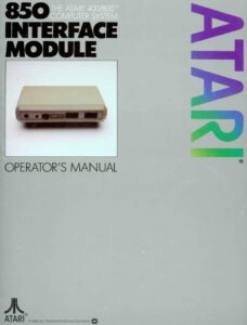
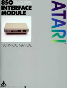
Atari produced the 850 Interface Module to provide access to devices complying with two important interface standards of the time, RS-232-C serial and Centronics parallel.
Four serial interfaces, one parallel interface in self contained case, with its own power supply. Connected to the Atari via the standard SIO cable.
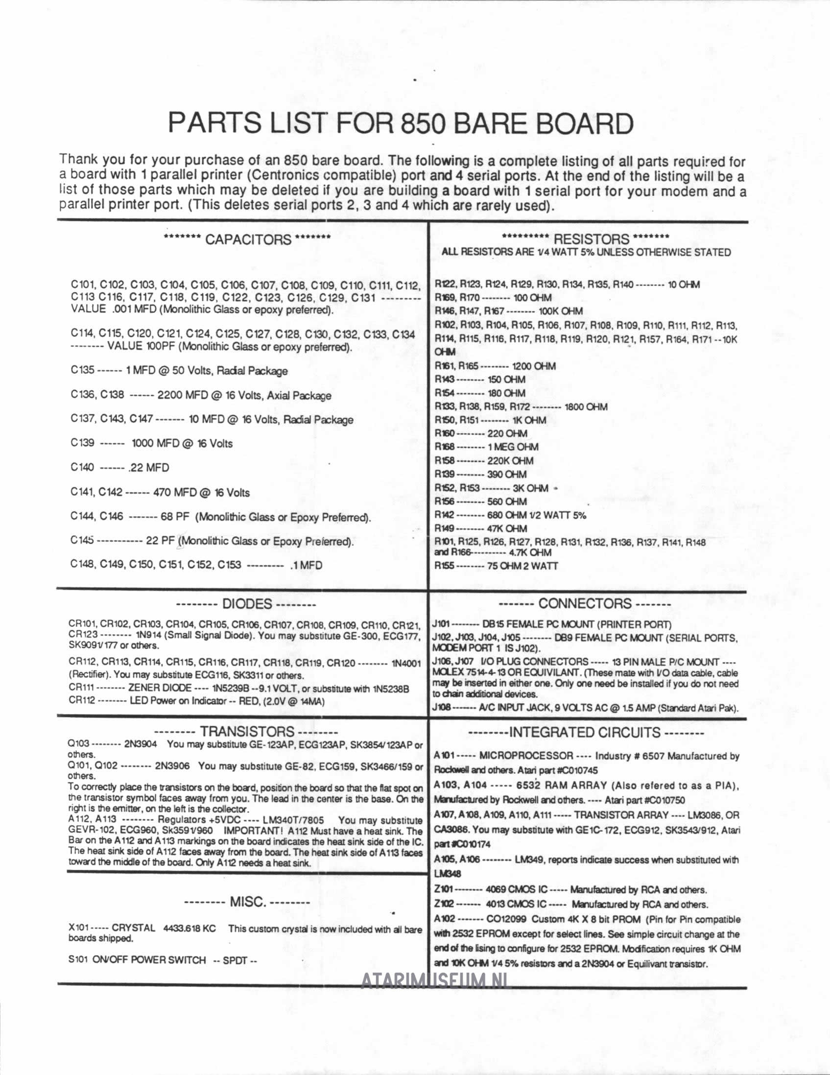
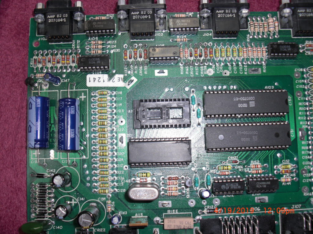
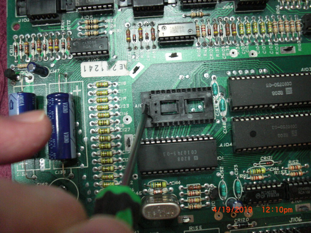
When you look into the system you discover it is actually a simple microprocessor system. The heart is a 6507 CPU, the serial and parallel lines are built with two 6532 IC’s, a ROM with the software.
Serial interfaces and the 6532? This means bit banging.
So this fits well in the theme of small SBCs!
I show you here the circuit diagram, operator, service and technical manual and the sources/binaries of the ROM.
While the Atari's SIO and controller ports did not conform to established
industry standards, Atari produced the 850 Interface Module to provide access
to devices complying with two important interface standards of the time,
RS-232-C serial and Centronics parallel.
RS-232-C Serial Interface
-------------------------
The Electronic Industries Association (EIA) introduced the RS-232 standard,
entitled "Interface Between Data Terminal Equipment (DTE) and Data Circuit-
Terminating Equipment (DCE) Employing Serial Binary Data Interchange," in 1960
in an effort to standardize the interface between DTE (usually a terminal or a
computer emulating a terminal) and DCE (usually a modem). Although emphasis
then was placed on interfacing between a modem unit and DTE, other
applications for the standard gained popularity. Early versions of the EIA
232 standard included RS-232 (1960), RS-232-A (1963), and RS-232-B (1965).
From 1969-1987, including most of the time of the 8-bit Atari, the standard
was formally known as EIA RS-232-C. Revisions since then have included EIA-
232-D (1987), EIA/TIA-232-E (1991), and the current version from the
Telecommunications Industry Association, EIA/TIA-232-F (1997), known as of
2011 as TIA-232-F. Especially in the 1980s, 232 was widely adopted for low-
cost serial connections between the DTE and peripherals such as an external
modem, mouse, plotter, printer, scanner, digitizer, track ball, and myriad
others. In more recent years TIA-232-F has essentially been supplanted by
USB. In keeping with the context of the time period, this FAQ will normally
refer to the 232 standard as RS-232-C.
The Atari 850 interface connects to the SIO port on the Atari computer and
provides the system with:
- Four serial interface ports (RS-232-C)
- One 8-bit parallel output interface port (Centronics)
Serial interface port key features:
- The 850 functions as RS-232-C Data Terminal Equipment (DTE).
- RS-232-C Circuits (signaling lines):
(Send / Out) | (Receive / In)
Port 1: XMT, DTR, RTS | RCV, DSR, CTS, CRX
Port 2: XMT, DTR | RCV, DSR
Port 3: XMT, DTR | RCV, DSR
Port 4: XMT | RCV
- Port 4 primarily serves as a 20 mA current loop interface, supporting
20 mA current loop peripherals such as a teletype machine.
- Baud rates:
45.5 bit/s*, 50 bit/s*, 56.875 bit/s*, 75 bit/s**, 110 bit/s, 134.5 bit/s,
150 bit/s, 300 bit/s, 600 bit/s, 1200 bit/s, 1800 bit/s, 2400 bit/s,
4800 bit/s, 9600 bit/s
* These baud rates are useful for communications with Baudot teletypes, for
RTTY (radioteletype) applications. They are more commonly referred to as
60, 67, and 75 words per minute.
** This baud rate is sometimes used for ASCII communications, and may also
be used for 5-bit Baudot RTTY. The latter is commonly referred to as
100 words per minute.
The Atari Operating System does not include a resident device handler for the
serial ports of the 850, but the 850 contains an R: handler, supporting
devices R1: through R4:, in its ROM.
- Bootstrap without disk drive-- With no powered disk drive #1 present, the
R: handler loads from the ROM of a powered 850 into computer RAM on
system startup. (The 850 masquerades as disk drive #1, responding to the
Atari OS attempt to boot from disk.) An extended beep is emitted through
the computer's audio signal as the handler is loaded.
- Bootstrap with disk drive-- The R: handler can be loaded from the
850 ROM as part of a Disk Boot. (Atari DOS 2.0S, DOS 3, DOS 2.5, and
DOS XE include provisions for this.)
- The R: handler can be loaded from the 850 ROM by software after system
boot.
Many alternatives to the 850 ROM R: handler have been developed. Please see a
separate section of this FAQ list regarding R: and T: device handlers for the
850 for more details.
The Atari Operating System's resident P: Printer device handler supports the
parallel output interface port of the 850.
- 400/800 OS: Responds to P: and ignores any device number
XL OS: Responds to P:, P1:, and P2:
PINOUTS
=======
Serial Interface Port 1 (DE-9 Socket - female):
1. DTR Data Terminal Ready (Out)
2. CRX Carrier Detect (In)
5 1 3. XMT Send Data (Out)
o o o o o 4. RCV Receive Data (In)
o o o o 5. Signal Ground
9 6 6. DSR Data Set Ready (In)
7. RTS Request to Send (Out)
8. CTS Clear to Send (In)
Serial Interface Port 2 (DE-9 Socket - female):
5 1 1. DTR Data Terminal Ready (Out)
o o o o o 3. XMT Send Data (Out)
o o o o 4. RCV Receive Data (In)
9 6 5. Signal Ground
6. DSR Data Set Ready (In)
Serial Interface Port 3 (DE-9 Socket - female):
5 1 1. DTR Data Terminal Ready (Out)
o o o o o 3. XMT Send Data (Out)
o o o o 4. RCV Receive Data (In)
9 6 5. Signal Ground
6. DSR Data Set Ready (In)
Serial Interface Port 4 (DE-9 Socket - female):
/ 20 mA Current Loop Operation
1. +10V / TXD+ Send Data +
5 1 3. XMT / TXD- Send Data - (Out)
o o o o o 4. RCV Receive Data (In) --+ A 20 mA current loop
o o o o 5. Ground | device must tie together
9 6 7. +10V / RXD+ Receive Data + --+ pins 4 and 7.
9. -8V / RXD- Receive Data -
Parallel Interface Port (DA-15 Socket - female):
1. /Data Strobe
2. Data bit 0
3. Data bit 1
8 1 4. Data bit 2
o o o o o o o o 5. Data bit 3
o o o o o o o 6. Data bit 4
15 9 7. Data bit 5
8. Data bit 6
9. Data Pins Pull-Up (+5V)--+ A device that cannot hold
11. Signal Ground | /Fault high may instead tie
12. /Fault (high required)--+ together pins 12 and 9.
13. Busy
15. Data bit 7
Prototype 850 units are in an all-black brushed steel case, but production
units are in a beige plastic case matching the 400/800 computers.
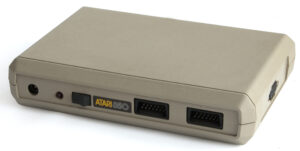
Front of unit (left-to-right):
- Power In jack
- On power indicator light
- Power Off / On switch
- Two I/O Connectors (Atari SIO)
Right side of unit:
- Parallel Interface port
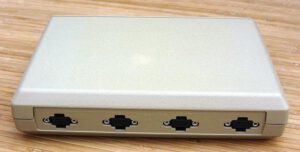
Rear of unit (left-to-right):
- Four Serial Interface ports, 4 - 3 - 2 - 1
850 internals:
- 6507 MPU (MOS Technology MCS6507 or equivalent), C010745
- 6532 PIA. Two of:
- MOS Technology 6532 RAM-I/O-Timer (RIOT) or equivalent, C010750
- 4KiB X 8 Bit ROM, C012099
Manuals:
- Atari 850 Interface Module Operator's Manual C015953 Rev. 1 1980
(preliminary version shipped with earlier/most 850 units; 102 pages)
- Atari 850 Interface Module Operator's Manual C017651 REV. B 1982 (15 pages)
- Atari 850 Interface Module Technical Manual C017652 REV. B 1982 (106 pages)
- Atari 850 Interface Module Field Service Manual
- CS 400/800-S004-B 4/81
- FD100036 April, 1981
Power: Used with an external 9 volt AC transformer power supply rated for at
least 17 watts: Atari CA014748 or equivalent.
The 850 was designed by R. Scott Scheiman at Atari,
The 850 was alo sold as bareboard with a parts list