On this page my experiences with an Apple 1 clone, my third! Build as kit, a nice experience and another 6502 system in the house.
I start with describing building the kit and getting it to work, last running some Apple 1 programs.
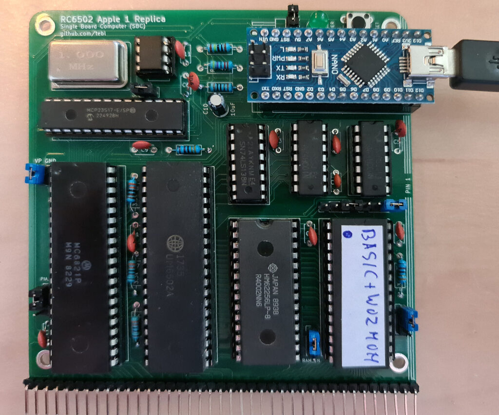
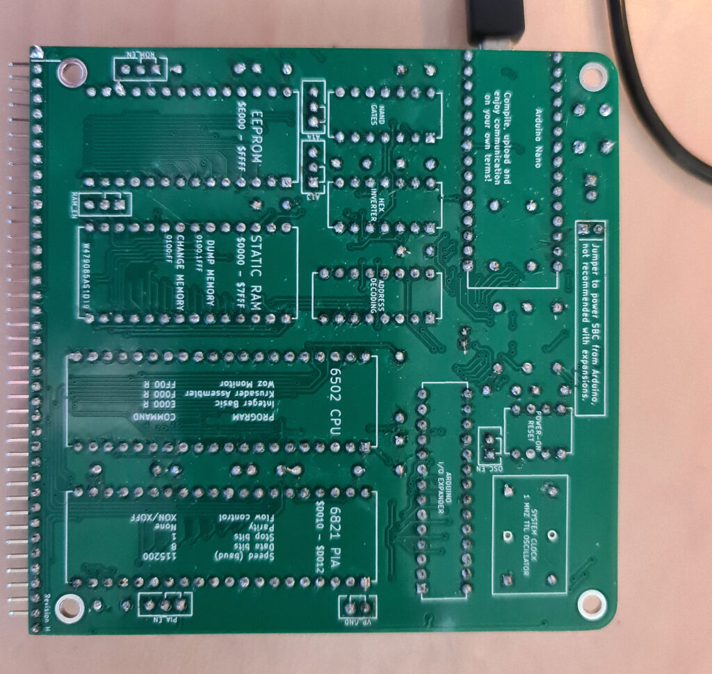
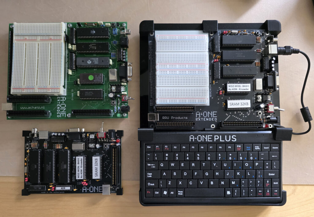
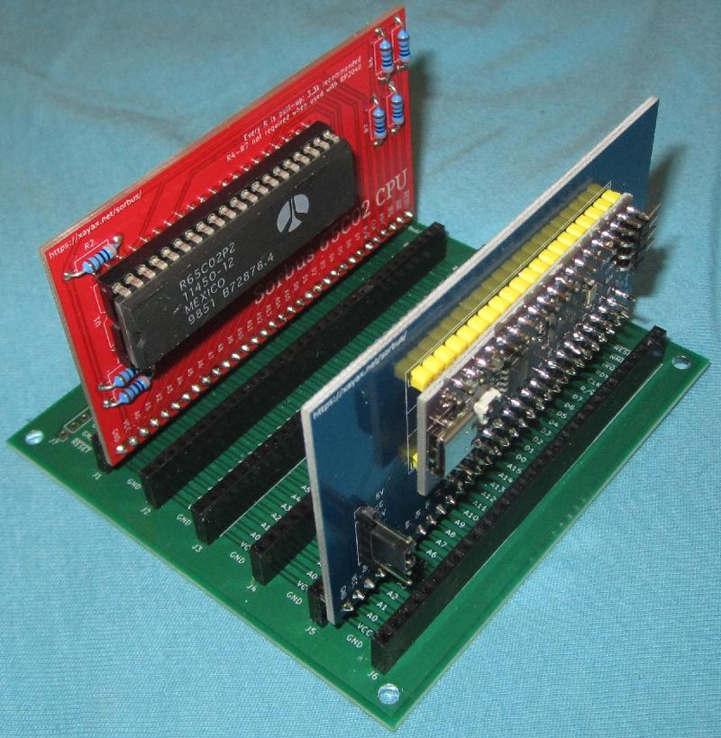
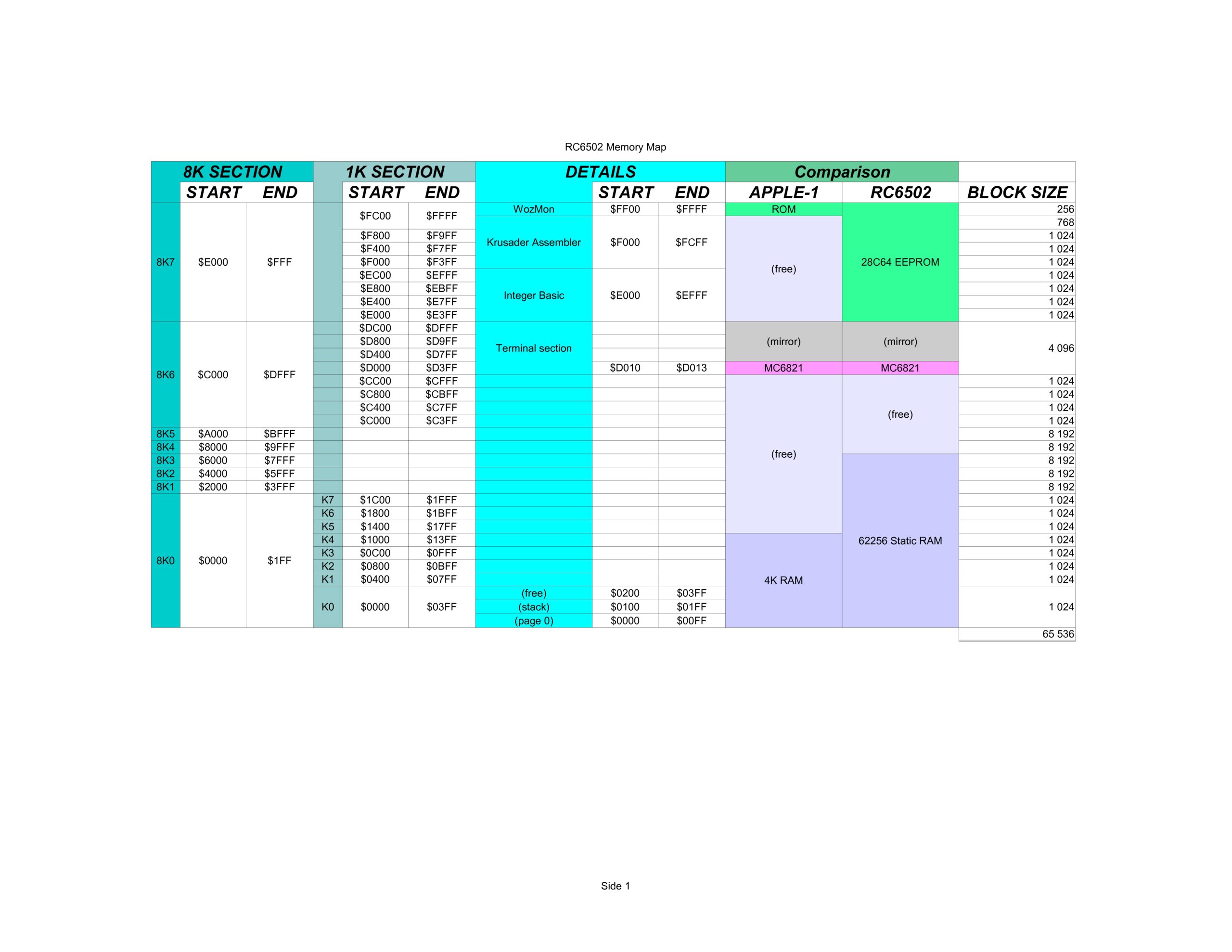
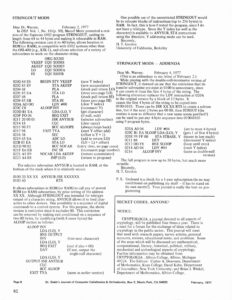
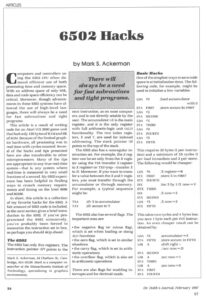
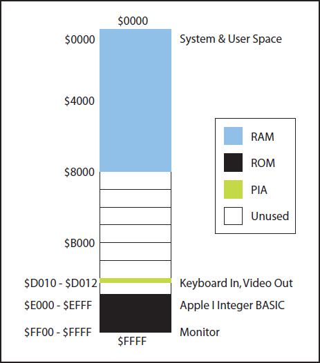
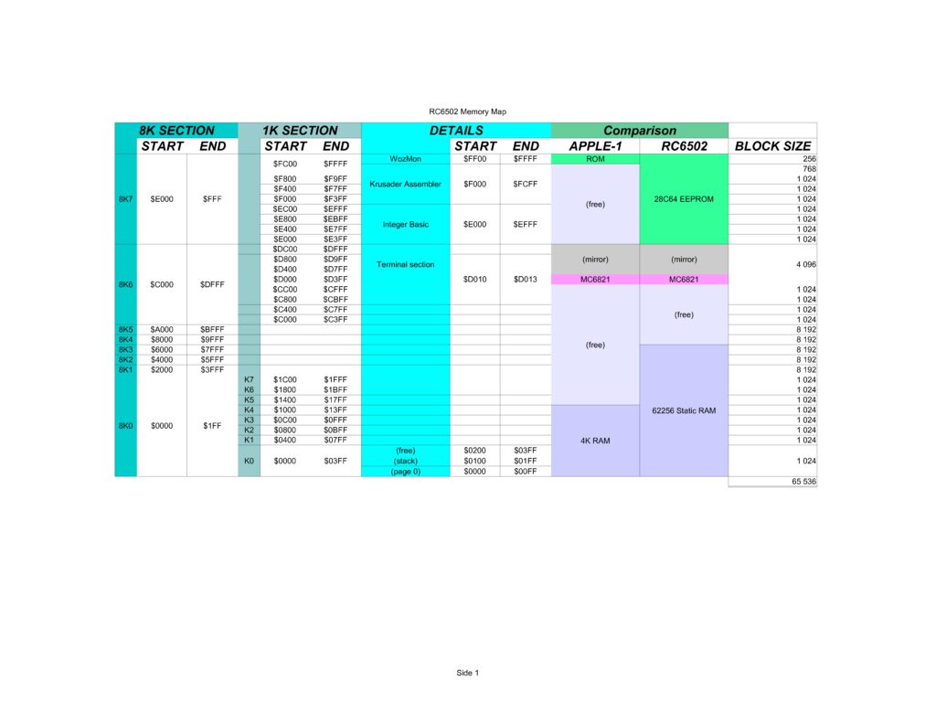
RC6502 Apple 1 SBC
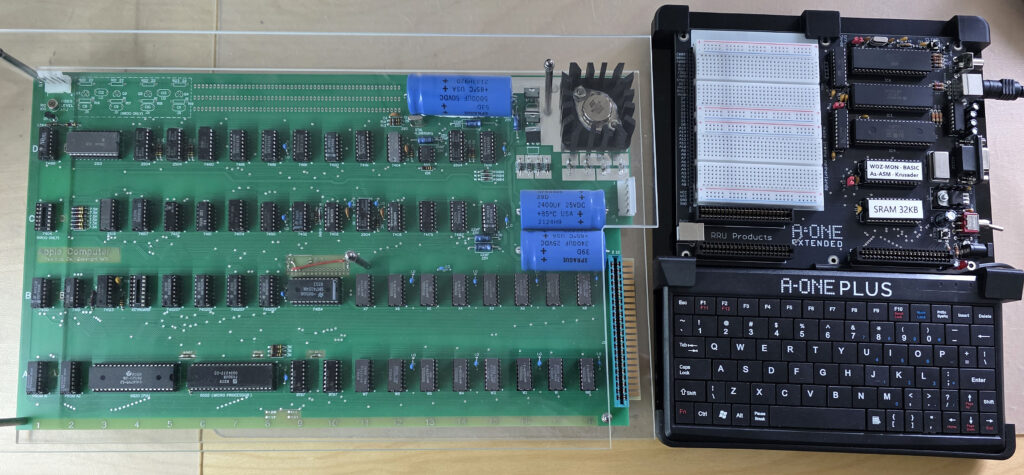
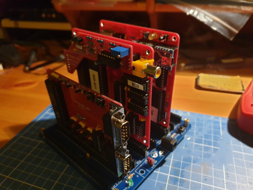
My third Apple 1 clone! A-One, Replica 1 are the other two. Same principle: the computer part is identical tot the Apple 1 (with modern RAM and ROM), the videopart is replaced with a processor, this time the Arduino Nano.
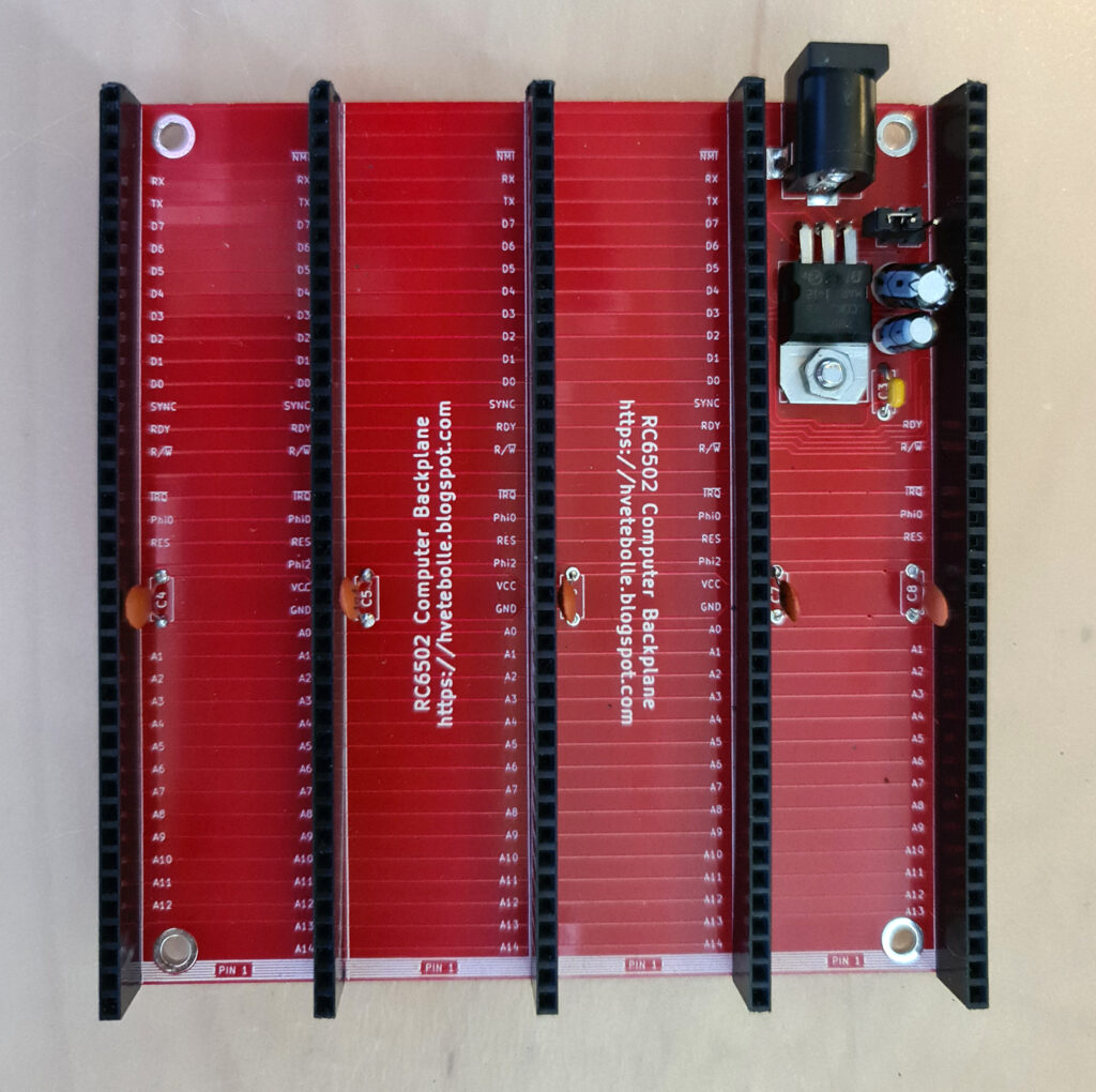
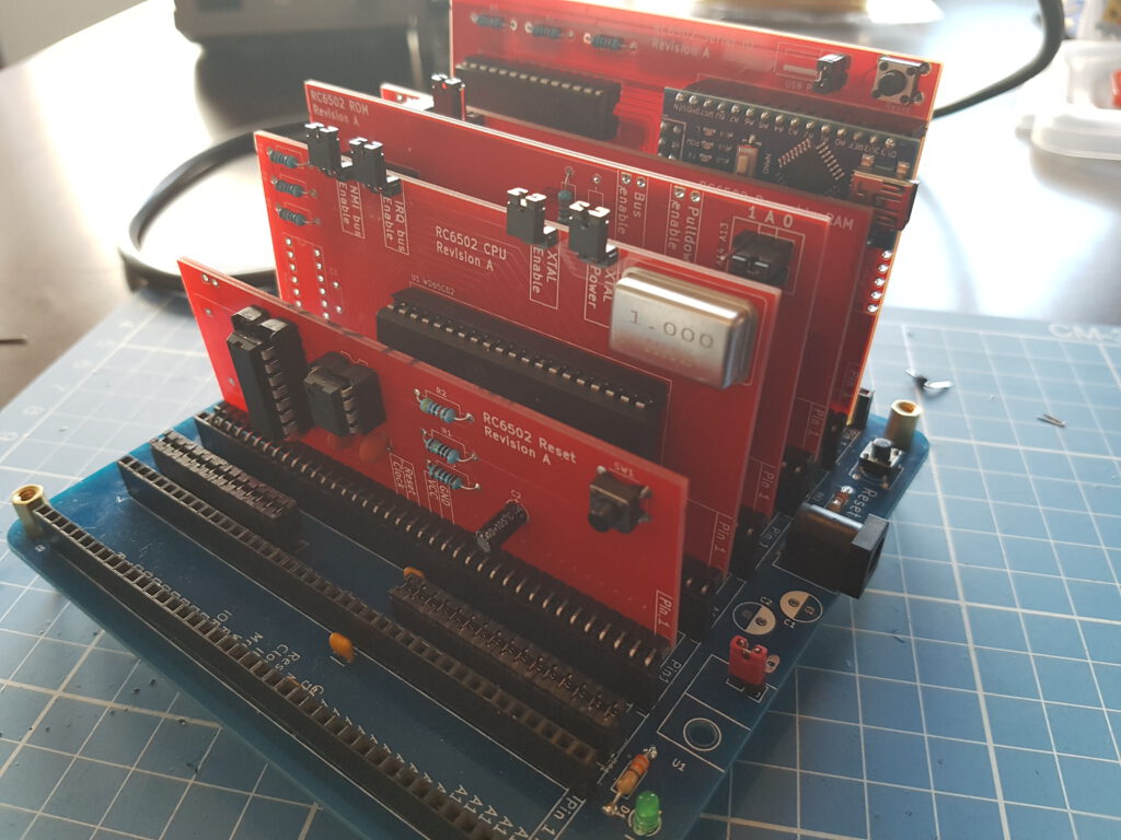
Quite a big system, a SBC or a bus based system. Lots of small cards like the RC2014, same busconnector.
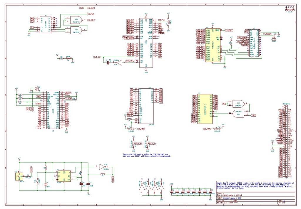
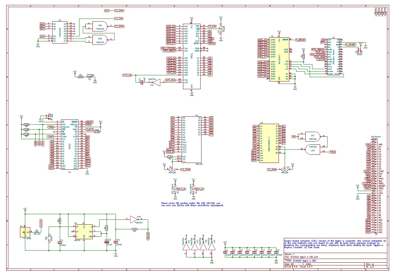
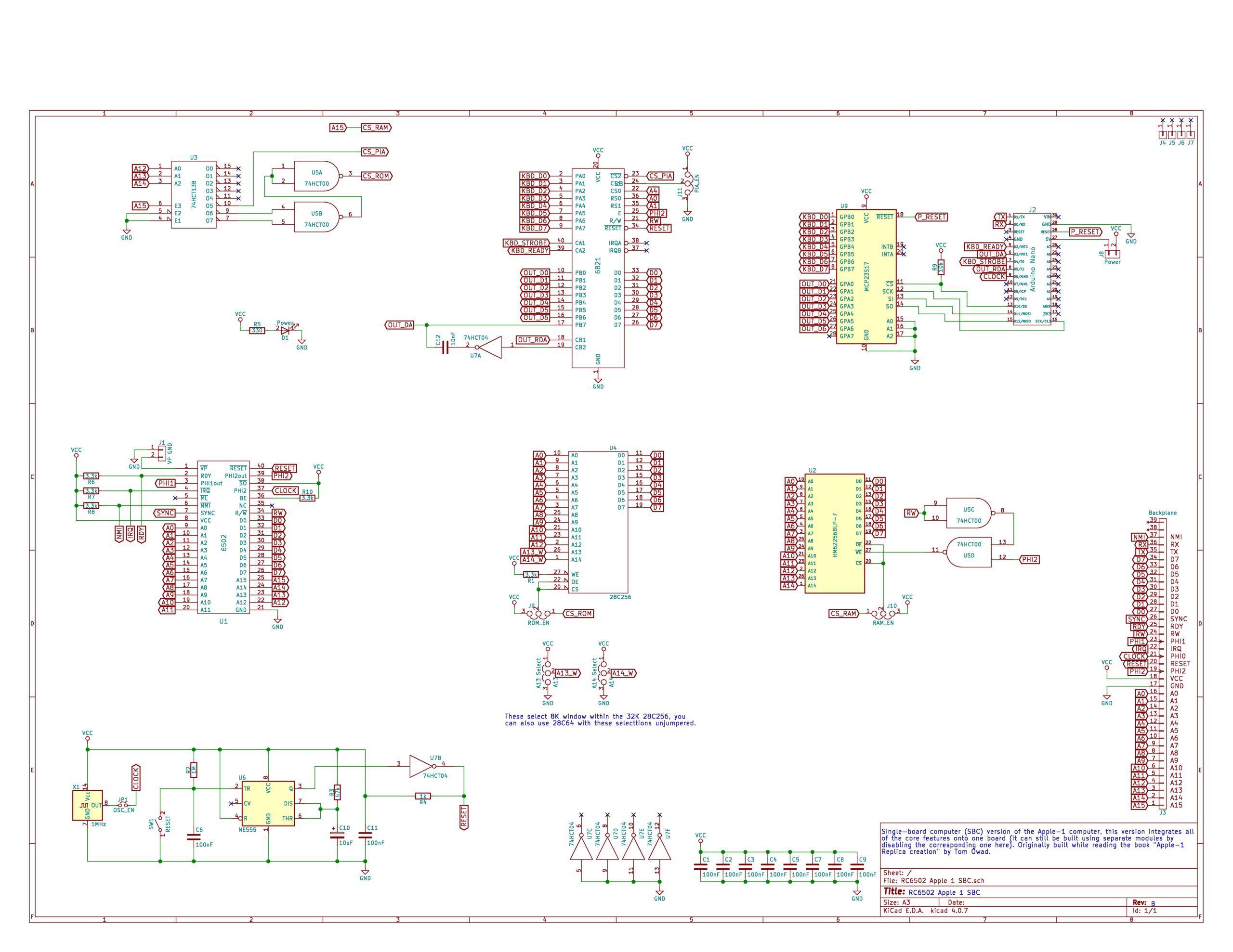
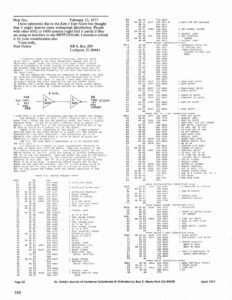
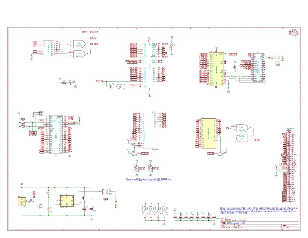
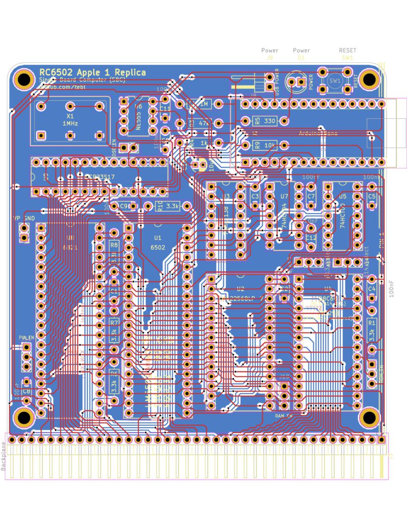
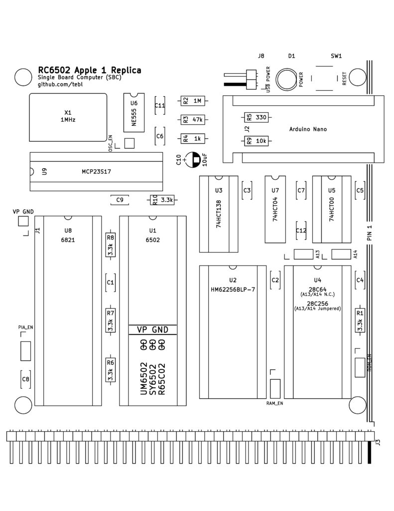
SBC schematic
Github archive here.
The RC6502 SBC shown here is a part of the RC6502 system. First it was a variant of the RC2014 design for the 6502 instead of the Z80: a simple backplane and small single purpose cards such as CPU, RAM/ROM etc. Cheap, easy to build and debug.
Blog here, archive on github here.
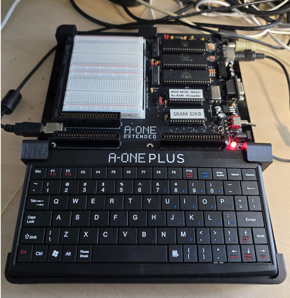
The last card developed is an SBC which can be used standalone, but also with the backplane enhanced with other cards in the RC6502 system.
I built this card with the backplane with the (long term) plan to develop my own 6502 bus based system.
I bought a kit from my Dutch retro friend Hein Pragt. He has a webshop with rare retro parts, such as required for the RC6502.
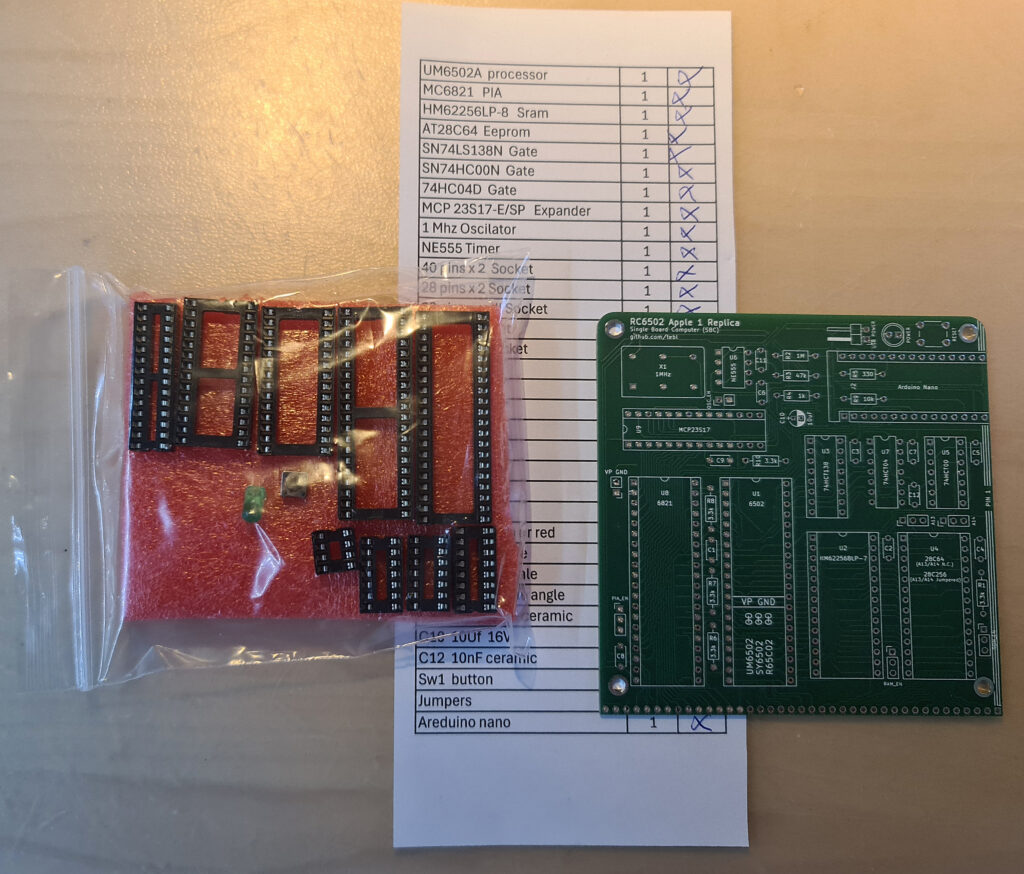
The kit has all you need, The EEPROM is already programmed.
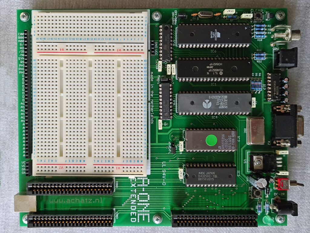
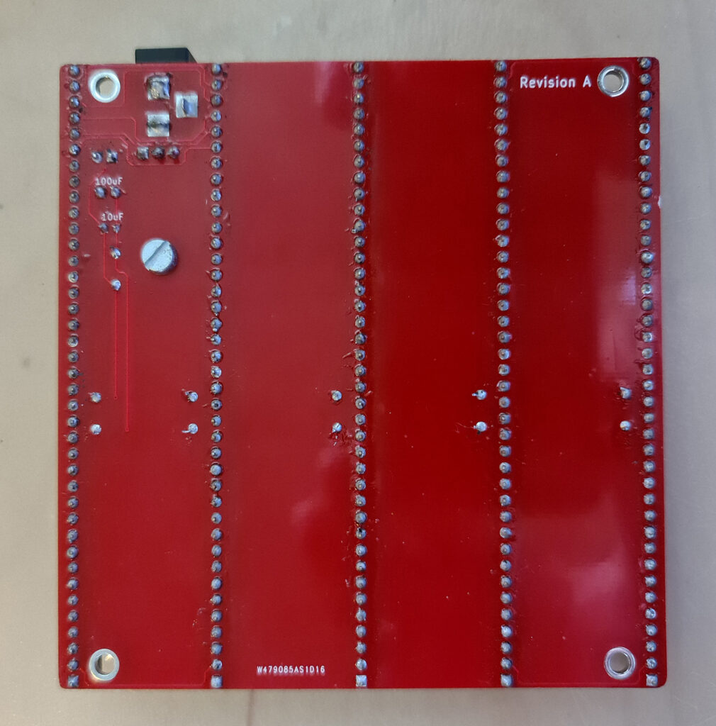
Quite a lot of solderpoints, the backplane is made up of 5 39 pin connectors, the SBC itself with IC sockets.
A good PCB and BOM and an excellent documented github website helps you to do a nice job to put it together.
You can see ath the photos above it has many jumpers to deactivate on board resources such as RAM or ROM. The correct setting is shown in the photo, the documentation describes the settings but lacks pictures.
Program the Arduino Nano
The Arduino Nano comes without the RC6502 sketch, But the source is available on the github.
I compiled the RC6502 sketch for the Nano with the Arduino IDE, instructions below for the Windows version 2.3.2. Any version since 1.8 will do afaik.
You need the sketch pia_communicator from the RC6502 github software and the Majenko MCP32S17 library.
I made a small change to the sketch (allow lowercase to be entered, so you must use CAPS Lock on your terminal emulator, to use it in 6502 code write your own Get Character routine, in map_to_ascii commented out)
- Unpack the archive and place pia_communicator.ino and MCP23S17 Majenko library in {Documents}/arduino and get at least
C:\Users\hanso\Documents\Arduino\libraries
C:\Users\hanso\Documents\Arduino\pia_communicator
C:\Users\hanso\Documents\Arduino\t.txt
C:\Users\hanso\Documents\Arduino\libraries\MCP23S17
C:\Users\hanso\Documents\Arduino\libraries\MCP23S17.cpp
C:\Users\hanso\Documents\Arduino\libraries\MCP23S17.h
C:\Users\hanso\Documents\Arduino\libraries\MCP23S17\src\MCP23S17.cpp
C:\Users\hanso\Documents\Arduino\libraries\MCP23S17\src\MCP23S17.h
C:\Users\hanso\Documents\Arduino\pia_communicator\pia_communicator.ino
- Start the IDE, open pia_communicator.ino
- Select Arduino Nano as board
- Connect the Arduino (may stay onboard the RC6502, leave the optional power of the motherboard off) and select the COM port
- Compile and upload to the Arduino Nano
- Save the sketch if changed and exit Arduino IDE
For your convenience: here my archive with the files mentioned above.
Run with Tera Term
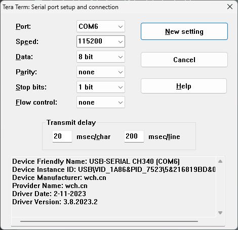
I use Tera Term on Windows and Minicom on Linux to talk to SBC’s like the RC6502.
The RC6502 (the Arduino Nano) uses serial communication, the Nano appears as COM/TYY port. 115200 baud, 8 bit, one stop bit. no parity.
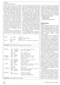
To upload programs (in ‘woz’ format) one needs to give the slow 6502 some time to deal with the incoming data.
That is done with character and line delay. What works for me is shown in the next figure.
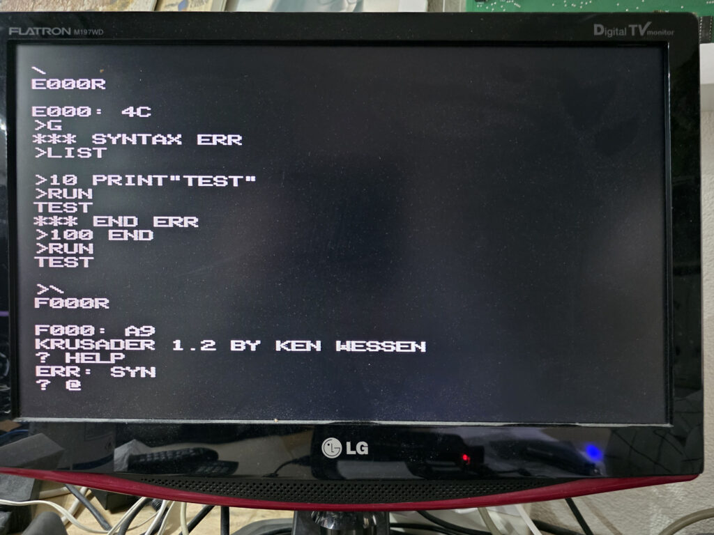
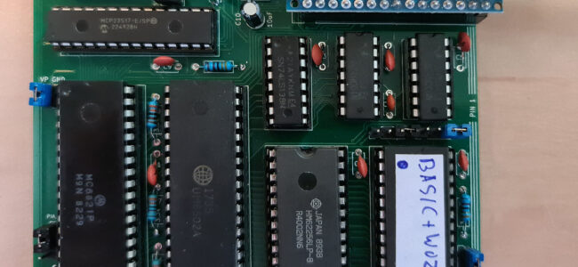
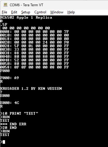
First run: WOZ monitor, Apple 1 Basic, Ken Wessen’s Krusader as present in the EEPROM.
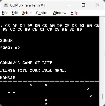
Conway’s Life
A small program to test the RC6502. Contributed by Hein Pragt in the examples of his Apple 1 Emulator
Needs to set the Retro Term to 40×24 screen!

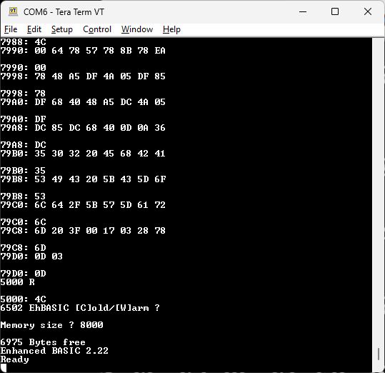
EHBASIC
To give the board a good test I selected a large program, a descendent of Microsoft 6502 Basic: EHBASIC by Lee Davison.
Chris Hill played around with Jeff Tranters EhBasic source for the Replica 1 and got it to load on the RC6502, He generated a woz file to load it over the serial terminal.
It takes some time to load with the required delays in character and line routines (see Tera Term section) but it works!

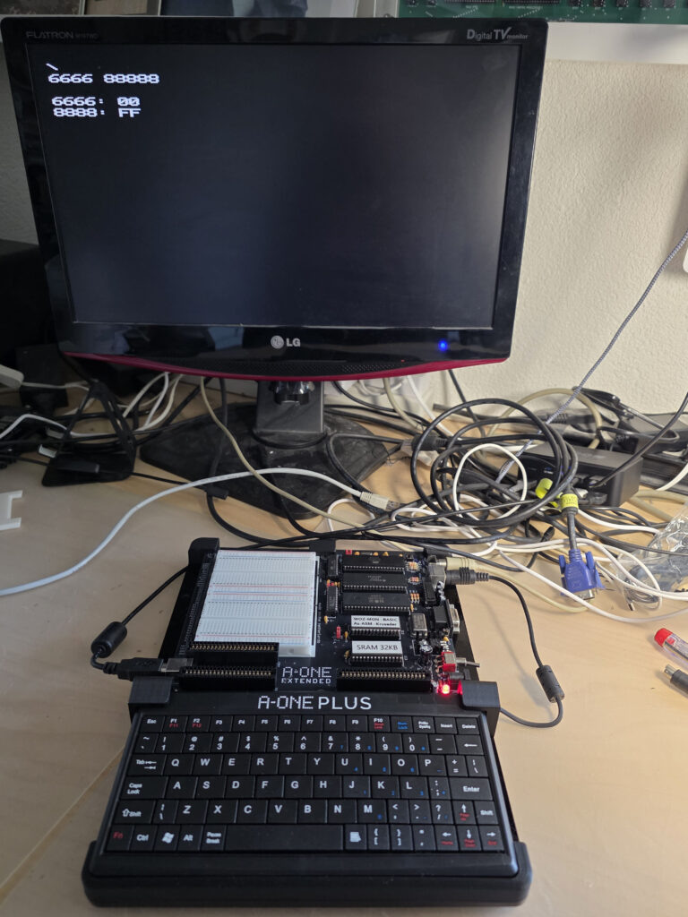
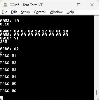
Memory test
A memory test from here, archive with code and source here.
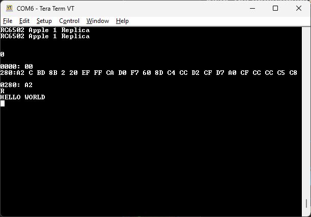
Hello World
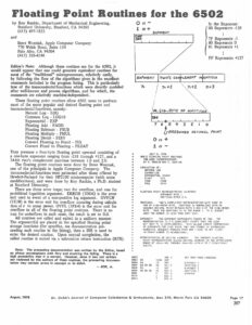
280:A2 C BD 8B 2 20 EF FF CA D0 F7 60 8D C4 CC D2 CF D7 A0 CF CC CC C5 C8