
On this page:
- What is a Jolt
- History of the Jolt
- Jolt images
- Early Jolt with a 74154 decoder
- Jolt Software
- Jolt extension cards
- Documents
- Replica by Scott LaLombard
- Jolt replica by Eduardo Casino
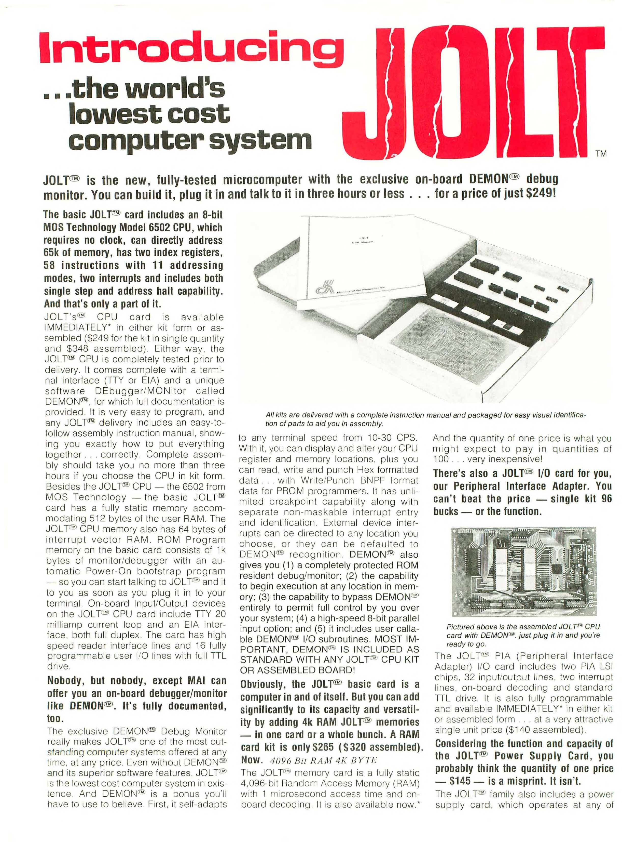
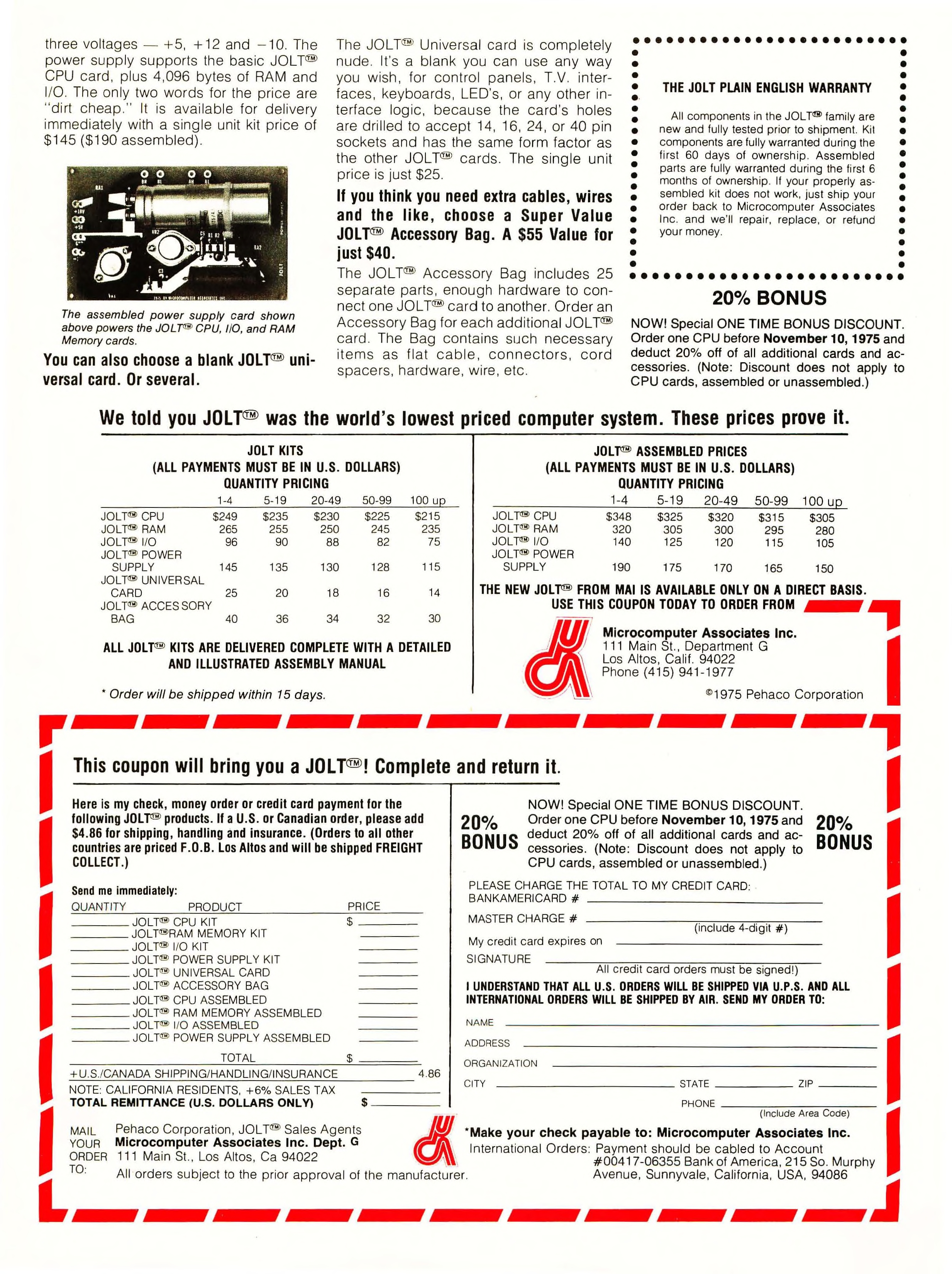
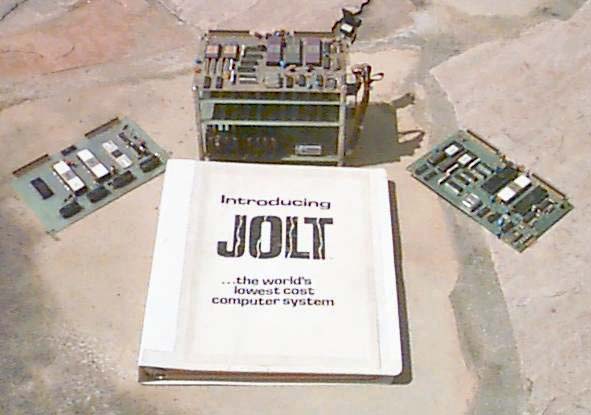 Jolt was the first 6502 singleboard computer. On December 1975, the coveted inside-front-cover of Byte magazine contained a two-page advertisement for “the world’s lowest cost computer system”. This was perhaps the first non-MOS Technology 6502 based computer system to come to market, The computer was named Jolt, and it was marketed by Microcomputer Associates Inc. (MAI) as both a kit for $249, or fully assembled and tested for $348 (Dec. 1975 Byte). Microcomputer Associates also sold add-ons for the basic system. They included 4 kilobytes for $265, an I/O card for $96, and a power supply for $145. Either at that time or shortly later MAI expanded the line to a RAM card and an EPROM card using 2702 PROMS. The boards were about 4″x6″ arranged in a vertical stack jointed by a ribbon cable. Only 5 volt power was needed. Software available in PROM was RAP (Resident Assembler Program) and Tiny Basic from Tom Pittman.
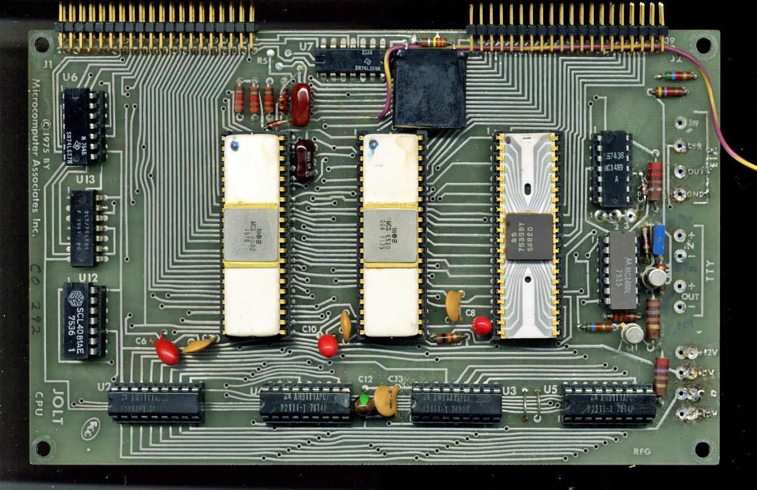
 As can be seen in the photos of the Jolt front, back and experimenters card below, the system is quite simple. In fact it is a TIM system (the 6530-004 is the middle IC), with a 6502 at the right and a 6820 PIA on the right. Some glue logic on the right and the top, RAM on the bottom (4x 2111 for 512 byte memory) and RS232 TTY interface at the right (1488, 1489 line drivers). The system clock was a RC at 750 KHz, in the photo the clock is a 1 MHz crystal added later.
The TIM IC, 6530-004,contains the ROM (1K), timers, 128 byte RAM, 16 I/O) and 64 bytes RAM. The PIA 6820 adds another 16 bit I/O.
JOLT SPECIFICATIONS SUMMARY
(See the Microcomputer Associates Catalog in PDF format here)
• MOS Technology 6502 CPU
• MOS Technology 6530 with DEbug MONitor (a 6530-004 TIM)
• 750 KHz clock operation-RC controlled or crystal controlled with user supplied crystal.
• 512 bytes RAM
• 64 bytes RAM-located at interrupt vector locations
• Expandable address data lines
• Direct drive to 8 K bytes of memory
• 26 Programmable I/O lines
• Two hardware interrupts
• Serial interface for 20 ma current loop and EIA RS232C
• 4.25″ x 7″ printed circuit card
• Compatible with other JOLT cards
Documents
|
Jolt Replica User manual |
|
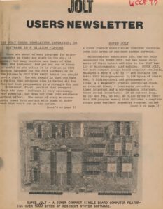
Jolt User Newsletter |
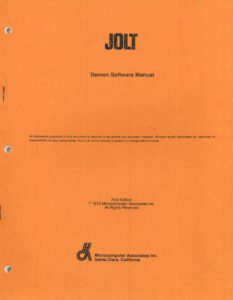 |
DEMON software manual (this manual has an alternative listing of the TIM 6530-004 monitor) |
JOLT SYSTEM DESCRIPTION
The JOLT system consists of a set of modular microcomputer boards which can be used singly or tied together to produce any desired microcomputer system configuration. The minimum system is one CPU board. which alone constitutes a viable computer system complete with central processor. 1/0. interrupts. timer. read/write memory. and a complete software debug monitor in read-only memory. Additional boards in the JOLT system include a 4 K byte RAM , 1/0. Power Supply and blank Universal Interface board. A large JOLT system could have up to 32 K bytes of RAM memory. up to 128 lines of bidirectional 110 and 16 interrupts. JOLT boards come in kit form or assembled. and are ready to use in any form. from home hobby kits to industrial applications. All JOLT components are new. fully tested and fully warranted by MAI.
CPU
The internal oscillator operates in a “free run” mode with a capacitor and variable resistor supplied on the CPU printed circuit board. The frequency of oscillation may be adjusted with the variable resistor. If a very stable clock is required by the system a crystal may be added to the CPU board.
The RESET input to the CPU is pulled to logic ground by an RC circuit (t=33 milliseconds) on the printed circuit board. The CPU normally fetches a new program count vector from hex locations FFFC and FFFD upon activation of the RESET line, but these locations are in the interrupt vector RAM and therefore volatile. Hardware on the CPU board causes the CPU to begin executing the monitor program by forcing the effective sixteenth bit of the address bus to a logic ZERO during reset. As a result, the RESET function on the JOLT CPU card causes the debug monitor (DEMON) to begin executing.
There are two interrupt inputs to the CPU. One interrupt is maskable under program control (IRQ) and the other (NMI) is not.
A READY control line provides for asynchronous operation with slow memory or I/O devices.
The address bus (A0-A15). the data bus (00-07). the two phase clock (PHI). the reset line (RESET). the interrupt lines (IRQ and NMI). and the ready line (RDY) are all available at the edge connector of the CPU board. The loading restrictions should be considered when using the signal lines driven by the CPU for external system expansion.
Program RAM
There are 512 bytes of program RAM provided on the CPU card. The program RAM is hardwired addressed as the first 512 bytes of the CPU’s 64 K of memory address space. It may become necessary to remove these RAM’s from their sockets if a 4 K memory card is also hardwired in this address space. The program RAM on the CPU card uses NMOS RAM chips type 2111, 512×4 bytes.
Monitor ROM and Interrupt Vector RAM
The monitor ROM is located in the last 1 K bytes of the lower half of memory space (first 32 K bytes). The interrupt vector RAM is located in the last 64 bytes of the 64 K memory address space. The monitor ROM and the interrupt vector RAM as well as additional I/0 are implemented with a single 6530 chip, the 6530-004 TIM
Programmable User I/0
The programmable I/0 lines available from the CPU card are provided by a Peripheral Interface Adapter (PIA) and a 6530 ROM chip. The PIA has two 8-bit 1/0 ports with two interrupt-causing control lines each. Two jumpers are provided on the card which connects one or both PIA interrupt outputs to the CPU IRQ interrupt line. Refer to the CPU assembly drawing for proper identification of the jumpers. A Data Direction Register for each port determines whether each 1/0 line is an input or an output. The 6530 ROM chip provides 10 additional I/O lines that may also be specified as input or output lines under program control. There are eight 1/0 lines from one port on the 6530 and two 1/0 lines from the second port. These I/0 lines may be used in conjunction with DEMON for interfacing a high speed paper tape reader to the CPU card. In the paper tape reader application, the eight 1/0 lines from one port are used as inputs and two I/0 lines from the second port are used to accomplish the handshake control between the reader and the CPU card.
The PIA is hardwired addressed as location 4000 to 4003 in the memory address space. Memory addresses from 4000 to 4003 are allocated for PIA devices so that the JOLT system may be easily expanded to accommodate up to eight PIA chips. The 6530 uses addresses from 6200 to 6E07 for eight I/0 functions. The unused memory addresses occur because address bits A10 and A11 are ignored to simplify address decoding. The 6530 I/0 lines may be referred to as Monitor I/0 because these lines are commonly used for a high speed paper tape interface.
See the TIM page for more information on timers and I/O.
Standard Interface Circuits
The JOLT CPU card provides direct interfacing with a 20 mA current loop and RS232C terminal. The 20 mA current loop requires +5 v and -10 v whereas the RS232C interface requires +12 v and -10 v. Both interfaces are wired in parallel on the input and output thereby allowing both interfaces to be used simultaneously.
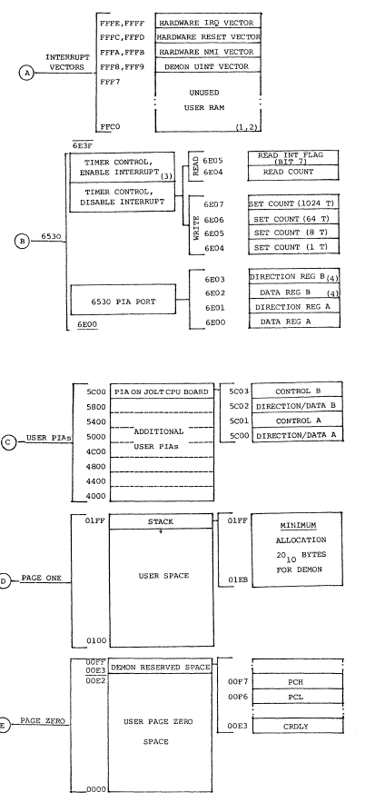
JOLT SYSTEM MEMORY MAP
The memory map on the following charts explains what functions have been assigned to each segment of the JOLT address space. It is recommended that users respect this space allocation when adding memory and peripherals to their JOLT systems. Space has been reserved for 32 K bytes of user RAM or ROM, seven additional PIA devices, and up to 512 user I/O device registers. Other areas are reserved for JOLT expansion, new JOLT peripherals and memory options will use these spaces. Users are advised to not use JOLT expansion space unless absolutely necessary. Note that some areas used by the JOLT CPU board and PIA boards have more space indicated than there are registers or locations in the device occupying them. This is because these devices do not decode all address bits, or use some of the address bits for special functions. For example, the 6530 timer determines the time scale and interrupt enable/disable by the address used to access it. Thus, these “partly filled” areas are actually entirely used and are not available for other uses.
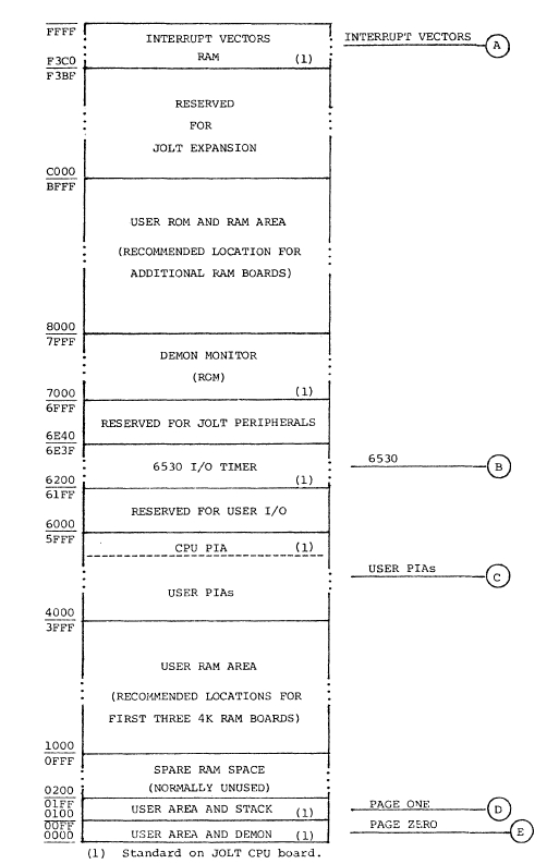
(1) Standard on JOLT CPU board.
(2) Available to user-not used by DEMON.
(3) To get enable-interrupt address, add 0008 to disable-interrupt address with corresponding functions.
(4) Reserved for DEMON use, TTY control and reset functions
History of Jolt Serial One, Bill Ragsdale (from http://www.old-computers.com/)
Jolt was designed and developed by Raymond M. Holt, Founder and Executive Vice-President of Microcomputer Associates. Holt went on to design the SYM-1 single-board computer, a KIM-1 clone. In the late 1990’s Holt was finally given government permission to discuss his role in the development of the F-14 Tomcat. Holt claims he designed and developed the worlds first microprocessor one year before Intel.
Manny Lemas was the co-founder of Microcomputer Associates, Inc. Ray Holt was the hardware side and he was the software side of the business. He wrote the DEMON (Debugger/Monitor) software for the JOLT.
This software was actually developed for MOS Technology for use in the TIM chip and the KIM-1 single board computer. M.A. was granted rights to its own version of the software for use in the JOLT, they used the TIM 6530-004 IC!
I bought the first Jolt microcomputer out the door. I saw its advertisement (in Byte?) and was just starting a project in security access control. We were doing a crash project to demonstrate reading magnetic striped ID badges for Honeywell. We needed to accept a real-time bit sequence, extract numeric data and do a simple name vs. number lookup. An ideal job for a small processor. But remember, this was 1976. Development systems cost $5,000+ and none were offered for the 6502. (Later, MOS Technology offered one and Rockwell had a very good one.)
I ordered a Jolt system on a Wednesday or Thursday and was told Microcomputer Associates Inc. (Manny Lemas and Ray Holt) was awaiting the first silicon of their DeMon monitor to come by air from MOS Technology in two days, on Saturday. DeMon was a one chip Debug-Monitor containing 1K of ROM, 512 bytes of RAM, paralled IO, an ASCII serial interface and a monitor program. With the 6502 processor and a simple clock you could have a two-chip microcomputer. DeMon was later renamed Tim, Terminal Input Monitor.
MAI received their first DeMon chips about 9 AM Saturday morning, plugged in one, it ran, and I picked up the first unit at noon at their office. IIRC the Jolt had an inked-in serial number 0 or 1. Over the week-end I built a teletype interface as Jolt had a voltage output while the Teletype had current loop.
The Jolt is somewhat famous for the part it played in the development of the prototype Atari 2600 VCS, which was assembled using the Jolt computer board.
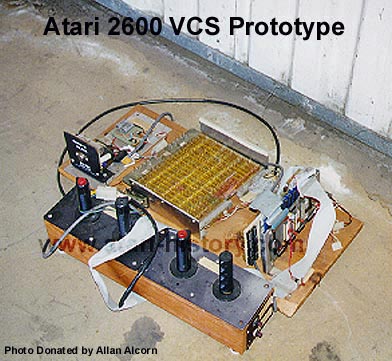 This photo is one of the original wirewrapped prototypes for “The Worlds Most Popular Video Game” aka… The Atari Video Computer System (VCS) Model #2600. The interesting and eye catching part of the unit besides the extremely intricate hand wired area (TIA perhaps?) are the controllers, you look and say “Hey those don’t look like the standard CX-40 joysticks I’ve come to know and love all these many years!” The controllers are actually from the Atari/KeeGames TANK coin-op arcade game. The actual Atari VCS joysticks would later come from a home console game of TANK which was sold under the Sears exclusive brand label. The Atari Tank joysticks for a one player would act as left and right treads on the home tank game and then they popped out of the rectangular home console and could be used for two player action and would allow each user to use one joystick just like Atari VCS Combat (CX-2601).
The above prototype designed by Ron Milner and Steve Mayer in Grass Valley, Ca. at Cyan Engineering (a company owned by Atari, Inc.)is actually a combination of many parts. The wirewrap board was the original version of the STELLA chip. The boards to the right are a memory board and a “Jolt” 6502 board ) and on the far left is a 5V power supply. The above Stella prototype had actually been thrown out in the garbage at Atari at one point. Owen Rubin, one of Atari’s first programmers had found it in the trash and recovered this piece of history and placed it into the safe hands of Atari’s Employee #3, who built the first Atari Pong, Allan Alcorn.