On this page:
– SS-50 6800 CPU Power-On Reset
– SS050 FAQs
– SS-50 and SS-30 standards
SS-50 6800 CPU Power-On Reset
Update (2/7/2021): Rather than using a 220uf electrolytic, use a 47 uf tantalum capacitor instead.
Update (2/5/2021): A previous version of this page said to add the capacitor to U1… that was incorrect! It is definitely on U4, the MC6875!
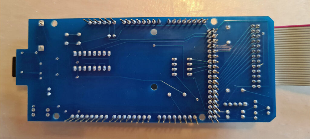
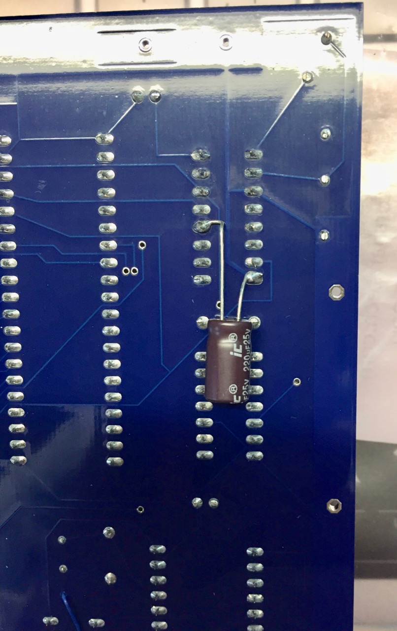
All existing versions, including up to 3A, of the SS-50 6800 CPU Board have a problem where power-on reset does not work. A part is missing. This is not a severe problem, as the user can press the RESET button on the board or the motherboard to do the reset, but it can be easily fixed.
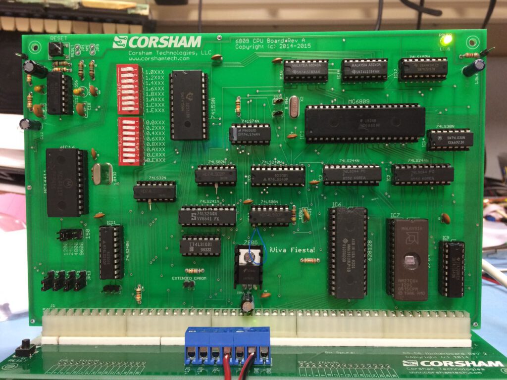
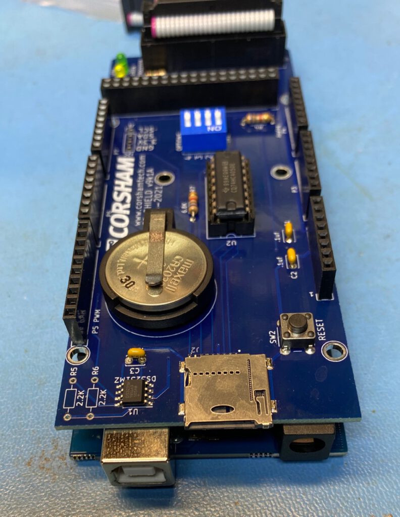
You’ll need to solder a 47 uf, 16v (or higher) tantalum capacitor to the back of the board. The negative side of the capacitor goes to U4 pin 8 (ground) and the positive side goes to U4 pin 12. This is a picture from when I was using a much larger electrolytic capacitor, but I’ve switched to a 47 uf tantalum cap for all new boards:
All future revisions of the board will include this fix.
SS-50 FAQs
Q: Where can I get a copy of the SS-50 standard?
A: There is no standard, just a loose specification manufacturers followed when designing boards. The first SS-50 machine was from SWTPC and had a 6800 processor, so the buss was closely designed around that processor’s architecture. When SWTPC added a 6809 board they more-or-less followed the previous use of most pins on the buss, but also changed the purpose of others. Other companies began making compatible boards based on what was already on the market. To paraphrase Dr. McCoy of Star Trek fame, “Dammit Jim, I’m a buss, not a standard!”
Q: I keep hearing SS-50 and SS-30. Are they the same thing?
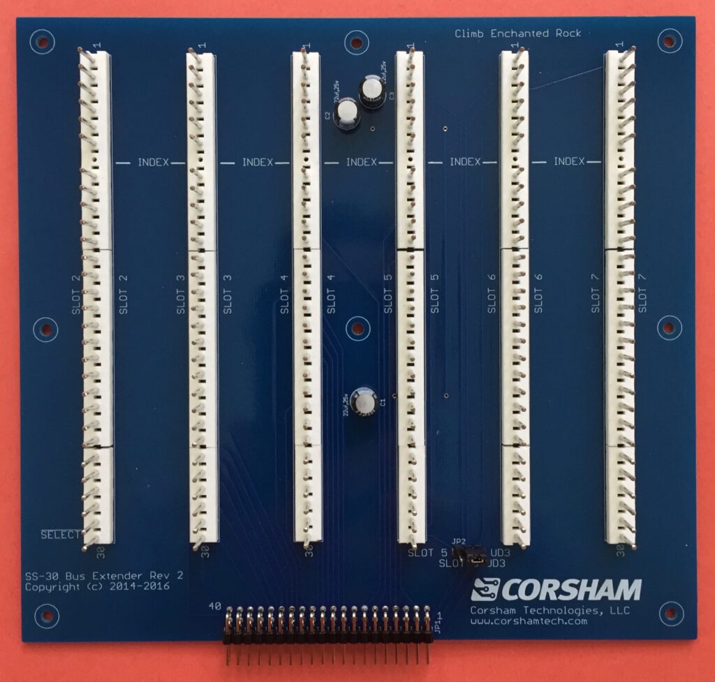
A: No, but closely related. The SS-50 buss is the main processor buss which includes all the address, data, and control signals needed to control the buss or respond to the processor board. It has 50 pins. The SS-30 buss is meant only for I/O. Decoding addresses takes a few chips that chew up real estate on a peripheral board and add cost, so SWTPC does the decoding on the motherboard and runs only essential signals to the peripheral boards. This is the SS-30 buss, and has 30 pins. Only a few address lines, data lines, and very few control signals.
Q: What are those strange connectors?
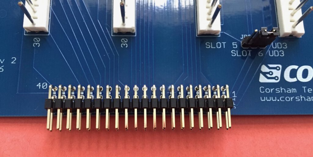
A: Those are Molex connectors which SWTPC used on other, non-computer, products. Hey, use what you’ve got in stock to save development time and stocking cost! They are still available from many sources, but the cost has gone up tremendously since they aren’t widely used anymore. The male connector with 10 pins, as used on motherboards is AMP/ TE Connectivity part number 1-640384-0, while the female connector used on plug-in boards is Molex/Waldom 09-48-2101. There is also a polarizing plug that goes into the female connectors and is Molex part number XXXXXXX.
Q: Which pin is pin 1 on both the SS-30 and SS-50 busses?
A: Technically, there were no pin numbers. SWTPC simply used the name of the line and never referenced a pin number. Many companies use http://www.cs.unc.edu/~yakowenk/swtpc/ss50.html as a guide, but I am aware of at least one board where the pin numbers were exactly the opposite direction.
Q: Boards don’t seem to plug in without a lot of force. Are you sure they are meant to plug into the motherboard?
A: Yes, the Molex connectors offer a lot of resistance at first but eventually get looser with insertions and removals. Make sure the polarizing plug is aligned properly with the missing pin on the motherboard. Some people insert a small screwdriver or used dental tool into each of the female connectors to loosen them up, but be very careful not to over-loosen them or else some of the pins might not make contact.
Q: Why are there so many pieces to build a complete system?
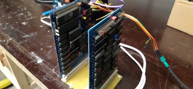
A: This is a clone, so it has an SS-50 buss for the CPU and memory, and an SS-30 buss for the peripheral devices. The original systems had a motherboard, CPU board, memory board(s), serial console board, terminal, etc, which means our system does too. Back in the day, people were driven by cost (just like now) so systems were modular, allowing someone to buy exactly what they wanted (or could afford) while building their system.
Q: What is the bare minimum to get started?
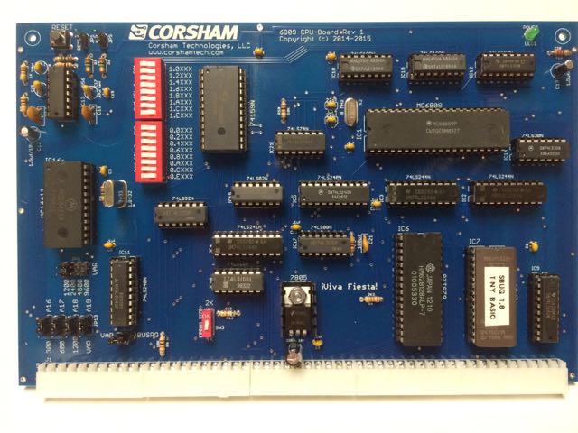
A: The motherboard contains the framework for the other boards to plug into, and is required. To use a terminal for a console, a serial board is required. We have two CPU boards, one having a 6800 and 16K of RAM, and a 6809 CPU with 128K. Only one CPU board is required.
Q: What can the bare minimum systems do?
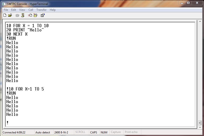
A: Actually quite a lot, thanks to all the available software on the net. If you want to re-live the early days of the microcomputer revolution, there is plenty of RAM on either CPU board to load up Tiny BASICs, play games, write assembly language code, etc.
Q: How about mass storage?
A: We use our SD Card System. Our CPU boards include the low-level code providing drivers for the SD system, along with monitor commands to boot an operating system.
Q: What OS do you provide?
A: For the 6800, we use FLEX. For the 6809 we use FLEX/9 but have talked to various groups about multi-tasking operating systems. A different (still not released) I/O board is being developed to add additional capabilities for some OSes.
Q: An OS is great, but is there any software for those old systems?
A: Absolutely! Try looking at the FLEX User Group site: www.flexusergroup.com. They also have a large FTP site with a bunch of disk images. Drop those DSK files onto the SD card, mount the file as a disk drive, and you’ve got the disk contents for your use.
Q: So what do you guys do with YOUR systems?
A: I’ve got both 6800 and 6809 systems on the bench, both of which run FLEX, and are both a lot of fun to just program. I enjoy assembly language programming, so I’ve been working on some better tools for writing code.
Q: This stuff is all old technology, so shouldn’t it be cheap?
A: Sorry, this has a long answer. Some vintage parts are getting harder to find, demanding higher prices, or available in small quantities which have higher shipping costs. Some of these parts haven’t been manufactured since the early 1980s. Another big cost factor is that a lot of parts are needed, so while a more modern part might cost a few dollars more, the “more vintage” design sometimes requires several dozen of the older technology devices. Yet another factor is that the cost of printed circuit boards is based on the size of the board and the number being ordered. Ordering a single board might have a $70 set-up fee, and then $50 for the single board. Bumping up to 30 boards still has the $70 set-up fee, but the per-board cost might drop to $10. Given the size of the boards and the fact that each board has only limited functionality (as per the original design), the fixed prices are fairly high. This is a slightly political issue, but keep in mind the 25% US tax (it’s a tax paid by every American) on goods purchased from China, which is where a large percentage of electronic parts come from. Invoices from major US based suppliers show the dollar amount I had to pay in “tariffs” (it’s a tax) for that order.
Q: What else is needed, really?
A: Just a terminal and an RS-232 cable OR a personal computer with a serial port, cable, and a terminal emulator program. At shows we always use Wyse 30 terminals as they are available nicely refurbished for about $200.
Q: If I buy one, how hard is it to get running?
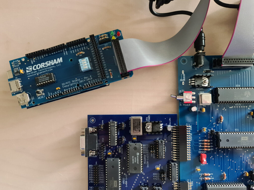
A: Before we ship a complete system, everything is plugged in, the system is brought up, then it is disassembled, packaged, and shipped. It’s really quite simple to plug in the boards and get running. Our suggestion is to set up just the motherboard, power supply, CPU board and serial board. Once your terminal is talking to the system, then it’s easy to plug in the parallel card, connect the SD card system, and boot into FLEX.
Q: Can I use Corsham Tech boards in a real SWTPC system or use SWTPC boards in a Corsham Tech system?
A: Absolutely! I sometimes bring several real SWTPC boards to demos, but they tend to draw a lot of current. Their 8K RAM board draws more than our complete 6809 system with a meg of RAM.
Q: Is there a case to put a system in?
A: No. It is expensive to have a case built unless we buy in very large numbers which we will probably never sell most of.
SS-50 Specification
This isn’t really any definitive definition of the SS-50 bus, as boards were simply produced that worked with other SS-50 boards. When SWTPC devised the bus, they just made things work and other manufacturers made compatible boards. Years ago I found two sites that gave a clear description of the pins for both the SS-50 and SS-50C versions, and since they haven’t been touched in decades, I decided to copy the information here just in case the original pages ever go away.
The SS-50 bus
The SS-50 was the main backplane in 6800 based SWTPC machines, and connected the CPU board with memory, disk controllers, and so on. As was common in that era, a board usually did just one thing, and did it well, so a system would have a CPU board, one or more memory boards, a serial board connecting to a terminal, and either a cassette I/O or disk controller board for program/data storage. Physically, the SS-50 bus consisted of rows of male Molex connectors, spaced 0.156 inches apart. The boards that plugged into it had the corresponding female connectors along one edge, rather than the more modern (and cheaper) printed-circuit contacts. The SS-50 bus had all signals from the processor. For I/O, see the section below about the SS-30 bus.
All signals starting with “/” are active low.
- /D0 – (complement) data bus line 0
- /D1 “
- /D2 “
- /D3 “
- /D4 “
- /D5 “
- /D6 “
- /D7 – (complement) data bus line 7
- A15 – address bus line 15
- A14 “
- A13 “
- A12 “
- A11 “
- A10 “
- A9 “
- A8 “
- A7 “
- A6 “
- A5 “
- A4 “
- A3 “
- A2 “
- A1 “
- A0 – address bus line 0
- GND – ground
- GND – ground
- GND – ground
- +8V – power line
- +8V – power line
- +8V – power line
- -12V – power line
- +12V – power line
- INDEX – no pin – prevents backwards insertion
- /M.RST – (complement) manual reset
- /NMI – (complement) non-maskable interrupt
- /IRQ – (complement) interrupt request
- UD – user-defined
- UD – user-defined
- /Phase 2 – (complement) processor clock 2
- /VMA – (complement) Valid Memory Address
- R/W – Read / (complement) Write
- /RESET – (complement) Reset or power-up
- BA – Bus Available for DMA
- /Phase 1 – (complement) processor clock 1
- /Halt – (complement) halts the processor
- 110b – 110 baud clock signal
- 150b – 150 baud clock signal
- 300b – 300 baud clock signal
- 600b – 600 baud clock signal
- 1200b – 1200 baud clock signal
The SS-30 Bus
I/O was handled on a distinct 30-pin bus (the SS-30), which was generally similar to the SS-50 but had a “board select” signal instead of the address bus. The logic to select individual I/O boards in the SS-30 was hardwired to memory-map them into four-byte slots starting with board 0 at address $8000. Very few address lines from the SS-50 bus were present, usually only A0 and A1 (called RS0 and RS1) but the two UD (user defined) pins could have A2 and A3 connected to them.
- UD – user-defined
- UD – user-defined
- -12V – power line
- +12V – power line
- GND – ground
- GND – ground
- INDEX – no pin – prevents backwards insertion
- /NMI – (complement) non-maskable interrupt
- /IRQ – (complement) interrupt request
- RS0 – register select – like A0
- RS1 – register select – like A1
- D0 – data bus line 0
- D1 “
- D2 “
- D3 “
- D4 “
- D5 “
- D6 “
- D7 – data bus line 7
- /Phase 2 – (complement) processor clock 2
- R/W – Read / (complement) Write
- +8V – power line
- +8V – power line
- 1200 baud clock signal x 16
- 600 baud clock signal x 16
- 300 baud clock signal x 16
- 150 baud clock signal x 16
- 110 baud clock signal x 16
- /RESET – (complement) Reset or power-up
- /Board Select