
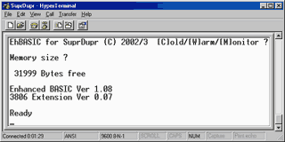
 Enhanced BASIC74 is a BASIC interpreter for the 740 microprocessor family. It is constructed to be quick and powerful and includes instructions to facilitate easy low level handling of 740 family hardware devices. It also retains most of the powerful high level instructions from similar BASICs.
EhBASIC74 is derived from EhBASIC for the 6502 and shares much of the code used in that BASIC. However EhBASIC74 also includes enhancements to make it specifically more usefull on the Mitsubishi 740 series of single chip micros. While it was developed on the M38067 it should be possible to run it on most of the 740 family with only minor modifications.
EhBASIC74 is free but not copyright free. For non commercial use there is only one restriction, any derivative work should include, in any binary image distributed, the string “Derived from EhBASIC” and in any distribution that includes human readable files file that includes the above string in a human readable form e.g. not as a comment in an HTML file.
- Language reference
- Code examples
19th June 2003.
Confusingly the main version number is now the 3806 specific version number so, while the generic BASIC version is still 1.09, this incarnation is 1.10.This adds an interrupt driven receive buffer and an extra command to help use it. Go see the language reference for details.
18th June 2003.
This is the last version for the SuprDupr and SuprChip boards that will use polled input. The next version will have an interrupt driven Rx buffer for better response. As such version 1.09 will remain available for download here.
 AT keyboard interface driver
The SuprDupr has a PS2 style socket for an AT keyboard. However, as it arrived, the data and clock go to the GAL and so were jumped directly to port 7, bits 7 and 6, on the micro. There are also positions for pullup resistors on both the keyboard data and clock lines, these are not needed and were omitted. These details may have changed as this was an early production board.
The software is unfinished and provided as a starting point for anyone who wishes to make their own. As provided the driver provides very reliable basic keyboard handling. During developement it was noticed that the keyboard driver would sometimes hang so some test code was added to monitor the reliability (included in the source but commented out) and it was found that the routine wouldn’t return about once in every 750,000 calls.
This was eventually traced to a faulty keyboard but highlighted the vunerability of the code to spurious responses from the keyboard. As a result the robustness of the code was improved by adding timeouts and the resulting code proved reliable over hundreds of millions of calls.
 LCD port driver
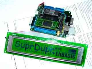
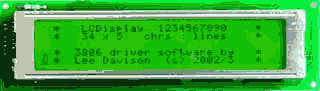
The SuprDupr has a port wired to enable use of many inteligent LC displays. The display, pictured right, is an LC7980 type though most of the other graphics and
text types are similarly driven.
One change needed to be made to the SuprDupr to use this display and that was to disconnect the earthy end of the contrast pot from 0v and connect it to the -ve
charge pump output on the MAX232 chip. This is because the greater multiplex on these graphics displays requires a more -ve bias to maintain the viewing angle.
A down side to this is that display contrast is effected by the loading on the RS232 port and use of such things as a RS232 line monitor can have an adverse
effect on the display. Also if the load from the display is to great then the MAX232 charge pump will not start. However this should not be a problem in normal use.
Another change made to the SuprDupr was to wire +12v to the spare pin on the LCD port to provide power for the backlight. This could be connected through a PNP
transistor and controlled by software via one of the port pins.
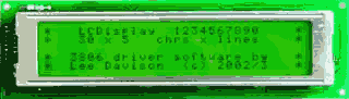
The software is unfinished and provided as a starting point for anyone who wishes to make their own. It is usable and was used to produce the displays pictured above and below.


 8 Bit ISA slot
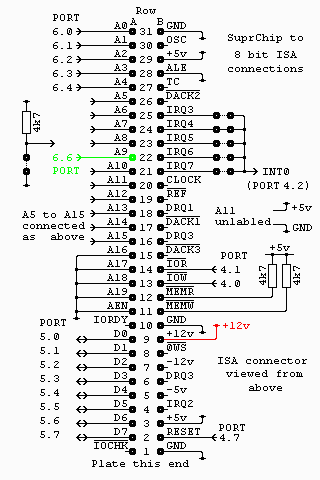
I wanted a quick way to connect an 8 bit ISA slot, only to access the IO adresse range, to the SuprChip V microcontroller. The circuit I came up with appears on the right.
The address lines A5 to A15 can either be set using jumpers or switches (I used switches) or, if you only need one address range, can be hard wired to the corresponding address.
Any of the five interrupt lines, from IRQ3 to IRQ7, can be selected by the use of a jumper. Again if you will only need one (or none) of these then the desired interrupt can be hard wired.
This circuit could be fairly easily adapted as a memory mapped device by connecting the corresponding address and data lines (possibly through buffers), by driving the IOR and IOW pins with decoded read and write signals, and by connecting the interrupt, via an invertor, to the NMI input on the processor. The RESET line can be driven, again via an invertor, by the processor RESET line or by an output port line. This line is active high.
While experimenting with different network cards I discovered some of them need the +12v supply in addition to the +5v supply. This additional connection is shown in red on the diagram.
As I had a stack of 3Com 3C509B NICs of various types I decided to try to use them. Well it turns out that even with PnP disabled you still need to access the card’s id port on $01xx. To allow this Port 6 bit 6 was connected to the A9 line, so both $03xx and $01xx can be accessed by the software. This additional connection is shown in green on the diagram.
Though the slot can be accessed entirely from EhBASIC it was decided to create two short routines to make accessing the slot faster and easier. To that end one function, to read a byte, and one subroutine, to write a byte, were written.
After initialising the function and subroutine addresses thus ..
..
30 DOKE $44,$EF20 : REM USR(n) = read from IO address $xxnn
31 rr = $EF00 : REM call address for write to IO address
..
It is a simple matter to write a byte by doing ..
20500 CALL rr,cr,dd : REM set control register
20505 REM cr is the IO address - $00 to $1F
20510 REM dd is the byte value for that IO address
.. and read a byte by doing ..
10050 by = USR(cr)
10055 REM cr is the IO address - $00 to $1F
10060 REM the byte value is returned to by
You can download the assembly source for the read and write routines.