
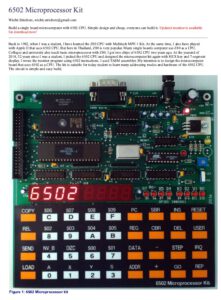
Design and text by Wichit Sirichote. Full text and files at his website here. The kit is available for sale, kit or assembled.
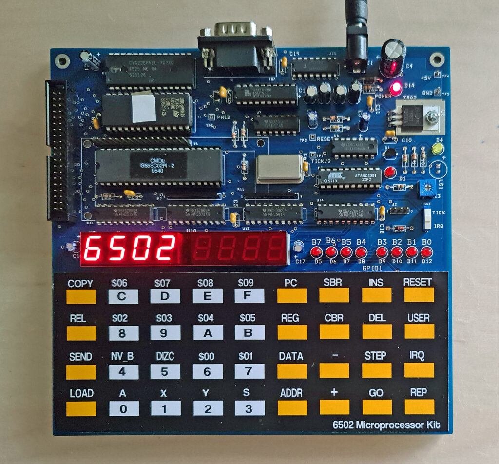
Wichit picked the 65C02 CPU and designed the microcomputer kit with HEX keys and 7-segment LED displays, wrote the monitor program using 6502 instructions. with the TASM assembler. The circuit is simple and easy build.
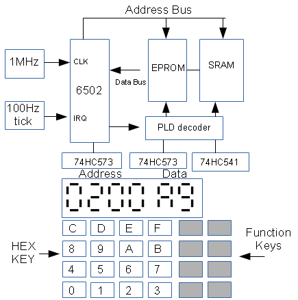
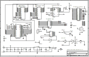
Hardware specification:
1. CPU: 65SC02, CMOS 8-bit @1MHz clock (a G65SC02 in my kit)
2. Memory: 32kB RAM, 16kB EPROM
3. Decoder chip: GAL16V8 PLD
4. Display: 6-digit 7-segment LED
5 . Keyboard: 36 keys
6 . RS232 port: 2400 bit/s
7 . Debugging LED: 8-bit GPIO1 LED
8 . SystemTick: 10ms tick
9. Text LCD interface: direct CPU bus interface text LCD
10. Expansion header: 40-pin header
Software descriptions: The monitor program was written in 6502 assembly. The source code was translated to hex code using TASM assembler. Main body is a forever loop scanning keyboard and 7-segment display. When a key is pressed the associated functions will be serviced. Details are explained as the comments in the source code.
The monitor program features are:
1.Memory contents can be edited directly with hex keys.
2. User registers for program testing
3. Single instruction execution, no need for jumpers.
4. Relative byte calculation,
5. Download hex file,
6. Zero page display.
7. Inspection of registers, processor status flags and more.
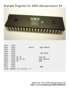
All sources are supplied, with TASM assembler syntax.
The kit I have is running monitor version 1, the current monitor of 2021 is version 4. Easy to burn into the EPROM or you can load it into RAM for debugging/testing a new version.
Downloads


Serial I/O
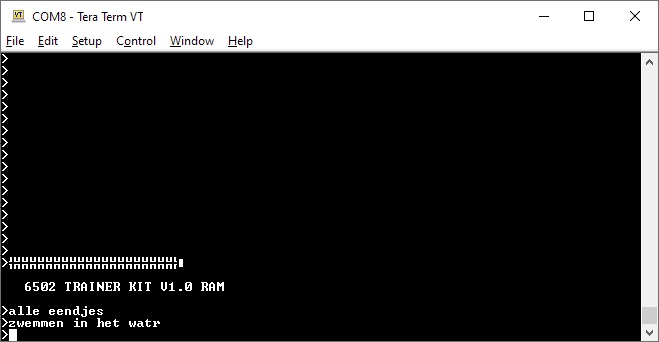
The monitor has routines for bit banged serial I/O (at RS232C levels) at 2400 baud. The monitor offers Intel Hex and MOS papertape format up/download. This makes it easy to cross develop software, edit and assemble, the download the object on a Tera term terminal session for example.
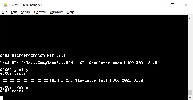
The serial routines are bit banged, the output line is shared with the little speaker. This means there is quite some noise from the speaker when serial output is done, and when the speaker is activated (e.g. when you press Reset) the serial output shows annoying trash, as you can see in the following screenshot.
You also see in the screenshot it can be used to run terminal based programs on the serial I/O. Once the program is limited to serial I/O it is fine.
Porting KIM-1 programs mean there is no hardware echo problem, so you have to do the echo yourself. Also serial I/O uses zeropage (RED_D, REG_E) $80 and $81. That may mean you have to use your own serial I/O routines, copied from the monitor but using more appropriate zeropage addresses,
How to use the serial I/O.
Note that zeropage is on the kit free from 0 to $7F!
The routines in the 6502 microprocessor kit use all registers during the bit banging output.
So it is important to save them before and restore afterwards. The following code fragments (used in the second screenshot, part of the CPU test routines in the KIm-1 Simulator achieve that.
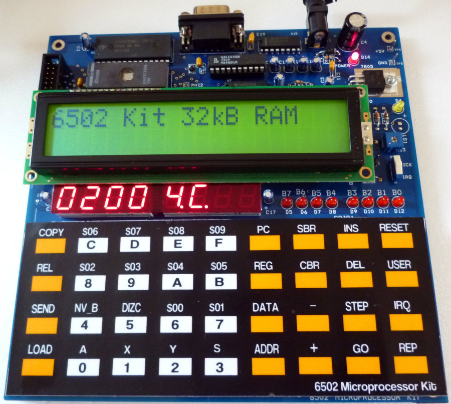
THe 6502 microprocessor has a connector for LCD displays. Example source is included.
ysave = $00  ; zeropage, choose appropriate location!
xsave = $01
asave = $03
; 6502 kit character I/O
;
XGETCH = $C054 ; GETCH (serial)
XOUTCH = $C01E ; OUTCH (serial)

OUTCH
 STA asave
 STY ysave
 STX xsave
 jsr XOUTCH
 LDY ysave
 LDX xsave
 LDA asave
 RTS

GETCH
 STY ysave
 STX xsave
 jsr XGETCH
 LDY ysave
 LDX xsave
 RTS
;
; 6502 CPU board test program serial
;
;
; 6502 kit monitor
;
pstring = $C08E
outch = $C01E
inch  = $C054
crlf  = $C09D
;
constants
;
CR      = $0d           ; Carriage return
;
        .org $0200

        jsr pstring     ; print version
pr
        jsr crlf
        lda #'>'        ; display prompt
        jsr outch
loopch
        jsr inch        ; read from serial in
        cmp #CR         ; end of line?
        beq pr
        jsr outch
        jmp loopch         ; loop
        .end
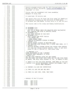
Example programs for serial I/O
0001 0000 ; This program looks at ways to determine which type of 6502-series
0002 0000 ; processor you are using. This version runs on the PAL-1 (a KIM clone).
0003 0000 ;
0004 0000 ; By Jim McClanahan, W4JBM, January 2021
0005 0000 ; adapted to 6502 kit Hans Otten, January 2022
0006 0000 ;
0007 0000 ; Build with:
0008 0000 ; $ tasm -65 <filename>.asm
0009 0000 ;
0010 0000 ;
0011 0000
0012 0000 ;
0013 0000 ; For whatever system we use, we need two routines defined:
0014 0000 ;
0015 0000 ; *** 6502 kit routine ***
0016 0000 ;
0017 0000 ; A routine to send a byte to the console...
0018 0000 outch = $C01E ; Send one byte to the output port (OUTCH)
0019 0000
0020 0000 ; Define any constants we want to use...
0021 0000 CR = $0D
0022 0000 LF = $0A
0023 0000
0024 0000 ; Location isn't particularly important...
0025 0200 .org $0200
0026 0200
0027 0200 ; Set up the stack
0028 0200 ;
0029 0200 ; This is not needed if called from a monitor
0030 0200 ;STACK: LDX #$FF
0031 0200 ; TXS
0032 0200 ;
0033 0200 ; clear kit junk
0034 0200 ;
0035 0200 A9 0D lda #CR
0036 0202 20 1E C0 jsr outch ;
0037 0205 A9 0A lda #LF
0038 0207 20 1E C0 jsr outch
0039 020A
0040 020A ; First, let's see what happens to the Zero flag in
0041 020A ; the decimal mode
0042 020A F8 TEST1: SED ; Set Decimal (BCD) Mode
0043 020B 18 CLC ; Clear the Carry Flag
0044 020C A9 99 LDA #$99 ; Load a BCD 99 (which is also $99)
0045 020E 69 01 ADC #$01 ; ...and add 1
0046 0210 08 PHP ; Push processor status byte to stack
0047 0211 8D 75 02 STA TSTR1 ; Store the result in memory
0048 0214 D8 CLD ; Because we don't want to forget
0049 0215
0050 0215 ; At this point, the Acc is $00 but the original 6502 did not
0051 0215 ; set the Zero flag when this happened in the decimal mode
0052 0215 ; while the later R6502 and 65C02 did.
0053 0215
0054 0215 F0 10 BEQ TEST1B
0055 0217 A9 79 TEST1A: LDA #MSG1 & 255 ; Point to Message 1
0056 0219 8D 6A 02 STA PRINT+1
0057 021C A9 02 LDA #MSG1 / 256
0058 021E 8D 6B 02 STA PRINT+2
0059 0221 20 67 02 JSR SHWMSG ; Display result (no Z flag)
0060 0224 4C 34 02 JMP TEST2
0061 0227
0062 0227 A9 A1 TEST1B: LDA #MSG2&255 ; Point to Message 2
0063 0229 8D 6A 02 STA PRINT+1
0064 022C A9 02 LDA #MSG2/256
0065 022E 8D 6B 02 STA PRINT+2
0066 0231 20 67 02 JSR SHWMSG ; Display result (Z flag set)
0067 0234
0068 0234 ; On the original 6502, undefined instructions could do various
0069 0234 ; (and sometimes seemingly unpredictable) things. On later versions,
0070 0234 ; some of the unused instructions were pressed into use while others
0071 0234 ; were changed to be a "safe" NOP (no operation).
0072 0234 ;
0073 0234 ; $EA is NOP and on the original most of the $xA instructions also
0074 0234 ; act as NOPs. $1A is one that seems to be a well-behaved NOP, but
0075 0234 ; the R6502 and 65C02 used that previously undefined code to
0076 0234 ; implement an INC A instruction.
0077 0234 ;
0078 0234 ; The following code checks to see what $3A does...
0079 0234
0080 0234 68 TEST2: PLA ; Before the test, let's story the processor
0081 0235 8D 76 02 STA TSTR2 ; results from the last test.
0082 0238 A9 FF LDA #$FF ; Load the accumulator
0083 023A 1A .BYTE $1A ; Either a NOP or INA (similar to INX and INY)
0084 023B 49 00 EOR #$0 ; Let's make sure the flags are set
0085 023D 08 PHP ; Save the processor status register
0086 023E 8D 77 02 STA TSTR3 ; Store result in memory
0087 0241 F0 10 BEQ TEST2B ; Does A == 0?
0088 0243 A9 C0 TEST2A: LDA #MSG3&255 ; If not, Point to Message 3
0089 0245 8D 6A 02 STA PRINT+1
0090 0248 A9 02 LDA #MSG3/256
0091 024A 8D 6B 02 STA PRINT+2
0092 024D 20 67 02 JSR SHWMSG
0093 0250 4C 60 02 JMP FINISH
0094 0253
0095 0253 A9 E1 TEST2B: LDA #MSG4&255 ; Point to Message 4
0096 0255 8D 6A 02 STA PRINT+1
0097 0258 A9 02 LDA #MSG4/256
0098 025A 8D 6B 02 STA PRINT+2
0099 025D 20 67 02 JSR SHWMSG
0100 0260
0101 0260 68 FINISH: PLA ; Let's store the processor status
0102 0261 8D 78 02 STA TSTR4 ; from the last test.
0103 0264 loop
0104 0264 4C 64 02 JMP loop ; We're done so jump back to the monitor
0105 0267 ; RTS ; ...depending on the system, RTS may work
0106 0267
0107 0267 ; If you don't want to go to the monitor, you can loop instead...
0108 0267
0109 0267 ;LOOP: JMP LOOP ; Now just loop endlessly...
0110 0267
0111 0267 ; Display a null-terminated message...
0112 0267
0113 0267 A2 00 SHWMSG: LDX #$0 ; Show Message Subroutine
0114 0269 BD 79 02 PRINT: LDA MSG1,X ; SELF MODIFYING Address and Offset
0115 026C F0 06 BEQ DONE ; Did we just load a $00 end-of-string?
0116 026E 20 1E C0 JSR outch ; If not, print it
0117 0271 E8 INX ; Point to next character
0118 0272 D0 F5 BNE PRINT ; Branch to do it again...
0119 0274 60 DONE: RTS ; Jump here at end-of-string or 256 characters
0120 0275
0121 0275 ;
0122 0275 ; If we don't have console output, you can get information on
0123 0275 ; what happened by looking at the results stored here.
0124 0275 ;
0125 0275 ; 7 4 3 0
0126 0275 ; ---- ----
0127 0275 ; NVbb DIZC
0128 0275 ;
0129 0275 ; N - Negative
0130 0275 ; V - oVerflow
0131 0275 ; D - Decimal mode
0132 0275 ; I - Interrupt disable
0133 0275 ; Z - Zero
0134 0275 ; C - Carry
0135 0275 ;
0136 0275 ; bb should be %11 (usually a $3x in these tests) to show the
0137 0275 ; status was pushed to the stack using PHP and not the result
0138 0275 ; of an interupt.
0139 0275
0140 0275 55 TSTR1 .BYTE $55 ; Result in Decimal mode of $99 + $01
0141 0276 55 TSTR2 .BYTE $55 ; ...and process status register
0142 0277 55 TSTR3 .BYTE $55 ; Result of $FF and then executing NOP/INC A
0143 0278 55 TSTR4 .BYTE $55 ; ...and the process status register
0144 0279
0145 0279 ; TSTR1, TSTR2, TSTR3, and TSTR4 should be:
0146 0279 ; $00 $39 $FF $B0 for the original 6502
0147 0279 ; $00 $3B $00 $32 for the 65C02
0148 0279
0149 0279 ; Our messages follows...
0150 0279
0151 0279 0D 0A 44 45 MSG1 .byte CR,LF,"DEC Add does not set Z. (Orig 6502)",CR,LF, 0
0151 027D 43 20 41 64
0151 0281 64 20 64 6F
0151 0285 65 73 20 6E
0151 0289 6F 74 20 73
0151 028D 65 74 20 5A
0151 0291 2E 20 28 4F
0151 0295 72 69 67 20
0151 0299 36 35 30 32
0151 029D 29 0D 0A 00
0152 02A1 0D 0A 44 45 MSG2 .byte CR,LF,"DEC Add did set Z. (65C02)",CR,LF, 0
0152 02A5 43 20 41 64
0152 02A9 64 20 64 69
0152 02AD 64 20 73 65
0152 02B1 74 20 5A 2E
0152 02B5 20 28 36 35
0152 02B9 43 30 32 29
0152 02BD 0D 0A 00
0153 02C0 24 31 41 20 MSG3 .byte "$1A acts as a NOP. (Orig 6502)",CR,LF, 0
0153 02C4 61 63 74 73
0153 02C8 20 61 73 20
0153 02CC 61 20 4E 4F
0153 02D0 50 2E 20 28
0153 02D4 4F 72 69 67
0153 02D8 20 36 35 30
0153 02DC 32 29 0D 0A
0153 02E0 00
0154 02E1 24 31 41 20 MSG4 .byte "$1A acts as INC A. (65C02)",CR,LF, 0
0154 02E5 61 63 74 73
0154 02E9 20 61 73 20
0154 02ED 49 4E 43 20
0154 02F1 41 2E 20 28
0154 02F5 36 35 43 30
0154 02F9 32 29 0D 0A
0154 02FD 00
0155 02FE
0156 02FE .END
0157 02FE
tasm: Number of errors = 0