post

KIM Venture

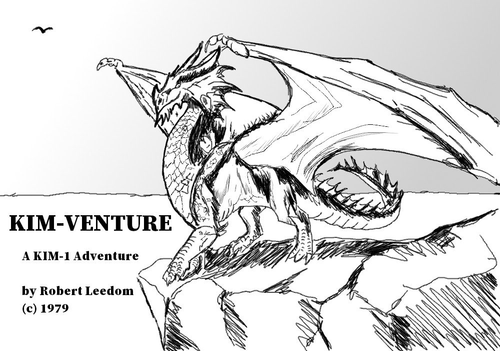
A Colossal Cave Adventure on a KIM-1? Yes, within the limits of the seven segments LED, and the 1K RAM?
The late-70s labor of love by Bob Leedom to create a mini (nano?) version of Colossal Cave Adventure is not lost.
Like Micro-Chess, amazing what can be done with the unexpanded KIM-1!

The original document with (assembled by hand!) source from Bob Leedom has been OCR’ed and converted into loadable tape and papertape files by Dominic Bumbaca and also by Mark Bush.
Dominic also made a recording on Youtube of him playing the game.

Here I present what I have now on this game:
(with thanks to Bob Leedom, Dave Wiliams, Dominic Bumbaca, Mark Bush and Nils)

PDF with instructions, source code and map (from archive.org)
Game instructions in PDF
Papertape files by Dominic Bumbaca
tape recording by Dominic Bumbaca
HEX dumps of program Dominic Bumbaca
Youtube recording by Dominic Bumbaca
Local copy the Mark Bush Github repository
Papertape files by Mark Bush
Intel hex files by Mark Bush
Assembler sources files by Mark Bush
Corrected hexpawn100 papertape thanks to Nils

Notes by Mark Bush (see his repository here)

KIM-Venture

KIM-Venture is an adventure game based on Colossal Cave written for the KIM-1. The program and its documentation are Copyright © Robert Leedom and we make no claims to any of this material. I (Mark Bush) have gathered everything together here for posterity.

Installing and Running

Included here are both paper tape and HEX format files. The HEX files can be used on a KIM-1 clone from [Corsham Tech](https://www.corshamtech.com), especially if you have their SD card system.

Load the `Venture-ZeroPage`, `Venture-Game`, and `Venture-Extra` files in any order.

Start the game by going to address `$0100` and pressing `GO`.

When you are finished, load `Venture-Scoring` and run from `$0100` to see how you did.

Note that the scoring program overwrites some page zero locations. If you want to be able to go back to your game after seeing your score, then you will need to save page zero first, then run the scoring program, then load your saved file and also `Venture-Game` again and restart at `$0100`.

The original tape IDs of these files are:

ID | File
—|—–
A1 | Venture-ZeroPage
A2 | Venture-Game
A3 | Venture-Extra
06 | Venture-Scoring

Note for KIM-1 clone users

If you are using the KIM-1 clone, then you will not be able to load the `Venture-Game` or `Venture-Scoring` as HEX files from the SD card system completely because the extended monitor uses the stack. Load them from the paper tape files instead.

Saving a Game

You can save the state of your game by saving a copy of zero page (from `$00` to `$EE`) and making a note of the contents of location `$03BD`.

Return to the game by loading your saved file instead of the original zero page data when you load the program and setting the contents of `$03BD` to the value you noted.

For the full version mentioned below (in an expanded KIM-1), record and restore the contents of `$04BD` instead of `$03BD`.

Instructions

Included here are:

* The Instructions] for playing the game.
* The Game Manual containing information about how to load and run the game

Source Code

The `source` directory contains the original source code for the game with all original comments and formatting preserved. There is one change from the original, though. In `Game.asm` in the Main Move Loop, the original code used absolute addressing for the `INC NMBUTS` statement. [My assembler](https://github.com/markbush/6502-assembler) uses zero page addressing when possible which would make this a 2-byte instruction instead of 3-byte, so I have added a `NOP` to preserve addresses in the output.

The following files contain the source code:

File         | Content
-----        | ---------
ZeroPage.asm | data to be loaded into zero page
Light.asm    | The LIGHT subroutine which compiles into the start of zero page
Game.asm     | The actual game which loads into pages 1, 2, and 3
Extra.asm    | Some support subroutines which load into the 6530 RAM
Scoring.asm  | The scoring program

These source files (except `ZeroPage.asm`) are location agnostic.
This allows them to be recompiled into alternate addresses.

The above code can be compiled using the following files:

File                 | Content
-----                |---------
Venture-ZeroPage.asm | Combines LIGHT with the zero page data
Venture-Game.asm     | Creates the actual game
Venture-Extra.asm    | Creates the file loaded into 6530 RAM
Venture-Scoring.asm  | Creates the scoring program
Venture-Full.asm     | Creates a combined program for a KIM 
                       with extended memory (or the KIM-1 clone)

These files are necessary as the individual source files refer to locations and subroutines located in the other parts. They can only be assembled together. Each of the above files contains a directive causing only the relevant part to be output, enabling the separate program files to be created.

For the `Venture-Full` version, the game starts at `$0200` instead of `$0100` and avoids using any locations in page 1 (the 6502 stack). You can stop the program to view your score at any time. Press `ST` to stop the program and change to address `$0600` and `GO`. Press `ST` again and rejoin the game from `$0200`.

The `Venture-Full` file does not include the zero page data so that must be loaded separately and will update the location of the message table in POINTR when run. This is partly to avoid trying to load data through stack locations (which could mess up the loading process) and also to make it easier to keep copies of the zero page data in order to save the state of a game.

Saved copies of zero page from the original multi-part program can correctly be used by this full version (because it updates the location of the messages), but if you wish to use a copy of zero page from the full program with the original, then you will need to change the contents of location `$4B` to be `$03` after loading.

**NOTE**: The `Venture-Full` version is a work in progress – try it at your own risk!!

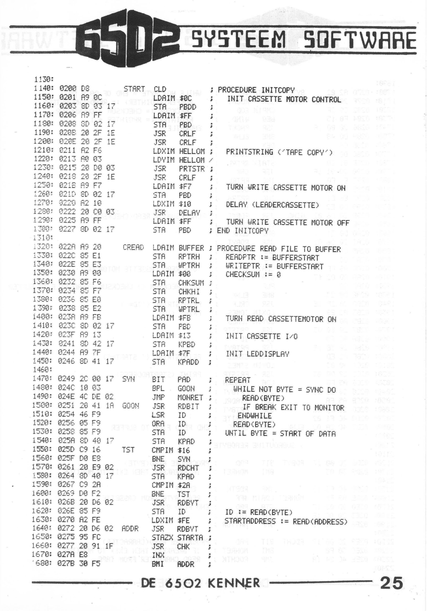
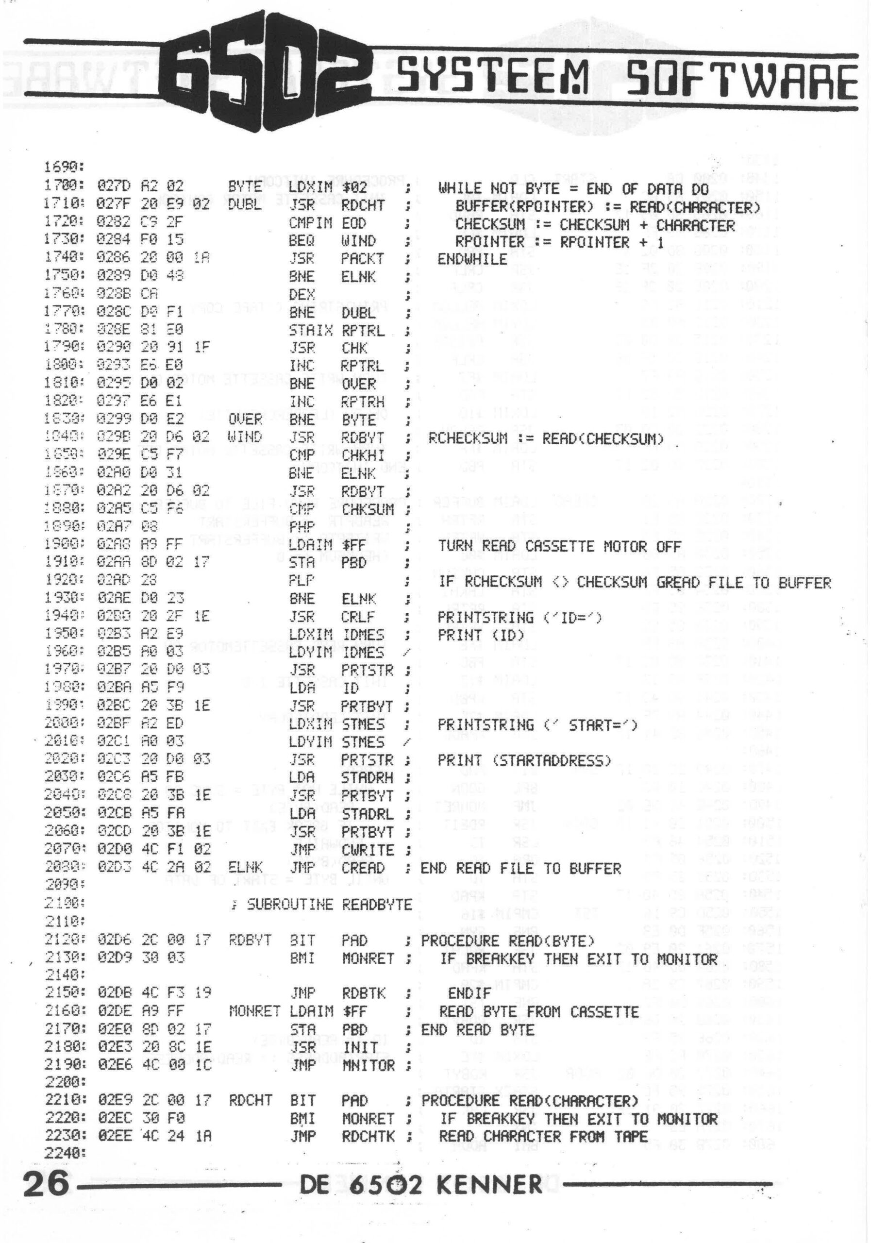
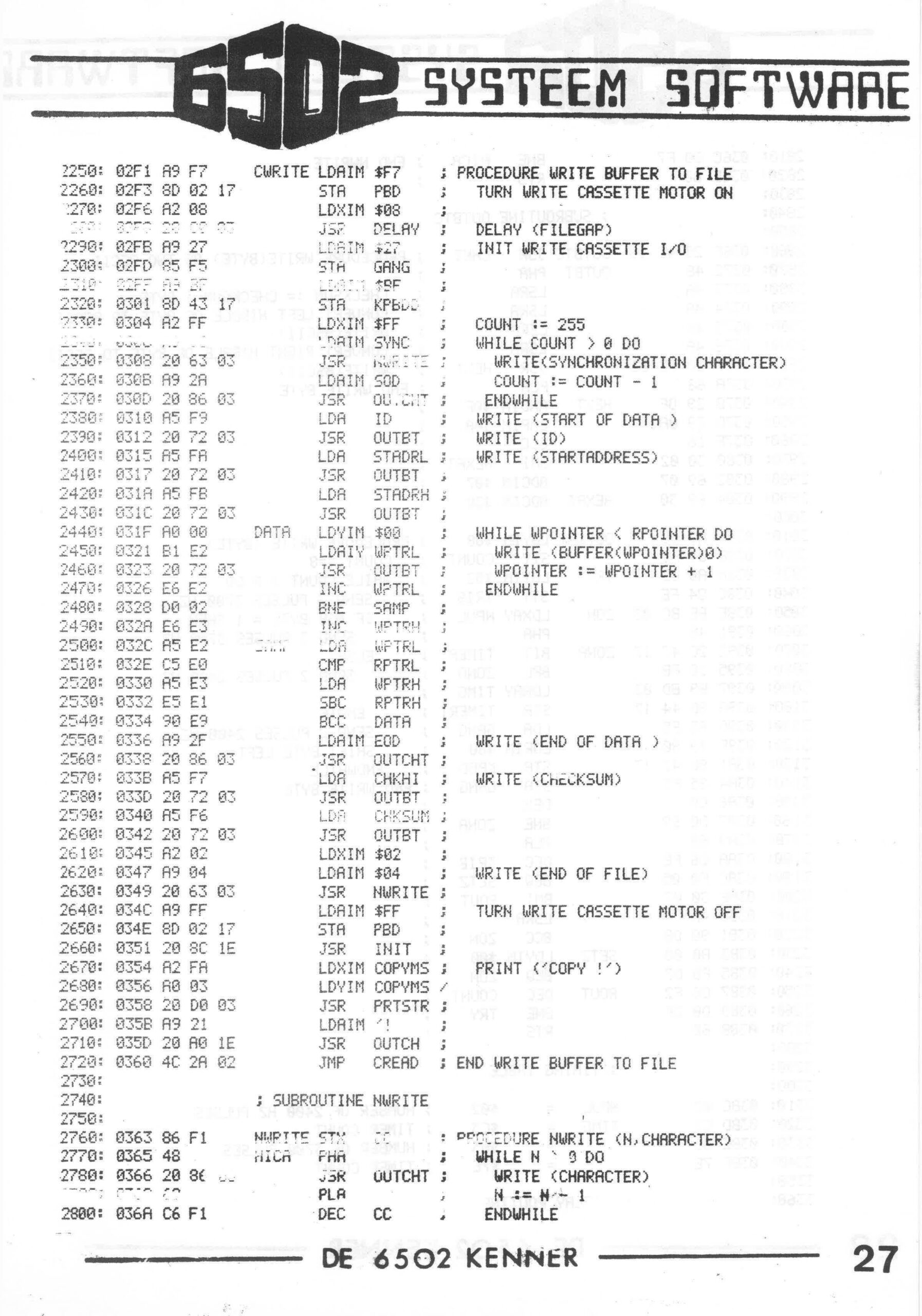
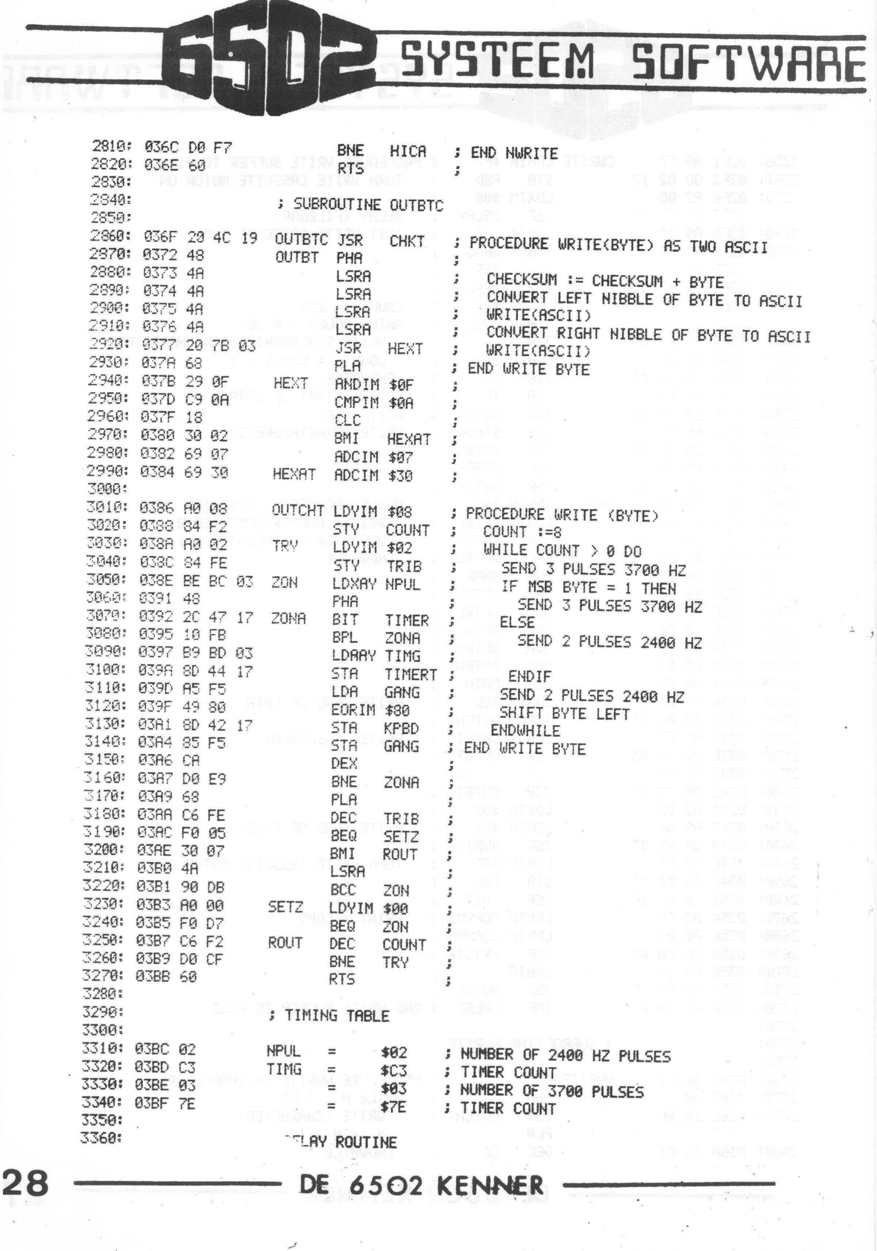
Tape copy

KIM Kenner 18 1981 Hans Otten, Translated by Hans Otten 2021, 2026

A consoleprogram to duplicate a KIM-1 cassette tape with multiple files on it. Command driven. Requires enough memory above $2000 to hold the largest file on tape (32K for example)
Version 1.1 added the Check tape command. V1.2 changed to standard KIM-1 TTY.

  • Insert cassette to duplicate in the reader drive, rewind and press play.
  • Insert cassette to write to in the write recorder, rewind, press play and play + record.
  • Start the program
  • Choose Copy or Check
    • see the reader cassette recorder playing, a tape file found and stored in memory , the progress is shown on the LED display
    • if Copy is chosen, after a file is read in the write recorder the write recorder starts recording the file
    • the file information is shown on the console: ID, start address and status (checked or copy)

    The program keeps on reading the tape, the user has to press RESET to end the program, since there is no way to see ‘end of tape’

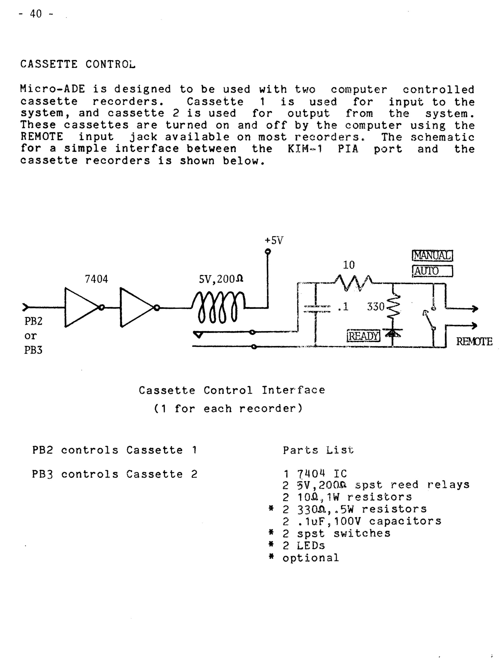
Requires two cassette recorders controlled via the Remote control, see below for the Micro Ade description of control via KIM application Port B PB2 and PB3.
V1.1 used the parallel keyboard connected to Application Port A with strobe on PA7.

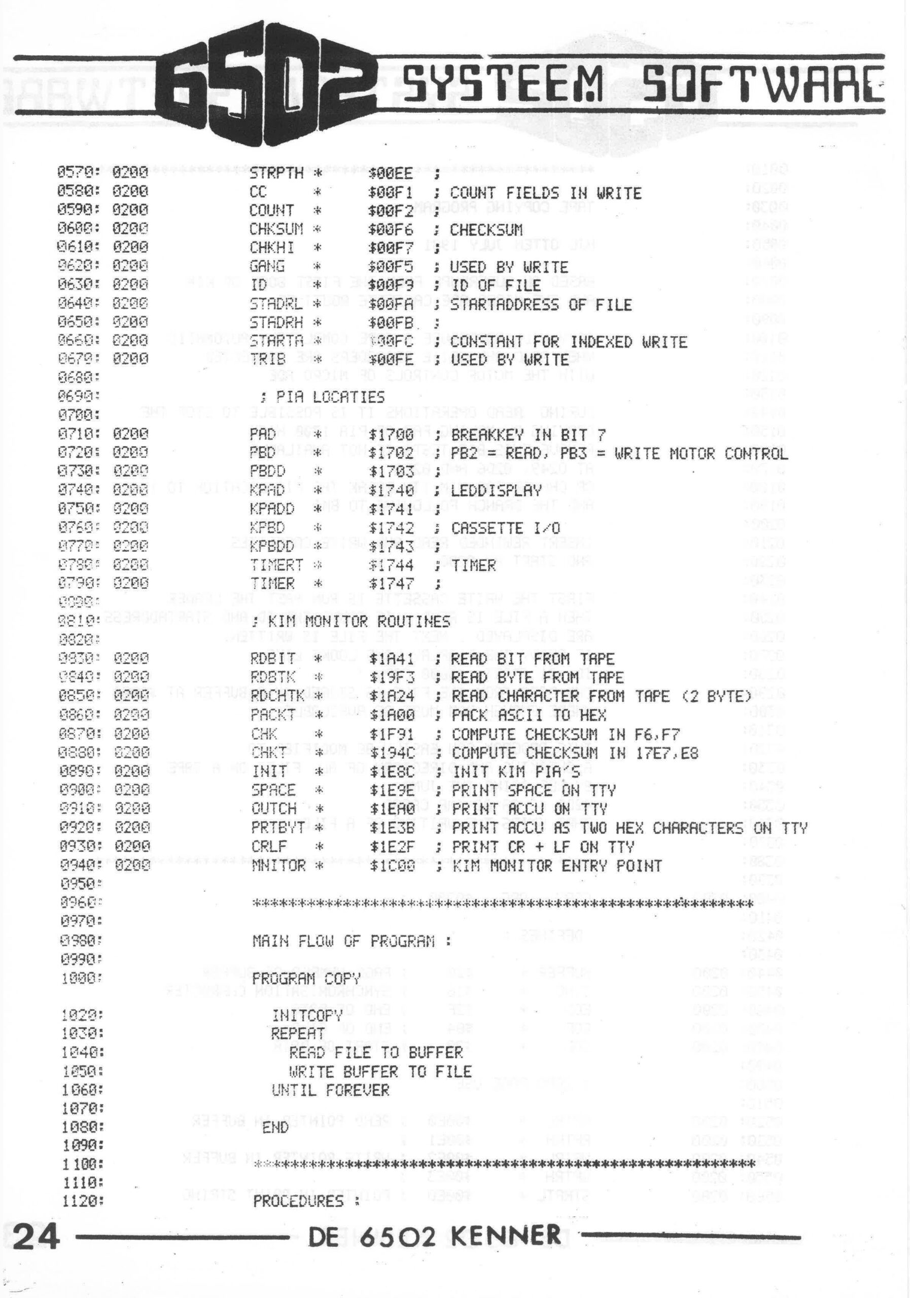
Source in MICRO ADE format and binary downloadable here.
This version served me well to copy the cassettes of the KIM Club cassette service 1980 tot 1983. Dozens of tape were reproduced this way, and were readable for many users.

Source and binary adapted to modern MOS Technology assembler format (TASM32), with small bugfixes V1.1

Source and binary adapted to modern MOS Technology assembler format (TASM32), for standard KIM-1 TTY, V1.2.

Here the original MICRO ADE V1.1 source.

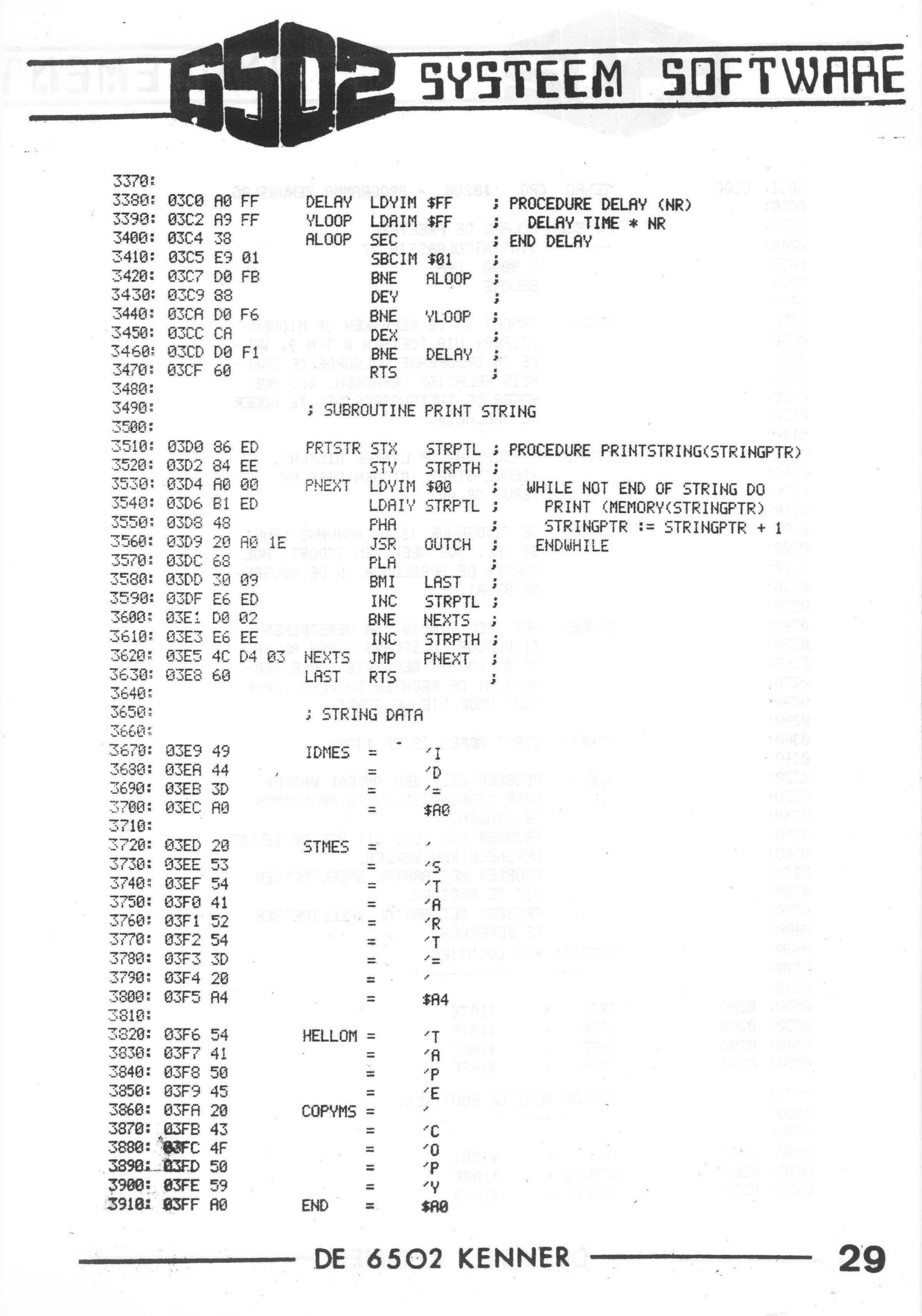
************************************

TAPE COPYING PROGRAM
;
HJC OTTEN JULY 1981 V1.0
JULY 1982 V1.1
;
BASED ON SUPERDUPE FROM THE FIRST BOOK OF KIM
AND THE MICRO ADE CASSETTE ROUTINES
;
COPY WILL REPRODUCE A TAPE COMPLETELY AUTOMATIC
WHEN READ AND WRITE RECORDERS ARE CONNECTED
WITH THE MOTOR CONTROLS OF MICRO ADE
;
DURING READ OPERATIONS IT IS POSSIBLE TO STOP THE
COPYING BY MAKING PA7 OF PIA 1700 HIGH
REMOVE THIS BIT TESTS IF NOT AVAILABLE
AT O249, 02D6 AND 02E9
OR CHANGE FOR KIM TTY BREAK THE PIA LOCATION TO 1740
AND THE BRANCH FOLLOWING TO BMI
;
INSERT REWINDED READ AND WRITE CASSETTES
AND START AT 0200
;
FIRST THE WRITE CASSETTE IS RUN PAST THE LEADER
THEN A FILE IS READ , IF FOUND THE ID AND STARTADDRESS
ARE DISPLAYED . NEXT THE FILE IS WRITTEN.
IF READY THE DISPLAY LINE LOOKS LIKE
ID= 01 START= $3600 COPY !
THE DATA FROM THE FILE IS STORED IN A BUFFER AT $2000
WHERE ENOUGH RAM MUST BE AVAILABLE
;
THIS PROGRAM CAN EASILY BE MODIFIED TO
A CHECKING AND DIRECTORY OF ALL FILES ON A TAPE
BY REPLACING THE JUMP
02D0 4C 2A 02 JMP CREAD
THAT SKIPS THE WRITING OF A FILE
;
*******************************************************
;
COPY ORG $2000 ;
;
DEFINES :
;
BUFFER * $2300 ;
SYNC * $16 ; SYNCHRONISATION CHARACTER
EOD * $2F ; END OF DATA
EOF * $04 ; END OF FILE
SOD * $2A ; START OF DATA
FF * $0C ; FORM FEED
;
; ZERO PAGE USE
HELPL * $00DD ;
HELPH * $00DE ;
CHKCOP * $00DF ; CHECK OR COPY FLAG
;
RPTRL * $00E0 ; READ POINTER IN BUFFER
RPTRH * $00E1 ;
WPTRL * $00E2 ; WRITE POINTER IN BUFFER
WPTRH * $00E3 ;
STRPTL * $00ED ; POINTER IN PRINT STRING
STRPTH * $00EE ;
CC * $00F1 ; COUNT FIELDS IN WRITE
COUNT * $00F2 ;
CHKSUM * $00F6 ; CHECKSUM
CHKHI * $00F7 ;
GANG * $00F5 ; USED BY WRITE
ID * $00F9 ; ID OF FILE
STADRL * $00FA ; STARTADDRESS OF FILE
STADRH * $00FB ;
STARTA * $00FC ; CONSTANT FOR INDEXED WRITE
TRIB * $00FE ; USED BY WRITE
;
; PIA LOCATIES
;
PAD * $1700 ; BREAKKEY IN BIT 7
PBD * $1702 ; PB2 = READ, PB3 = WRITE MOTOR CONTROL
PBDD * $1703 ;
KPAD * $1740 ; LEDDISPLAY
KPADD * $1741 ;
KPBD * $1742 ; CASSETTE I/O
KPBDD * $1743 ;
TIMERT * $1744 ; TIMER
TIMER * $1747 ;
;
; KIM MONITOR ROUTINES
;
RDBIT * $1A41 ; READ BIT FROM TAPE
RDBTK * $19F3 ; READ BYTE FROM TAPE
RDCHTK * $1A24 ; READ CHARACTER FROM TAPE (2 BYTE)
PACKT * $1A00 ; PACK ASCII TO HEX
CHK * $1F91 ; COMPUTE CHECKSUM IN F6,F7
CHKT * $194C ; COMPUTE CHECKSUM IN 17E7,E8
INIT * $1E8C ; INIT KIM PIA'S
SPACE * $1E9E ; PRINT SPACE ON TTY
OUTCH * $1EA0 ; PRINT ACCU ON TTY
PRTBYT * $1E3B ; PRINT ACCU AS TWO HEX CHARACTERS ON TTY
CRLF * $1E2F ; PRINT CR + LF ON TTY
MNITOR * $1C00 ; KIM MONITOR ENTRY POINT
;
*******************************************************
;
MAIN FLOW OF PROGRAM :
;
PROGRAM COPY
;
INITCOPY
REPEAT
READ FILE TO BUFFER
WRITE BUFFER TO FILE
UNTIL FOREVER
;
END
;
*******************************************************
;
PROCEDURES :
;
START CLD ; PROCEDURE INITCOPY
LDAIM $0C ; INIT CASSETTE MOTOR CONTROL
STA PBDD ;
LDAIM $FF ;
STA PBD ;
LDAIM FF ; CLEARSCREEN
JSR OUTCH ;
LDXIM $FF ;
NEX DEX ;
BNE NEX ;
LDXIM HELLOM ; PRINTSTRING ('TAPE COPY')
LDYIM HELLOM /
JSR PRTSTR ;
LDXIM ANDMSG ;
LDYIM ANDMSG /
JSR PRTSTR ;
LDXIM CHKMSG ;
LDYIM CHKMSG /
JSR PRTSTR ;
LDXIM VRSMSG ;
LDYIM VRSMSG /
JSR PRTSTR ;
JSR CRLF ;
JSR CRLF ;
LDXIM CHKMSG ; PRINT ('CHECK OR COPY)
LDYIM CHKMSG /
JSR PRTSTR ;
LDXIM ONLMSG ;
LDYIM ONLMSG /
JSR PRTSTR ;
LDAIM $00 ; CHKCOP FLAG = COPY
STA CHKCOP ;
JSR GETCH ; WAIT FOR ANSWER
PHA ;
JSR OUTCH ; ECHO CHARACTER
JSR CRLF ;
PLA ;
CMPIM 'Y ;
BNE NOCHK ; IF CHAR <> Y THEN COPY
LDAIM $FF ;
STA CHKCOP ;
LDXIM CHKMSG ; PRINT CHECK
LDYIM CHKMSG /
JSR PRTSTR ;
JMP CREAD ;
NOCHK LDXIM COPYMS ;
LDYIM COPYMS /
JSR PRTSTR ; PRINT COPY
LDAIM $F7 ; TURN WRITE CASSETTE MOTOR ON
STA PBD ;
LDXIM $10 ; DELAY (LEADERCASSETTE)
JSR DELAY ;
LDAIM $FF ; TURN WRITE CASSETTE MOTOR OFF
STA PBD ; END INITCOPY

CREAD LDAIM BUFFER / PROCEDURE READ FILE TO BUFFER
STA RPTRH ; READPTR := BUFFERSTART
STA WPTRH ; WRITEPTR := BUFFERSTART
LDAIM $00 ; CHECKSUM := 0
STA CHKSUM ;
STA CHKHI ;
LDAIM BUFFER ;
STA RPTRL ;
STA WPTRL ;
LDAIM $FB ; TURN READ CASSETTEMOTOR ON
STA PBD ;
LDAIM $13 ; INIT CASSETTE I/O
STA KPBD ;
LDAIM $7F ; INIT LEDDISPLAY
STA KPADD ;

SYN BIT PAD ; REPEAT
BPL GOON ; WHILE NOT BYTE = SYNC DO
JMP MONRET ; READ(BYTE)
GOON JSR RDBIT ; IF BREAK EXIT TO MONITOR
LSR ID ; ENDWHILE
ORA ID ; READ(BYTE)
STA ID ; UNTIL BYTE = START OF DATA
STA KPAD ;
TST CMPIM $16 ;
BNE SYN ;
JSR RDCHT ;
STA KPAD ;
CMPIM $2A ;
BNE TST ;
JSR RDBYT ;
STA ID ; ID := READ(BYTE)
LDXIM $FE ; STARTADDRESS := READ(ADDRESS)
ADDR JSR RDBYT ;
STAZX STARTA ;
JSR CHK ;
INX ;
BMI ADDR ;
;
BYTE LDXIM $02 ; WHILE NOT BYTE = END OF DATA DO
DUBL JSR RDCHT ; BUFFER(RPOINTER) := READ(CHARACTER)
CMPIM EOD ; CHECKSUM := CHECKSUM + CHARACTER
BEQ WIND ; RPOINTER := RPOINTER + 1
JSR PACKT ; ENDWHILE
BNE ELNK ;
DEX ;
BNE DUBL ;
STAIX RPTRL ;
JSR CHK ;
INC RPTRL ;
BNE OVER ;
INC RPTRH ;
OVER BNE BYTE ;
WIND JSR RDBYT ; RCHECKSUM := READ(CHECKSUM)
CMP CHKHI ;
BNE ELNK ;
JSR RDBYT ;
CMP CHKSUM ;
PHP ;
LDAIM $FF ; TURN READ CASSETTE MOTOR OFF
STA PBD ;
PLP ; IF RCHECKSUM <> CHECKSUM GREAD FILE TO BUFFER
BNE ELNK ;
JSR CRLF ; PRINTSTRING ('ID=')
LDXIM IDMES ; PRINT (ID)
LDYIM IDMES /
JSR PRTSTR ;
LDA ID ;
JSR PRTBYT ;
LDXIM STMES ; PRINTSTRING (' START=')
LDYIM STMES /
JSR PRTSTR ; PRINT (STARTADDRESS)
LDA STADRH ;
JSR PRTBYT ;
LDA STADRL ;
JSR PRTBYT ;
LDXIM ENMSG ; PRINT ('END = ')
LDYIM ENMSG /
JSR PRTSTR ;
SEC ;
LDA RPTRL ; HELP := READPOINTER - BEGINBUFFER
SBCIM BUFFER ;
STA HELPL ;
LDA RPTRH ;
SBCIM BUFFER /
STA HELPH ;
CLC ; HELP := HELP + STARTADDRESS
LDA HELPL ;
ADC STADRL ;
STA HELPL ;
LDA HELPH ;
ADC STADRH ;
JSR PRTBYT ;
LDA HELPL ;
JSR PRTBYT ;
LDA CHKCOP ;
BNE ELNK ; IF CHECKCOPY FLAG <> THEN CHECK ONLY
JMP CWRITE ;
ELNK JMP CREAD ; END READ FILE TO BUFFER
;
; SUBROUTINE READBYTE
;
RDBYT BIT PAD ; PROCEDURE READ(BYTE)
BMI MONRET ; IF BREAKKEY THEN EXIT TO MONITOR
;
JMP RDBTK ; ENDIF
MONRET LDAIM $FF ; READ BYTE FROM CASSETTE
STA PBD ; END READ BYTE
JSR INIT ;
JMP MNITOR ;

RDCHT BIT PAD ; PROCEDURE READ(CHARACTER)
BMI MONRET ; IF BREAKKEY THEN EXIT TO MONITOR
JMP RDCHTK ; READ CHARACTER FROM TAPE

CWRITE LDAIM $F7 ; PROCEDURE WRITE BUFFER TO FILE
STA PBD ; TURN WRITE CASSETTE MOTOR ON
LDXIM $08 ;
JSR DELAY ; DELAY (FILEGAP)
LDAIM $27 ; INIT WRITE CASSETTE I/O
STA GANG ;
LDAIM $BF ;
STA KPBDD ;
LDXIM $FF ; COUNT := 255
LDAIM SYNC ; WHILE COUNT > 0 DO
JSR NWRITE ; WRITE(SYNCHRONIZATION CHARACTER)
LDAIM SOD ; COUNT := COUNT - 1
JSR OUTCHT ; ENDWHILE
LDA ID ; WRITE (START OF DATA )
JSR OUTBT ; WRITE (ID)
LDA STADRL ; WRITE (STARTADDRESS)
JSR OUTBT ;
LDA STADRH ;
JSR OUTBT ;
DATA LDYIM $00 ; WHILE WPOINTER < RPOINTER DO
LDAIY WPTRL ; WRITE (BUFFER(WPOINTER)0)
JSR OUTBT ; WPOINTER := WPOINTER + 1
INC WPTRL ; ENDWHILE
BNE SAMP ;
INC WPTRH ;
SAMP LDA WPTRL ;
CMP RPTRL ;
LDA WPTRH ;
SBC RPTRH ;
BCC DATA ;
LDAIM EOD ; WRITE (END OF DATA )
JSR OUTCHT ;
LDA CHKHI ; WRITE (CHECKSUM)
JSR OUTBT ;
LDA CHKSUM ;
JSR OUTBT ;
LDXIM $02 ;
LDAIM $04 ; WRITE (END OF FILE)
JSR NWRITE ;
LDAIM $FF ; TURN WRITE CASSETTE MOTOR OFF
STA PBD ;
JSR INIT ;
LDXIM COPYMS ; PRINT ('COPY !')
LDYIM COPYMS /
JSR PRTSTR ;
LDAIM '! ;
JSR OUTCH ;
JMP CREAD ; END WRITE BUFFER TO FILE
;
; SUBROUTINE NWRITE
;
NWRITE STX CC ; PROCEDURE NWRITE (N,CHARACTER)
HICA PHA ; WHILE N > 0 DO
JSR OUTCHT ; WRITE (CHARACTER)
PLA ; N := N - 1
DEC CC ; ENDWHILE
BNE HICA ; END NWRITE
RTS ;
;
; SUBROUTINE OUTBTC
;
OUTBTC JSR CHKT ; PROCEDURE WRITE(BYTE) AS TWO ASCII
OUTBT PHA ;
LSRA ; CHECKSUM := CHECKSUM + BYTE
LSRA ; CONVERT LEFT NIBBLE OF BYTE TO ASCII
LSRA ; WRITE(ASCII)
LSRA ; CONVERT RIGHT NIBBLE OF BYTE TO ASCII
JSR HEXT ; WRITE(ASCII)
PLA ; END WRITE BYTE
HEXT ANDIM $0F ;
CMPIM $0A ;
CLC ;
BMI HEXAT ;
ADCIM $07 ;
HEXAT ADCIM $30 ;

OUTCHT LDYIM $08 ; PROCEDURE WRITE (BYTE)
STY COUNT ; COUNT :=8
TRY LDYIM $02 ; WHILE COUNT > 0 DO
STY TRIB ; SEND 3 PULSES 3700 HZ
ZON LDXAY NPUL ; IF MSB BYTE = 1 THEN
PHA ; SEND 3 PULSES 3700 HZ
ZONA BIT TIMER ; ELSE
BPL ZONA ; SEND 2 PULSES 2400 HZ
LDAAY TIMG ;
STA TIMERT ; ENDIF
LDA GANG ; SEND 2 PULSES 2400 HZ
EORIM $80 ; SHIFT BYTE LEFT
STA KPBD ; ENDWHILE
STA GANG ; END WRITE BYTE
DEX ;
BNE ZONA ;
PLA ;
DEC TRIB ;
BEQ SETZ ;
BMI ROUT ;
LSRA ;
BCC ZON ;
SETZ LDYIM $00 ;
BEQ ZON ;
ROUT DEC COUNT ;
BNE TRY ;
RTS ;
;
; TIMING TABLE
;
NPUL = $02 ; NUMBER OF 2400 HZ PULSES
TIMG = $C3 ; TIMER COUNT
= $03 ; NUMBER OF 3700 PULSES
= $7E ; TIMER COUNT
;
; DELAY ROUTINE
;
DELAY LDYIM $FF ; PROCEDURE DELAY (NR)
YLOOP LDAIM $FF ; DELAY TIME * NR
ALOOP SEC ; END DELAY
SBCIM $01 ;
BNE ALOOP ;
DEY ;
BNE YLOOP ;
DEX ;
BNE DELAY ;
RTS ;
;
; SUBROUTINE PRINT STRING
;
PRTSTR STX STRPTL ; PROCEDURE PRINTSTRING(STRINGPTR)
STY STRPTH ;
PNEXT LDYIM $00 ; WHILE NOT END OF STRING DO
LDAIY STRPTL ; PRINT (MEMORY(STRINGPTR)
PHA ; STRINGPTR := STRINGPTR + 1
JSR OUTCH ; ENDWHILE
PLA ;
BMI LAST ;
INC STRPTL ;
BNE NEXTS ;
INC STRPTH ;
NEXTS JMP PNEXT ;
LAST RTS ;
;
; SUBROUTINE GET CHARACTER
;
GETCH BIT PAD ; PROCEDURE GETCHARACTER ( CHAR )
BPL GETCH ; WAIT FOR STROBE
GWAIT BIT PAD ; WAIT FOR END OF STROBE 
BMI GWAIT ;
LDA PAD ; GET CHARACTER
RTS ; END GETCHARACTER
;
; STRING DATA
;
IDMES = 'I
= 'D
= '=
= $A0
;
STMES = '
= 'S
= 'T
= '=
= $A0
;
ENMSG = '
= 'E
= 'N
= '=
= $A0
;
HELLOM = 'T
= 'A
= 'P
= 'E
COPYMS = '
= 'C
= 'O
= 'P
= 'Y
= $A0
;
;
CHKMSG = 'C
= 'H
= 'E
= 'C
= 'K
= $A0
ONLMSG = 'O
= 'N
= 'L
= 'Y
= '
= '?
= $A0
VRSMSG = 'V
= '1
= '.
= '1
= $A0
;
ANDMSG = 'A
= 'N
= 'D ;
= $A0


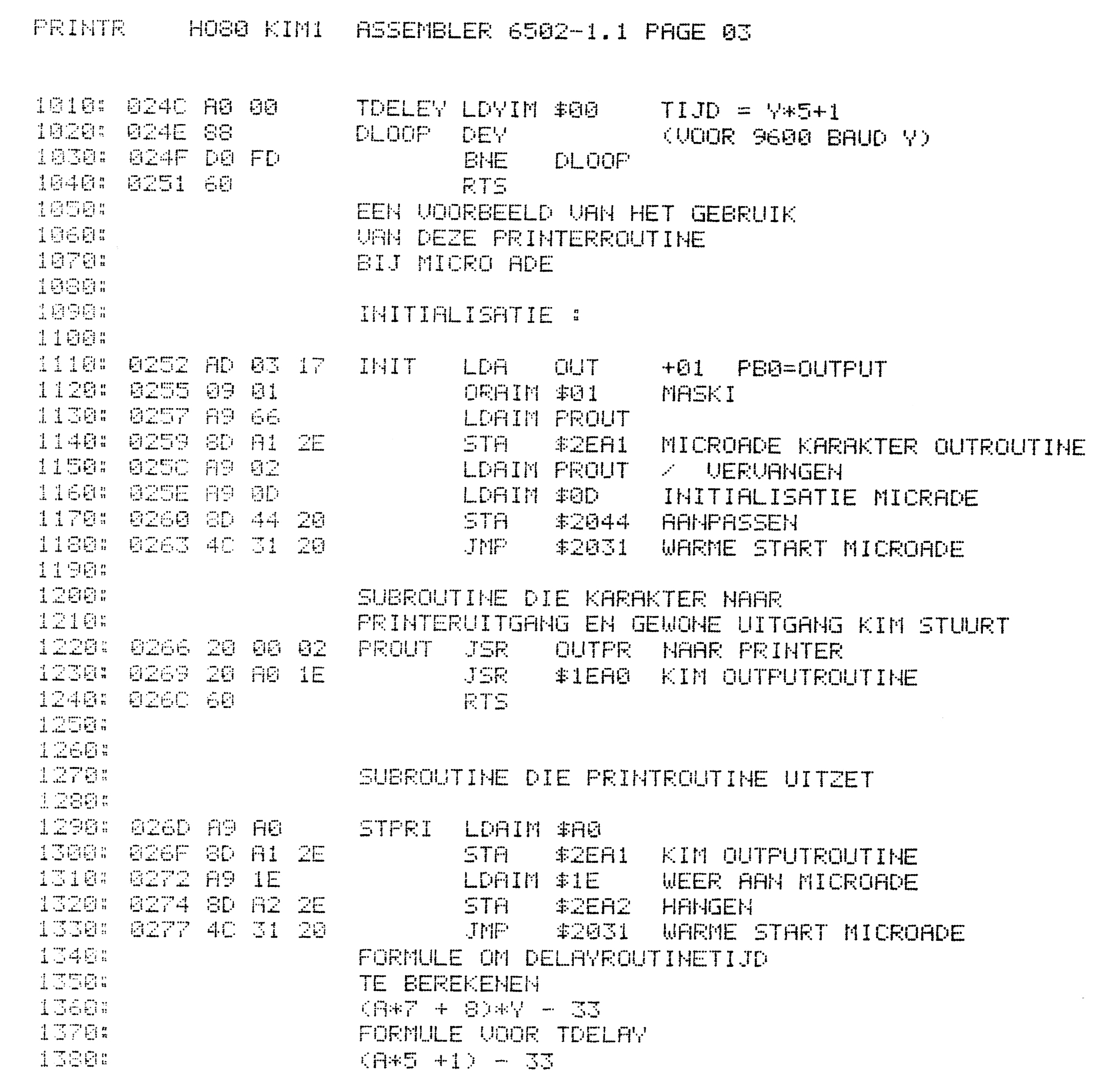
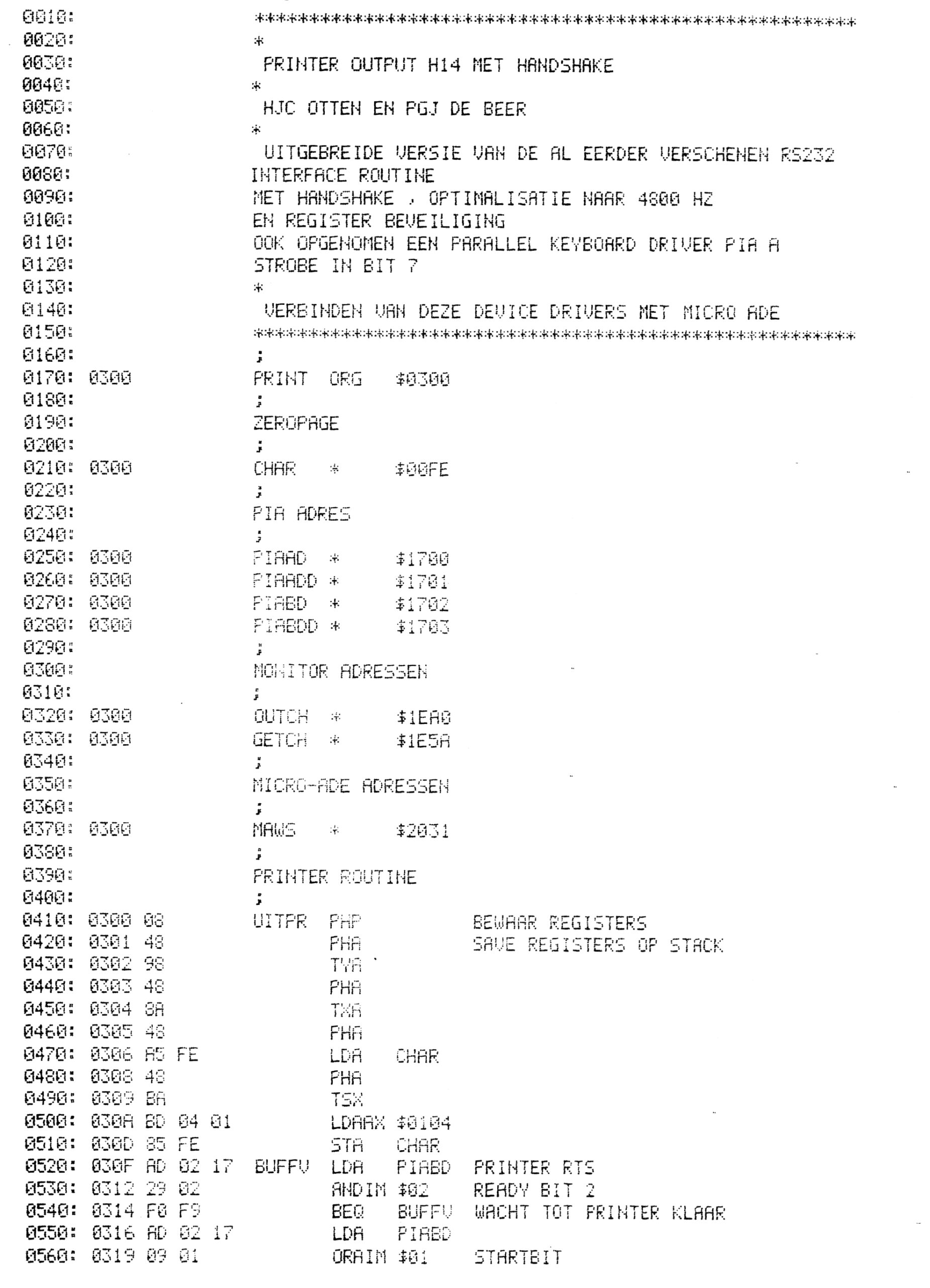
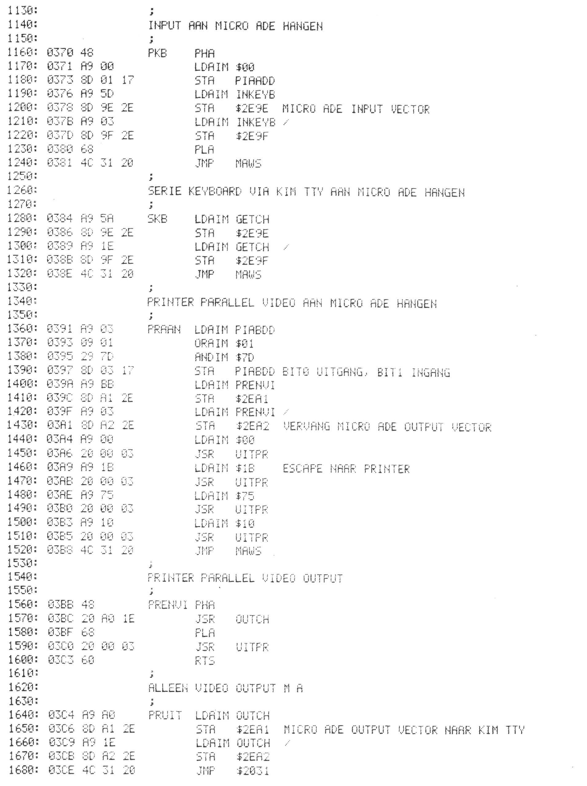
KIM-1 printer output RS232 H14

Based upon original articles KIM Kenner 13 1980, 6502 Kenner 19 1981: Hans Otten and PGJ de Beer Translated Hans Otten 2021

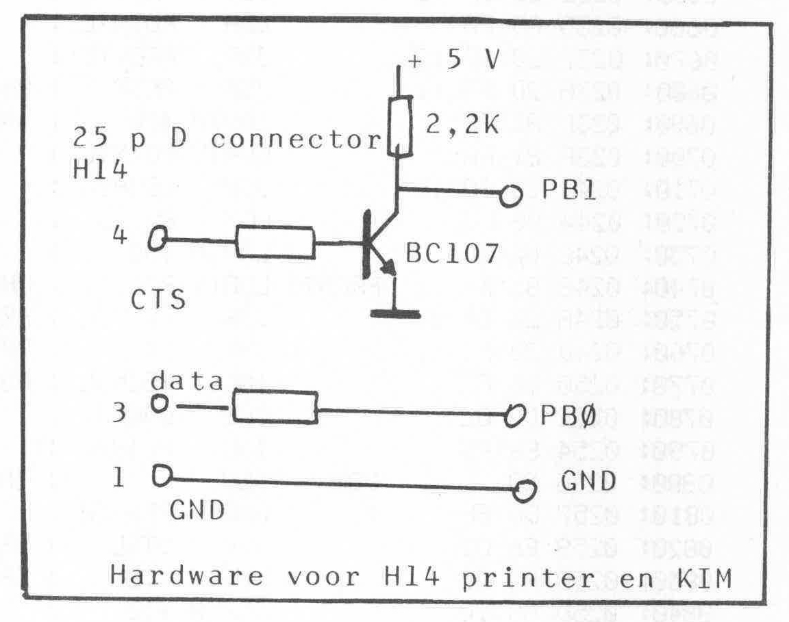
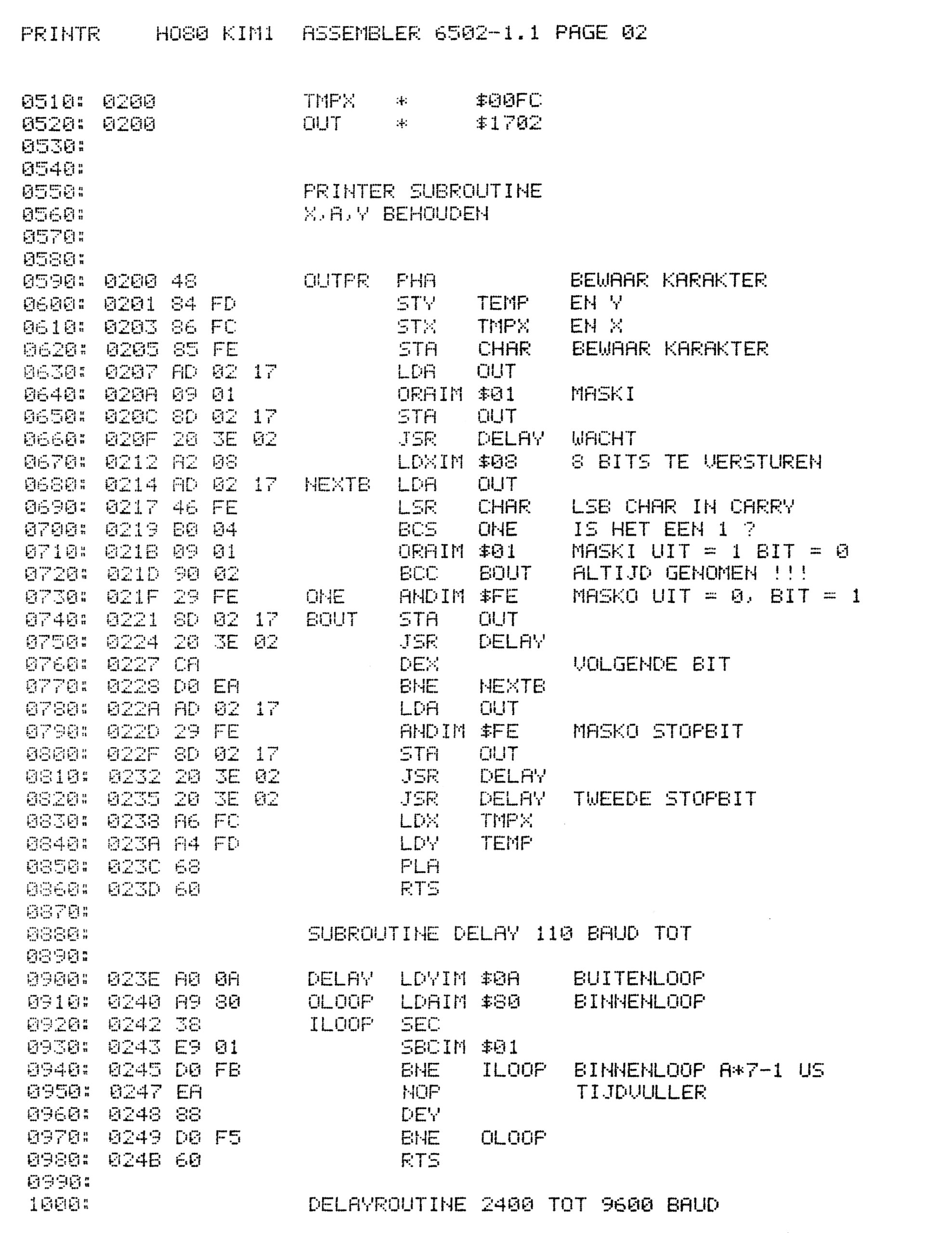
In two articles a routine to send a character via serial to a printer (or any serial device) and interface this routine to Micro Ade.
The second version allows for handshake signal CTS.
Baudrate may vary from 300 to 9600 baud. Only one or two (handshake) PIA bits are necessary, the serial signal is composed with bit banging.
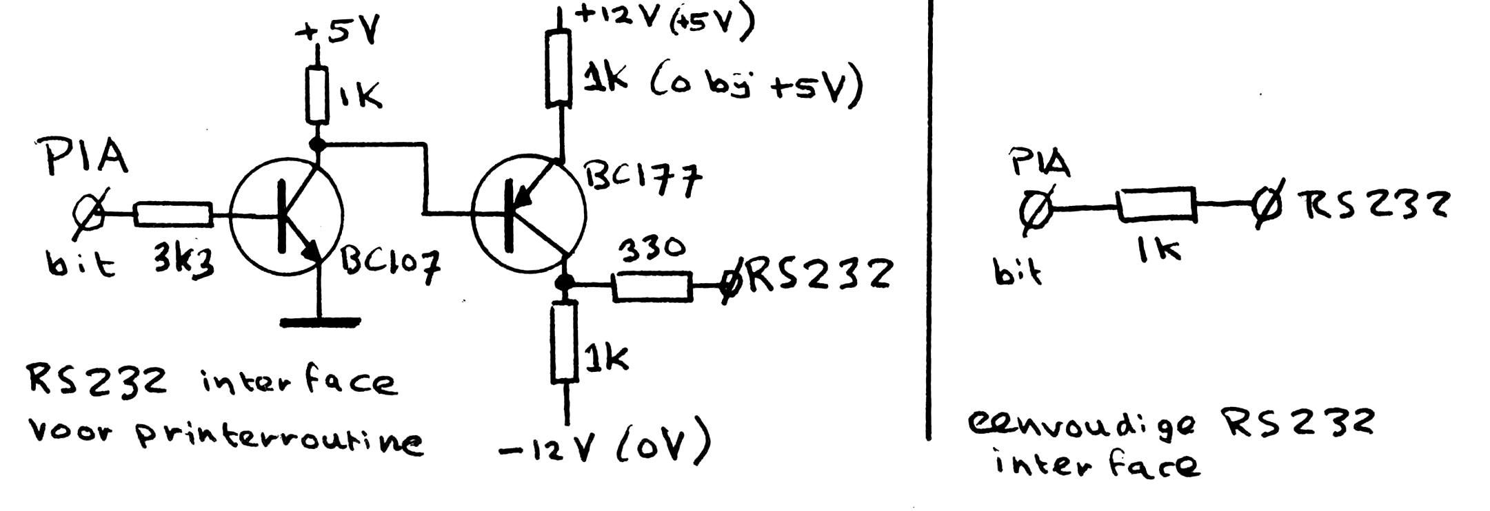
A simple hardware connection to RS232 in two variants: RS232C signal level compliant or a very simple resistor (sufficient for short distances and most printers).

Source in Micro Ade format.

First source with choice of baudrate, second fixed baudrate 4800 baud and CTS handshake.

Also a routine to read a character form a parallel keyboard connected to PIA A with strobe bit in bit 7.


Make MS Basic KB9 faster: the ROR bug

KIM Kenner 19 Patches op Basic Hans Otten, translated by Hans Otten, 20211

May 1981 Byte Magzine had an article in System Notes, Faster Basic for Ohio Scientific.
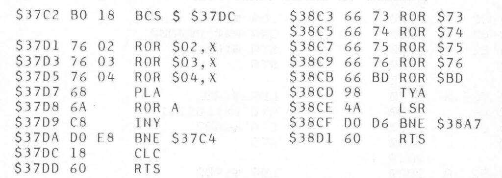
The article described how the first batch of the 6502 had a faulty ROR instruction, so the programmers of Microsoft Basic had to work around this missing instruction with a slower replacement, (Note 2021: this is well explained in the Pagetable MS Basic articles) and how to patch this to really use the ROR instruction and speed up things.

A letter to the editor in a later Byte (September 1981?) showed the patches required for the KB9 KIM-1 version.

Location $37DE to $3801 and $38D2 to $3903 are now unused.

This patch may speed up KB9 quite a bit for number crunching.


Audio tape read and write indicator

KIM Kenner 10 March 1980, Dutch article by Hans Otten, English translation Hans Otten, 2021

Having an indication of how the reading and writing to the cassette recorder is going is nice. With the Micro Ade routines the LED display is used for this. the standard KIM-1 routines are mute.
This small hardware circuit gives either a visual or audible indication with the standard KIM-1 routines.

How does it work?
An indication for for the read process is the output signal of the PLL circuit, a stream of digital pulsed delivered at PB7 of the RRIOT 6530-002. During the reading pin PB7 is rpogrammed as input, during the wirte it is an output. Via a buffer the output signal signal is brought to Audio-Out and Audio-Out-High.
The use of PB7 as input and output during the read and write process means that during a read the decoded signal appears on Audio Out, and as it is meant to be, during writing also has the output signal. Collision is prevented by blocking the input signal during writing. So this means that during reading and during write the signal is present on Audio-Out. This enables a indication of both read and write processes.


The circuit

The signal on Audio-Out (application connector A-M) is brought to a transistor (general purpose type) and the alternating signal makes the LED blink quite fast. A miniature loudspeaker can be switched in and the signal can be heard, it is in the hearable audio range. The LED is not very informative, the loudspeaker is, but also can be annoying, so the switch is welcome.

Do not use a lower value than 33 ohm for R2, it will damage the transistor. The circuit does not represent a heavy load, so you can use the KIM-1 power supply.

Construction
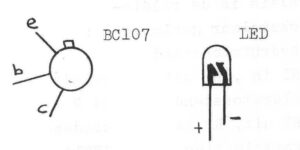
A piece of stripboard is sufficient. See the figure below for the connections of transistor and LED. Red, green, yellow can all be used.
Other usage
By programming the output PB7 music or signals can be heard.

Reading tapes from other KIM-1

KIM kenner 6 1978 Hans Otten Dutch, translation to English Hans Otten 2021

Reading tapes recorded on another KIM-1 or bought like Tiny basic, Microsoft KB-9, Miccrochess and Micro Ade was not that easy. Many many errors, especially the hypertape format.

Reading and writing of my own tapes, after having configured the PLL following the guide in the User manual, and keeping the cassette recorder clean, now is flawless. With the motor control (see Micro Ade manual appendix) it is a pleasure!

I read and tried all advices, like adjusting the azimuth of the recorder head, cleaning etc. Maybe the variations in tape speed between recorder and my player and the resulting frequency shift was a problem?
What really helped was looking with an oscilloscope at the output of the PLL (pin 7 of the LM311) we can see clearly the problem:

No real problems with noise or dropouts, just deviations between different recordings, so the PLL does not operate correctly. Bought tapes showed the pictures Wrong 1 and Wrong 2. And that leads to reading problems, the software makes the wrong decisions on ‘0’s or ‘1’s.

The following procedure was developed to read the bought tape, store it and save the program on my own tapes:

  1. Start reading the problem tape, 1873G
  2. Connect a simple voltmeter to pin 7 of the LM311 or Expansion connector-X
  3. Now change the PLL variable resistor to a reading of 2.7V. A scope would show ‘Correct’
  4. Start the read again
  5. Save the program
  6. Repeat with your own recording or the user Manual PLL set procedure

This helped me to read the problem tapes. Only for Microsoft Basic I had to play with the output volume, large variations in the recorded signal. But it worked in the end and now I have my own recordings on tape, several stored and working copies. One can never have enough backups!

PLL Test


This program write alternate two low frequency or three high frequency tones to the tape recorder.
Record this for a couple of minutes.
When reading this tape the PLL should convert this to a symmetric block pulse.


This program shows on the first two digits on the KIM-1 LED display the number of ‘1’s read, on the second two digits the number of ‘0’s read.
When all is well this should 80/80 but anything between 60/A0 and A0/60 is fine.

ASCII parallel keyboard to KIM-1

Kenner 2 page 4 July 1977 Co Filmer, translated to english Hans Otten, 2021

A parallel ASCII keyboard is a nice addition to the KIM-1.

Connect to the PIA A of the KIM-1 on the Application connector.

Some keyboards may require a -12 V power supply.

The address 1700 now shows the ASCII keyboard code of (the last) key pressed. The high bit (PB7) is the strobe signal, the other 7 bits the ASCII code.

A program should poll the strobe bit, if activated wait for the strobe bit to be deactivated, and then read the key and return.
Testing for keypressed such as a break test means checking the strobe bit, if activated stop processing, etc..

Code fragments by Hans Otten

PAD * $1700 ; BREAKKEY IN BIT 7
   ; SUBROUTINE GET CHARACTER
   ;
GETCH BIT PAD ; PROCEDURE GETCHARACTER ( CHAR ) 
 BPL GETCH ;   WAIT FOR STROBE
GWAIT BIT PAD ;   WAIT FOR END OF STROBE 
 BMI GWAIT ;
 LDA PAD ;   GET CHARACTER
 RTS  ; END GETCHARACTER
   ;
   ; example of break test
   ;
SYN BIT PAD ;   REPEAT
 BPL GOON ;     WHILE NOT keypressed
 JMP MONRET ;      
GOON continue processing

Recording programs with the KIM-1 and the cassette recorder

Original Uwe Schroeder, KIM Kenner 1, March 12 1977  Translation June 2021 Hans Otten

Introduction

A large number of KIM-1 users seem, like me, to have problems recording computer programs on the cassette recorder. For unknown reasons the KIM-1 refuses to read a program, while before it went well with the same tape. These problems have led me to study the KIM-1 system and I hope to have finally discovered the cause of the problem.
This article serves to aid other KIM-1 users to solve also these problems.

Part of the PLL circuit, including input impedances

Analysis of the KIM-1 FSK system
Signals are stored on the cassette tape with FSK (frequency Shift Keying). By consecutive high and low frequency sounds (on the KIM-1 3.6 kHz and 2.4 kHz). These high and low frequency sounds are generating not with much hardware, but with software. Reading programs is done by analyzing these sounds with the LM565 IC (a Phase Locked Loop, see User manual page 31 and fig 3.8). The fact if the sound was high or low frequency is determined after some amplification and filtering via a LM311 comparator to ‘0’ and ‘1’ and offered to I/O port PB7 of the second 6530 RRIOT).

The problems arising at the reading are probably caused by not correct functioning of the circuit around the PLL. The average cassette recorder appears to supply sometimes during a very short period a dropout to let the PLL function correctly.

Where and how things can go wrong with the PLL

  • When we record on the cassette recorder a constant tone of 3.6 kHz and listen to the recording and examine it with an oscilloscope, we see and hear the sound volume fluctuate or even disappear for short periods, we call this dropouts of the tape. These dropouts will mean a fluctuation of the sound available for the PLL to detect 10 to 100 times lower volume and cause the detection to fail. By measuring the PLL level I have seen 10 to 100% more signal than required, so that ca mean PLL malfunction.
  • If a tape is passing the head misaligned/tilted of the tape recorder head, higher frequencies are in the disadvantage and weaker. This head misalignment will cause problems with recordings from other tape recorders, bought or from other users.
  • Suppose we use a perfect +5V power supply, then VCC can be considered ‘Ground’ When we send on Audio In a AC current of 550 mV, then resistors R8 andR14 reduce the signal 1/11 of 550 Mv = 50 mV supplied to the PLL. Measurements indicate the PLL requires at least 40mV to sync the PLL and see it as a ‘high’ frequency sound.
    Remark: replace the R8 with 1K to give the PLL 250 mV instead of 50mV.
  • Suppose we use a perfect recorder with a very low output impedance. And suppose the power supply has a noise level of 600 mV. Fig 2 shows, after some calculations the noise level results in 40 mV on the PLL input. If we reduce the resistor to 1K , the noise level becomes 230 mV.

The specifications of the PLL indicate the correct functioning of the PLL at an input level of nominal 2, maximal 20 mV. The fact that the measurements indicate the PLL only operates at levels of 40 mV indicate the noise levels are at the same level as the input signal coning from the recorder. A better noise reduced may help, but other sources of interference are possible. Therefore extra amplification of the signal is preferred instead of altering the KIM-1 hardware.

Solve the tape recorder problems
Since the problems with reading of tapes on the KIM-1 seems to be related to fluctuating signal levels:

  • Record the signal as loudly as possible, use a recorder without automatic level adjustment and record so that the tape is saturated.
  • When using the loudspeaker output, experiment with the volume. But too loud means distortion and may also lead to failures.
  • Build an amplifier for frequencies 2-4 kHz 10 to 20 times, short dropouts should be well amplified.
  • Use C60 instead of C120 types. Normal cheap ferro is fine, Chrome has more dropouts.
  • If the KIM-1 reports a reading error (FFFF in the display) and you want to know how much of the tape has been read, location 17ED and 17EE contain the first address not read yet.
    Make a copy of finished programs on another cassette and check this copy for readability. Do not use this copy anymore and store it. When using a cassette often, this may lead to problems, like the mangling of the tape in the drive.

Troubleshooting
Here is a procedure to work around reading tape problems:

  1. Check if the recorder is connected to the KIM-1
  2. Check Volume and Tone control ((max high)
  3. Press Reset.
  4. Set location 17F9 to 0.
  5. Set location 00F1 to 0.
  6. Inspect location 1742. Here the information of I/O pin is shown. The display shows 1742 87
  7. Start the recorder. The middle bar of the 8 now will blink, if not : you have Error 6A (see below).
    Stop the recorder, remove the cassette and start the recorder. Now the middle bar of the 8 should not blink, else you have Error 6B (see below)
  8. If the Volume knob of your recorder controls the strength of the output signal: start the recorder and determine in which setting the blinking of the bar changes. If you have not enough headroom, see Error 7.
  9. Check of the correct detection of the high frequency.
    Type in the next program and start it (the program writes a constant tone of 3.6kHz to the recorder)
    Record this tone on the recorder for several minutes.
    Rewind the recorder and start playing. Now the display should show no middle bar 1742 07
    The bar should not blink at all, every blink indicates a dropout or such. See Error 7 and Error 8.
  10. Read User Manual C and E

Oscilloscope test
If you have an oscilloscope, do the following measurements.

  1. Attach the scope to Audio Out, e.g the negative side of C4 (user manual page B-1).
  2. If you have dual channel scope, connect the other input to the top of resistor R8, that is the PLL input.
  3. Set the timebase to 1 ms, and connect Audio-Out-High with Audio-In.
  4. Start a dump of memory with 1800G

The scope will now show figure 3.

Stop the dump program , remove the connection between Audio-In and Audio Out-High and connect the cassette recorder to the KIM-1. Start reading the tape (1873G) and move the tape to a problem area. You need to start the reading program to avoid the interference of the display. When all is right you should see the same nice picture on the scope as before.
Now increase and lower the signal level of the cassette recorder to see, if or when, there are problems with the PLL. Dropouts are visible with a image that is unstable or noise peaks. Dropouts are best studied with the 3.6 kHz recorded signal. They are visible as negative peaks on Expansion connector PLL-Test E-X. A high frequency tone is on this pin a +5V, a low as 0V.

Error 6A
The PLL is not functioning, sounds are not detected. This can be caused by:

  • No +12V power supply
  • The signal of the cassette recorder is not reaching the KIM-1
  • The signal is way too weak
  • The PLL is broken or not properly configured.
    Configuring of the PLL can be done with the program PLLCAL in Appendix I page 13
    Connect Audio-Out-High with Audio-In and start the test program on 1A6B. Inspect pin E-X PLL test on the expansion connector with a voltmeter. Adjust the variable resistor on the KIM-1 so that you see 2.5V. A small adjustment can lead to 0 to 5V, as expected.

Error 6B
The PLL is active while no input signal is present.

  • Noise signals picked up
  • Defective PLL or misconfigured of the display shows: 1742 07

Error 7
Your cassette recorder is delivering a too weak signal and you will get reading problems. See the amplifier below for a solution.
Error 8
Essential for the correct operation is the correct high frequency 3.6 kHz.

  • Dirty cassette recorder heads. Clean with a quality product
  • Unaligned head. If you are lucky there is aa small screw next to the tape head allows to adjust it, listen to a high pitch
  • Tape head is worn out, replace the cassette recorder

Amplifier between KIM-1 and the cassette recorder.

When some amplification is required the following circuit may be useful.

The amplification is controlled with variable resistor P1 from 3 to 100x. A second order Butterworth filter lowers frequencies below 2 kHz to remove mains noise.
Note the shielded cables in the drawing. Be careful to use the indicated ground point, never make a groundloop !
Place the amplifier away from noise sources and the KIM-1, noise will be amplified too!

Insert a 22 nf (22kpF in the drawing) on resistors R33 and R34 (see figure 4 right bottom and Appendix B page B1).
Adjust P2 variable resistor for Vu (output 741 opamp) = 6V
P1 controls the amplification.
The opamp (741) can be any standard general purpose audio type.
Test the amplifier as described above. Adjust for optimal volume. Record a program on tape with lower as usual volume. Try higher volume only temporarily if an error occurs.

Suppress the KIM-1 echo

A page on suppressing the KIM-1 echo of TTY input, read non-blocking and make the TTY input deaf.

Problems with the KIM-1 TTY character input

  1. The KIM-1 hardware is hardware echoing incoming serial characters to the output, no echo in software involved, so you cannot influence what appears on screen. Very annoying!
  2. The KIM-1 GETCH routine is blocking, no way to check for a character coming in, like a Break. waiting.
    Also quite annoying if porting other software to the KIM-1 or you want the program interruptable.
  3. While a program is running something CPU intensive and you type something the program is not really waiting for, the characters appear on screen. Because the KIM-1 does hardware echoing of TTY input, this is unavoidable it seems

Here I present solutions for these problems in software, made possible by the genius hardware design of the KIM-1 TTY I/O.
Are they perfect? Maybe not, it is still bitbanging the incoming serial signal. It can miss the correct starting point for the incoming character bit stream.
If you want a perfect solution, you will need interrupt driven ringbuffered serial I/O with a dedicated IC like the 6850, 6551 etc.
Without this extra hardware you can achieve acceptable results with these routines.

Background in (updated) original article KIM Kenner 17 page 14, Dutch, Hans Otten, 1980

In the KIM Kenner 1 Siep de Vries, founder of the Dutch KIM Club mentioned how in Focal-65 for the 6502 a trick was built in to suppress the hardware echo by manipulating the TTY out bit PB0. I took the idea and implemented it on my KIM-1 in 1980 without seeing the Focal code, as I did not have a Focal binary yet then!

I examined in 2003 how it was done, from the Focal disassembly I made then:

34AF  E6 76       L34AF INC $76         ; random number?
34B1  2C 40 17          BIT H1740       ; check if character is incoming
34B4  30 F9             BMI H34AF       ;=> wait until startbit
34B6  AD 42 17          LDA H1742
34B9  29 FE             AND #$FE        ; clear PA7
34BB  8D 42 17          STA H1742
34BE  20 5A 1E          JSR H1E5A       ; KIM-1 input
34C1  48                PHA
34C2  AD 42 17          LDA H1742
34C5  29 FE             AND #$FE        ; isolate PA7
34C7  09 01             ORA #$01        ; set PA7 to 1
34C9  8D 42 17          STA H1742
34CC  68                PLA
34CD  18                CLC
34CE  60                RTS

How to suppress the hardware echo to TTY out or making the TTY input deaf

The hardware echo of incoming serial signal to outgoing TTY output is shown in the next figures (from the KIM user manual and the KIM Circuit poster).
The TTY KEYBD signal goes via a transistor and NAND gate U15 to PA7 port of the 6532. That signal also goes to pin 10 input  of NAND gate U26  which is the TTY out line. This is the hardware echo. When the KIM-1 sends out a character it comes from PB0 to pin 9 of of NAND gate U26 and so comes out to the TTY Out line.
PB5 (audio TTY control) is connected via an inverter to NAND gate U15. The other input is TTY IN. Making PB5 high will make the TTY input PA7 deaf for incoming signals.


The genius designers of the KIM-1 used NAND gates in the TTY I/O!

Non-blocking input

The KIM-1 GETCH routine detects an incoming character by looking in a loop for the start bit to appear. It then reads the character.
By first doing that loop of looking for the start bit and returning if not yet, then we have the check for a key pressed and a character coming in.
If a character is incoming we have to call as fast as possible the GETCH routine.

;
; KEYPRESS
;   check character coming on character non-blocking 
;   - carry set if char coming in
;   - follow up with GETCH or EGETCH as fast as possible if you want echo or no echo 
;
KEYPRS  LDA  SAD
        BMI  NOKEY      ; If bit 7 is set, the line is idle, no char
        SEC
        RTS             ; Carry set if key pressed, A is key
NOKEY   CLC
        RTS             ; carry clear, no key

As argued above, this is not foolproof. It is easy to miss an incoming character, as there is no buffering of the input.

Echo suppress

The solution to suppress the echo is making output PB0 low. The NAND gate out will now stay high, ignoring any changes on the other input, the incoming serial character. So nothing is echoed.

In this routine the standard KIM-1 GETCH routine at $1E5A is encapsulated in a subroutine that prevents the echo by setting PB0. Note that this is not a complete block of the echo, it is only active when the program calls the blocking EGETCHAR. The calling program is now responsible for the echoing or otherwise.

;
; EGETCH from TTY without echo (Y returned FF due to GETCH)
;
EGETCH  LDA  SBD
        AND  #$FE       ; Set PB0 to U26 low to suppress the echo
        STA  SBD
        JSR  GETCH
        PHA
        LDA  SBD
        ORA  #$01       ; Set PB0 to U26 high to enable the echo
        STA  SBD
        PLA
        RTS

To make the TTY input really deaf you can use PB5. Calling the deaf routine hardware blocks any incoming TTY signal.

; 
; TTYDEAF
;   call this to block any incoming character
;
TTYDEAF LDA  SBD
        ORA  #$20       ; Set PB5 to U26 high to block input
        STA  SBD
        RTS
; 
; TTYHEAR
;   call this to restore incoming character via GETCH or EGETCH
;
TTYHEAR LDA  SBD
        AND  #$DF       ; Set PB5 to U26 low to allow input
        STA  SBD
        RTS

Using TTYdeaf/hear in combination with KEYPRS and EGETCH works quite well to prevent most unwanted screen display of characters.

Example program of suppressing echo and non-blocking

I wrote a litle program demonstarting the non-blocking and no echo facilities presented here.
Download sources, binary, papertape here.
This is the console output of the program:

KIM
0000 0200
0200 A2 G

Demo of echo suppress and non-blocking input Hans Otten, 2026

Normal get character, until ESCAPE
 1 31 2 32 3 33 4 34 5 35 6 36  03 1B
NOECHO get character, until ESCAPE
  31  32  33  34  35  36  03  1B

If run on KIM-1 Simulator: set in  Settings Non-blocking or Focal-V3D

Non-blocking no echo until ESCAPE
31
key pressed
32
key pressed
33
key pressed
03
key pressed

Demo of echo suppress and non-blocking input Hans Otten, 2026

KIM
0200 A2 _

If you have a KIM-1, PAL-1, PAL-2 or Micro-KIM, these routines may help you.
The Corsham KIM Clone does not support PB5, and no deaf input on that one. Echo suppress works!

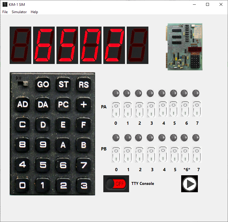
These routines also run on the KIM-1 Simulator. The non-blocking routine requires a Setting in the Simulator.
In versions before 2.3.1 check Focal-V3D, the later versions check Allow non-blocking.
The TTYdeaf routine does not work yet on the Simulator, PB5 is ignored.

Settings in 2.3.0

Settings 2.3.1