
To use a HEathkit H14 matrix printer in 1980 I have written a serial send character routine, inspired by OUTCH on Port B pin 0.
The first version was simple, like OUTCH, at low speed to let the printer have time to do its work.
The second version added RTS/CTS handshaking via a second Port B pin as input.
Both were published in the Dutch KIM Club magazine in 1980 and 1981, together with a parallel keyboard routine and integration into the MICO ADE Editor/Assembler.
Here I present the drivers, in a more general format to have a second serial output on the KIM-1 optionally with handshake.
The hardware to adapt the KIM-1 to the RS232C levels can be kept simple. Here some examples:
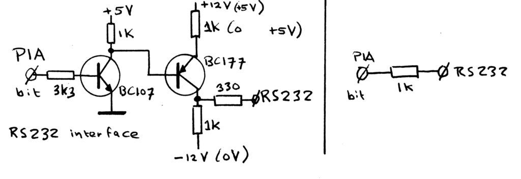
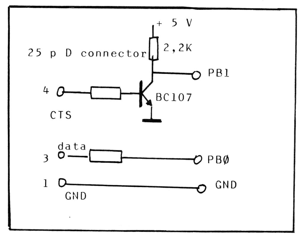
You can find the sources in TASM32 format here.
0001   0000             ;
0002   0000             ; Serial output for example to drive a printer connected to a KIM-1
0003   0000             ; 1980 Original by Hans Otten
0004   0000             ; 2026 Cleaned of MICRO ADE artefacts and converted to TASM
0005   0000             ;
0006   0000             ; Original in MICRO ADE syntax, curent version TASM32 Hans Otten, 2026
0007   0000             ;
0008   0000             ; Serial output routine (inspired by OUTCH in KIM-1 monitor)
0009   0000             ;
0010   0000             ; Send a byte in RS232C format via a PIA bit
0011   0000             ;
0012   0000             ; Choose MASK0 and MASK1 so any pin of a PIA can be ued
0013   0000             ; Choose OUT for any PIA 6520/6521/6522/6530/6820/21. A 6522 VIA needs other initialization
0014   0000             ;
0015   0000             ; The baud rate is determined by using the following table for calling delay routine
0016   0000             ; BAUD    A   Y
0017   0000             ;   75   189  10
0018   0000             ;  110    80  0A
0019   0000             ;  300    9C  03
0020   0000             ;  600    D8  01
0021   0000             ; 1200    71  01
0022   0000             ; 2400        4C
0023   0000             ; 4800        22
0024   0000             ; 9600        14
0025   0000             ;
0026   0000             ; Use the second delay routine if only one value is given, w.o.w. above 1200 baud.
0027   0000             ;
0028   0000             ; In the following driver pin PB0 of the KIM-1 is chosen as output, and a baudrate of 4800.
0029   0000             ; Adapt OUT, TI, TII, MSKO, MASKI and choose the applicable delay routine
0030   0000             ;
0031   0000             ; Serial driver without handshake via PB0 KIM-1
0032   0000             ; Original Hans Otten KIM Kenner 12
0033   0000             ;
0034   0000             ;
0035   0000             ; Zeropage used, only during sending character
0036   0000             ;
0037   0000             CHAR	= $FE
0038   0000             TEMP	= $FD
0039   0000             TMPX	= $FC
0040   0000             ;
0041   0000             MASKI	= $01				; set PB0 bit 0 of port for serial OUT
0042   0000             MASKO	= $FE				; clear PB
0043   0000             ;
0044   0000             ; Port PBO address
0045   0000             ;
0046   0000             OUT		=  $1702	; PBDD data Port B
0047   0000             OUTD	=  $1703	; PBD  data direction Port B
0048   0000
0049   0000             ;
0050   0200             		.ORG 	$0200
0051   0200             ;
0052   0200 48          OUTPR	PHA					; save character
0053   0201 84 FD       		STY		TEMP		; save Y
0054   0203 86 FC       		STX		TMPX		; save X
0055   0205 85 FE       		STA		CHAR		; save character to send
0056   0207 AD 03 17    		LDA 	OUTD		;
0057   020A 09 01       		ORA		#MASKI		;
0058   020C 8D 03 17    		STA 	OUTD		; set Port B PB0 as output
0059   020F AD 02 17    		LDA		OUT			;
0060   0212 09 01       		ORA		#MASKI		;
0061   0214 8D 02 17    		STA		OUT			;
0062   0217 20 51 02    		JSR		TDELAY		; send out startbit 1
0063   021A A2 08       		LDX		#$08		; 8N1 8 databits
0064   021C AD 02 17    NEXTB	LDA		OUT
0065   021F 46 FE       		LSR		CHAR		; lsb in carry
0066   0221 B0 04       		BCS		ONE			; bit is 1?
0067   0223 09 01       		ORA		#MASKI		;
0068   0225 90 02       		BCC		BOUT			; set bit
0069   0227 29 FE       ONE		AND		#MASKO		; bit is 0
0070   0229 8D 02 17    BOUT	STA		OUT			; set bit
0071   022C 20 51 02    		JSR		TDELAY		; wait bit time
0072   022F CA          		DEX					; next bit
0073   0230 D0 EA       		BNE		NEXTB		;
0074   0232 AD 02 17    		LDA		OUT			; stop bit
0075   0235 29 FE       		AND		#MASKO		; is zero
0076   0237 8D 02 17    		STA 	OUT
0077   023A 20 51 02    		JSR 	TDELAY
0078   023D             ;		JSR		TDELAY		; if you want 2 stop bits
0079   023D A6 FC       		LDX		TMPX		; resatore X, Y, A
0080   023F A4 FD       		LDY		TEMP
0081   0241 68          		PLA
0082   0242 60          		RTS
0083   0243
0084   0243             ;
0085   0243             ; 	Delay for 110 baud A, Y from table
0086   0243             ;
0087   0243 A0 0A       DELAY	LDY		#$0A
0088   0245 A9 80       OLOOP	LDA		#$80
0089   0247 38          ILOOP	SEC
0090   0248 E9 01       		SBC		#$01		; inner loop A*7 -1
0091   024A D0 FB       		BNE		ILOOP
0092   024C EA          		NOP
0093   024D 88          		DEY
0094   024E D0 F5       		BNE		OLOOP		;
0095   0250 60          		RTS
0096   0251
0097   0251 A0 0E       TDELAY	LDY		#14			; time = Y+5 -1
0098   0253 88          TDLOOP	DEY
0099   0254 D0 FD       		BNE 	TDLOOP
0100   0256 60          		RTS
0101   0257
0102   0257             		.END


Label        Value      Label        Value      Label        Value
------------------      ------------------      ------------------
BOUT          0229      CHAR          00FE      DELAY         0243
ILOOP         0247      MASKI         0001      MASKO         00FE
NEXTB         021C      OUT           1702      OUTD          1703
OUTPR         0200      ONE           0227      OLOOP         0245
TEMP          00FD      TMPX          00FC      TDELAY        0251
TDLOOP        0253

tasm: Number of errors = 0


0001   0000             ;
0002   0000             ; Serial output for example to drive e.g. a serial interface printer connected to a KIM-1
0003   0000             ; 1980 Original by Hans Otten
0004   0000             ; 1981 adapted to RTS CTS handshaking
0005   0000             ; 2026 Cleaned of MICRO ADE artefacts and converted to TASM
0006   0000             ;
0007   0000             ; Original in MICRO ADE syntax, curent version TASM32 Hans Otten, 2026
0008   0000             ;
0009   0000             ; Serial output routine (inspired by OUTCH in KIM-1 monitor)
0010   0000             ;
0011   0000             ; Send a byte in RS232C format via a PIA bit
0012   0000             ;
0013   0000             ; Choose MASK0 and MASK1 so any pin of a Port can be used for serial output
0014   0000             ; Chsooe MSKCTS to select a pin for input of the RTS/CTA handshake line.
0015   0000             ; Assumed both pins are on the same port.
0016   0000             ; Choose OUT for any PIA 6520/6521/6522/6530/6820/21. A 6522 VIA needs other initialization
0017   0000             ;
0018   0000             ; The baud rate is determined by using the following table for calling delay routine
0019   0000             ; BAUD    A   Y
0020   0000             ;   75   189  10
0021   0000             ;  110    80  0A
0022   0000             ;  300    9C  03
0023   0000             ;  600    D8  01
0024   0000             ; 1200    71  01
0025   0000             ; 2400        4C
0026   0000             ; 4800        22
0027   0000             ; 9600        14
0028   0000             ;
0029   0000             ; Use the second delay routine if only one value is given, w.ow above 1200 baud.
0030   0000             ;
0031   0000             ; In the following driver pin PB0 of the KIM-1 is chosen as output, and a baudrate of 4800
0032   0000             ; For RTS/CTS handling pin PB1 is used as input
0033   0000             ; Adapt OUT, TI, TII, MASKO, MASKI and MSKCTS and choose the applicable delay routine
0034   0000             ;
0035   0000             ; Serial driver with via PB0 KIM-1
0036   0000             ; Original Hans Otten PGJ de Beer KIM Kenner 19
0037   0000             ;
0038   0000             ; Zeropage used, only during sending character
0039   0000             ;
0040   0000             CHAR	= $FE
0041   0000             TEMP	= $FD
0042   0000             TMPX	= $FC
0043   0000             ;
0044   0000             MASKI	= $01				; set PB0 bit 0 of port for serial OUT
0045   0000             MASKO	= $FE				; clear PB
0046   0000             MSKCTS  = $02				; isolate RTS CTS pin, here PB1
0047   0000             MSKCTI	= $FD
0048   0000             ;
0049   0000             ; Port PBO, PB1 addresses
0050   0000             ;
0051   0000             OUT		=  $1702	; PBDD data  Port B
0052   0000             OUTD	=  $1703	; PBD  data direction Port B
0053   0000
0054   0000             ;
0055   0300             		.ORG 	$0300
0056   0300             ;
0057   0300 08          OUTPR	PHP
0058   0301 48          		PHA					; save character
0059   0302 84 FD       		STY		TEMP		; save Y
0060   0304 86 FC       		STX		TMPX		; save X
0061   0306 85 FE       		STA		CHAR		; save character to send
0062   0308 AD 03 17    		LDA 	OUTD		;
0063   030B 09 01       		ORA		#MASKI		; output pin serial
0064   030D 29 FD       		AND		#MSKCTI		; input pin RTS
0065   030F 8D 03 17    		STA 	OUTD		; set Port B PB0 as output, PB1 as input
0066   0312 AD 02 17    BUFF	LDA		OUT
0067   0315 29 02       		AND		#MSKCTS		; is RTS active?
0068   0317 F0 F9       		BEQ		BUFF		; wait
0069   0319 AD 02 17    		LDA		OUT			;
0070   031C 09 01       		ORA		#MASKI		;
0071   031E 8D 02 17    		STA		OUT			;
0072   0321 20 5B 03    		JSR		TDELAY		; send out startbit 1
0073   0324 A2 08       		LDX		#$08		; 8N1 8 databits
0074   0326 AD 02 17    NEXTB	LDA		OUT
0075   0329 46 FE       		LSR		CHAR		; lsb in carry
0076   032B B0 04       		BCS		ONE			; bit is 1?
0077   032D 09 01       		ORA		#MASKI		;
0078   032F 90 02       		BCC		BOUT			; set bit
0079   0331 29 FE       ONE		AND		#MASKO		; bit is 0
0080   0333 8D 02 17    BOUT	STA		OUT			; set bit
0081   0336 20 5B 03    		JSR		TDELAY		; wait bit time
0082   0339 CA          		DEX					; next bit
0083   033A D0 EA       		BNE		NEXTB		;
0084   033C AD 02 17    		LDA		OUT			; stop bit
0085   033F 29 FE       		AND		#MASKO		; is zero
0086   0341 8D 02 17    		STA 	OUT
0087   0344 20 5B 03    		JSR 	TDELAY
0088   0347             ;		JSR		TDELAY		; if you want 2 stop bits
0089   0347 A6 FC       		LDX		TMPX		; resatore X, Y, A
0090   0349 A4 FD       		LDY		TEMP
0091   034B 68          		PLA
0092   034C 60          		RTS
0093   034D
0094   034D             ;
0095   034D             ; 	Delay for 110 baud A, Y from table
0096   034D             ;
0097   034D A0 0A       DELAY	LDY		#$0A
0098   034F A9 80       OLOOP	LDA		#$80
0099   0351 38          ILOOP	SEC
0100   0352 E9 01       		SBC		#$01		; inner loop A*7 -1
0101   0354 D0 FB       		BNE		ILOOP
0102   0356 EA          		NOP
0103   0357 88          		DEY
0104   0358 D0 F5       		BNE		OLOOP		;
0105   035A 60          		RTS
0106   035B
0107   035B A0 0E       TDELAY	LDY		#14			; time = Y+5 -1
0108   035D 88          TDLOOP	DEY
0109   035E D0 FD       		BNE 	TDLOOP
0110   0360 60          		RTS
0111   0361
0112   0361             		.END


Label        Value      Label        Value      Label        Value
------------------      ------------------      ------------------
BUFF          0312      BOUT          0333      CHAR          00FE
DELAY         034D      ILOOP         0351      MASKI         0001
MASKO         00FE      MSKCTS        0002      MSKCTI        00FD
NEXTB         0326      OUT           1702      OUTD          1703
OUTPR         0300      ONE           0331      OLOOP         034F
TEMP          00FD      TMPX          00FC      TDELAY        035B
TDLOOP        035D

tasm: Number of errors = 0
See also:
Teach KIM to Sing
A program to let the KIM-1 play music. Store notes and its pitch in memory and listen to it.
Published in the Byte Bo...
Radio Bulletin articles in English
A collection of articles about the KIM-1, original in Dutch, here translated to English and with source and binary of th...
Replica 1 TE PAL version
User ExPLIT on the German forum Verein zum Erhalt klassischer Computer e.V.
has build an Apple 1 Replica 1 TE from th...
Jolt with 4K and power supply
With thanks to Jonathan Chapman of Glitchworks who found a Jolt system, here images of a Jolt with 4K memory, an experim...