It all started on the VCFED forum, when people were looking for help on repairing their KIM-1 computer.
So Dwight Elvey designed and programmed a diagnostic board for the KIM-1, to determine what might be wrong with this KIM-1.
The board switches off the 6530 ROMs and one can run tests on the onboard ROM, looking for for defective RAM, defective LED display, defective 6530 ports.
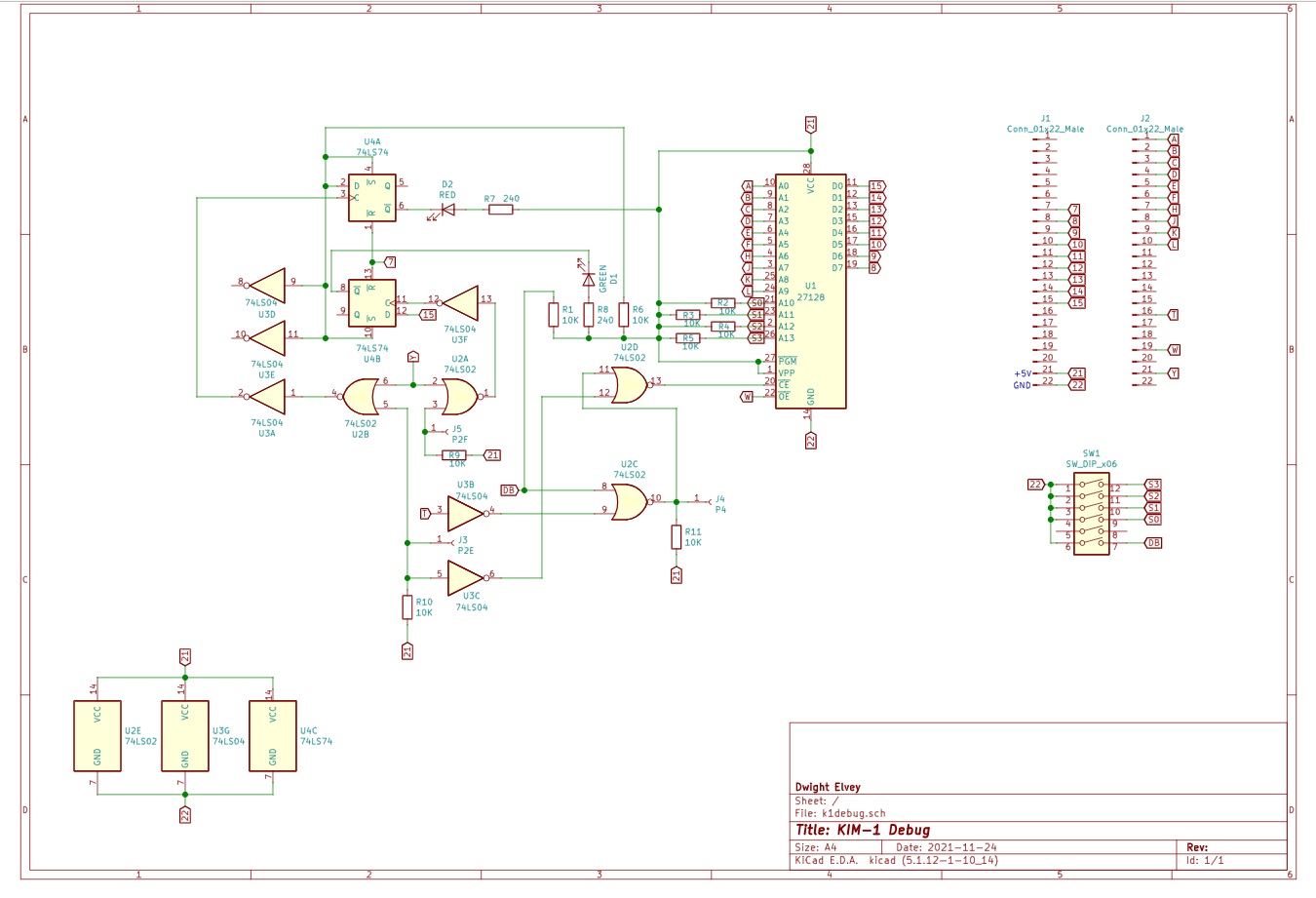
Here I present the complete design of the board, with help and permission of Dwight Elvey, Santo Nucifora and Liu Ganning.
In October 2025 I have revisited this page, build a diagnostic board myself and added the sources of the tests in MOS Technology standard assembler syntax.
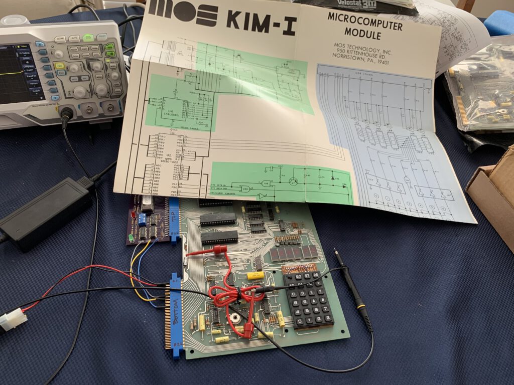
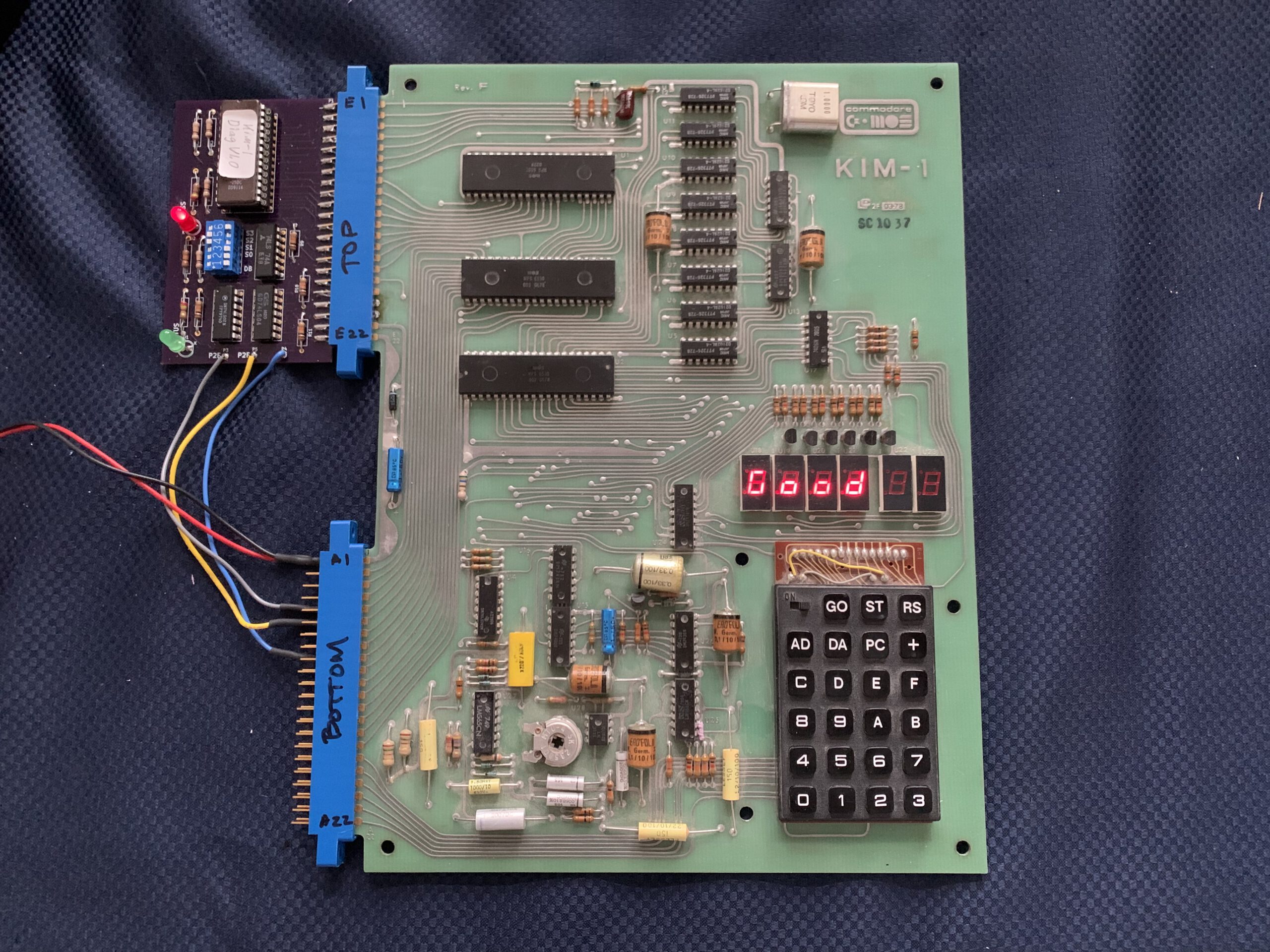
Debug board connected to a KIM-1 (Photo by Santo Nucifora)
Triggered by post on twitter by Santo Nucifora (snuci) showing the results of his tests on his impressive KIM-1 collection, I connected to Dwight Elvey for permission to publish the design files.
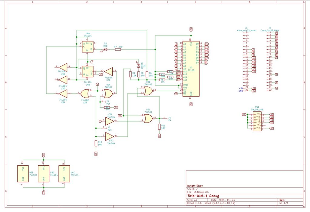
Alas, Dwight did not have the circuit diagram, only the pcb drawings and binary of the ROM.
With the aid of Santo Nucifora the instructions and sources of the debug board pack surfaced and the circuit could be reconstructed.
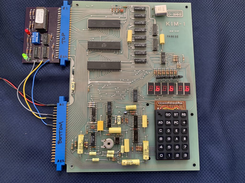
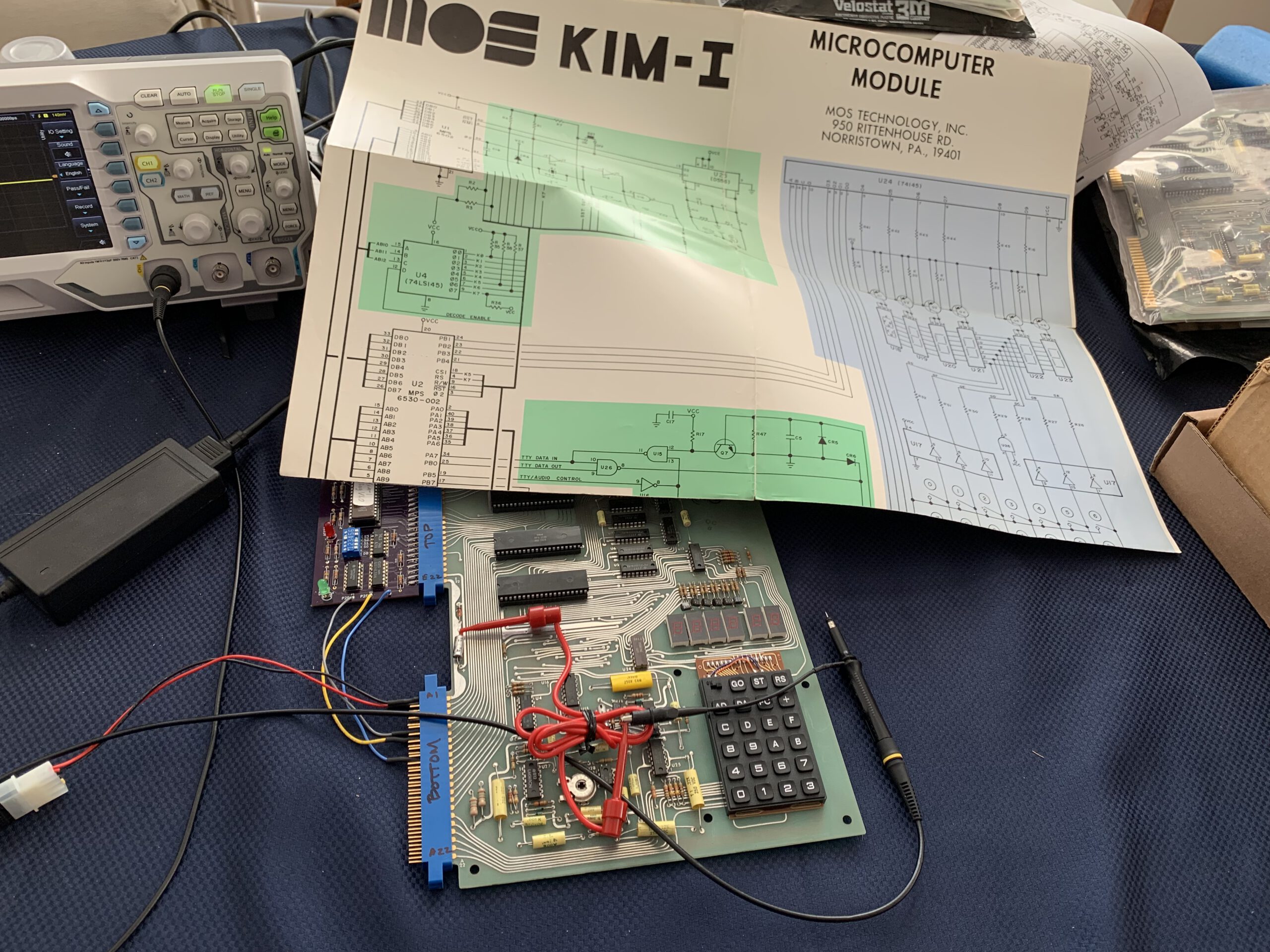
Debug board in action, defective transistors at LED display (Photo by Santo Nucifora)
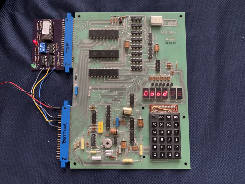
Debug board in action,KIM-1 is healthy! (Photo by Santo Nucifora)
In November 2021 Liu. the designer of the PAL-1, asked help with his defective KIM-1, it was dead. So I gave him all the information I got from Dwight and he recreated the circuit, made a PCB and started testing his kIM-1.
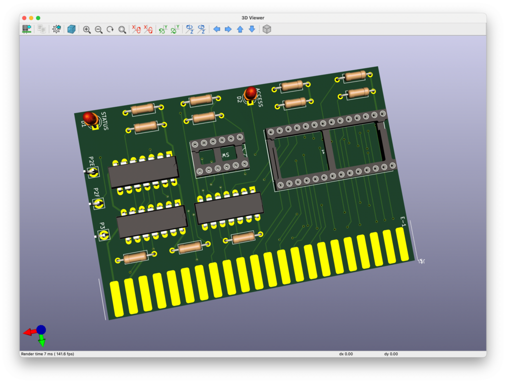
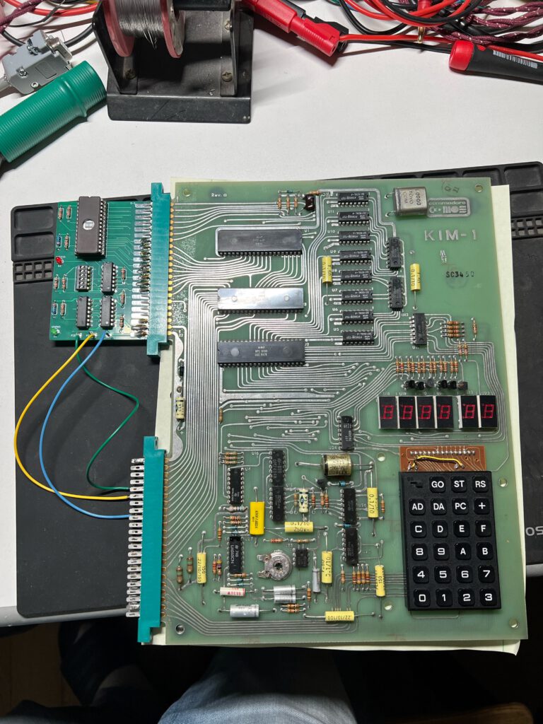
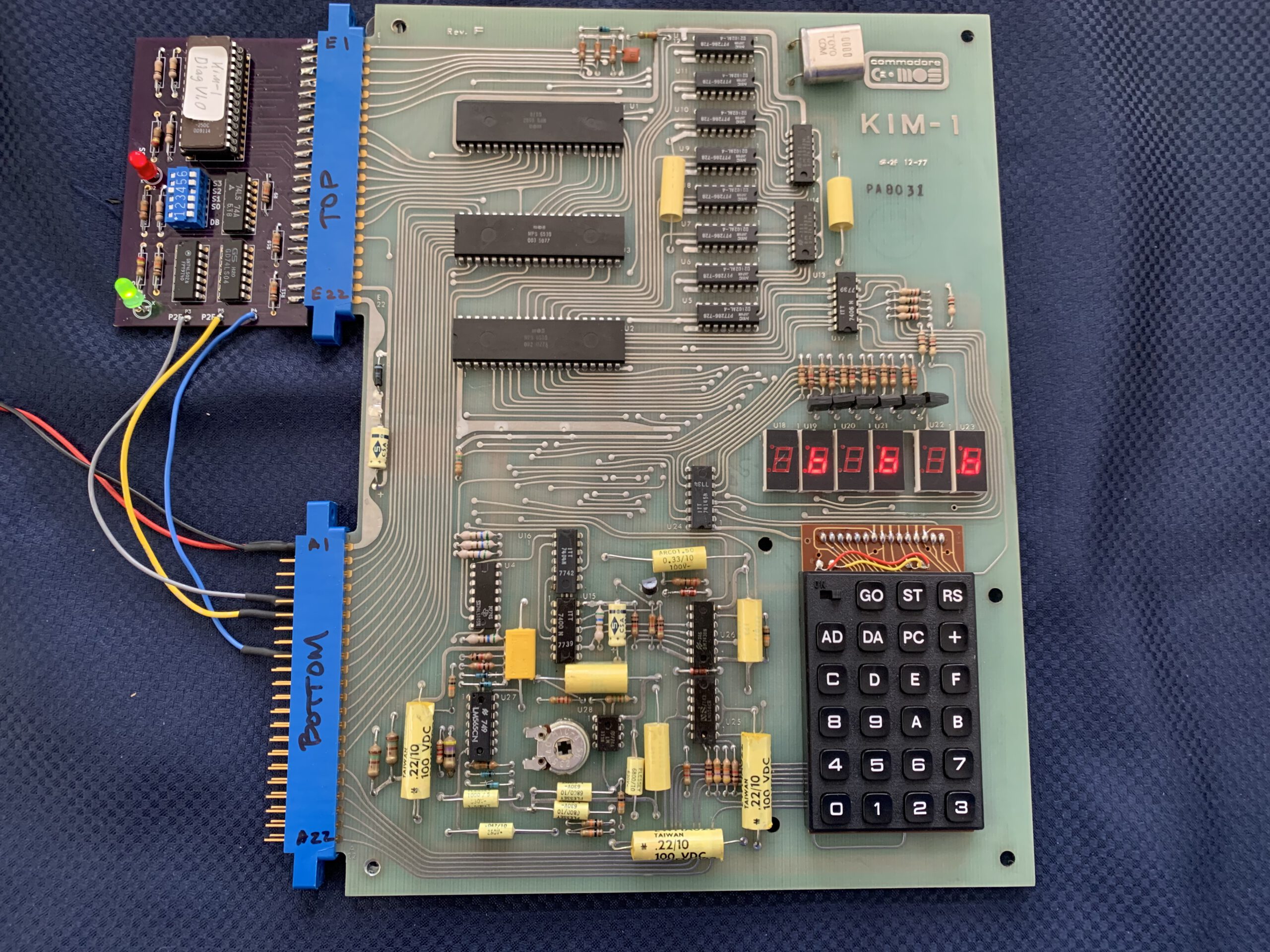
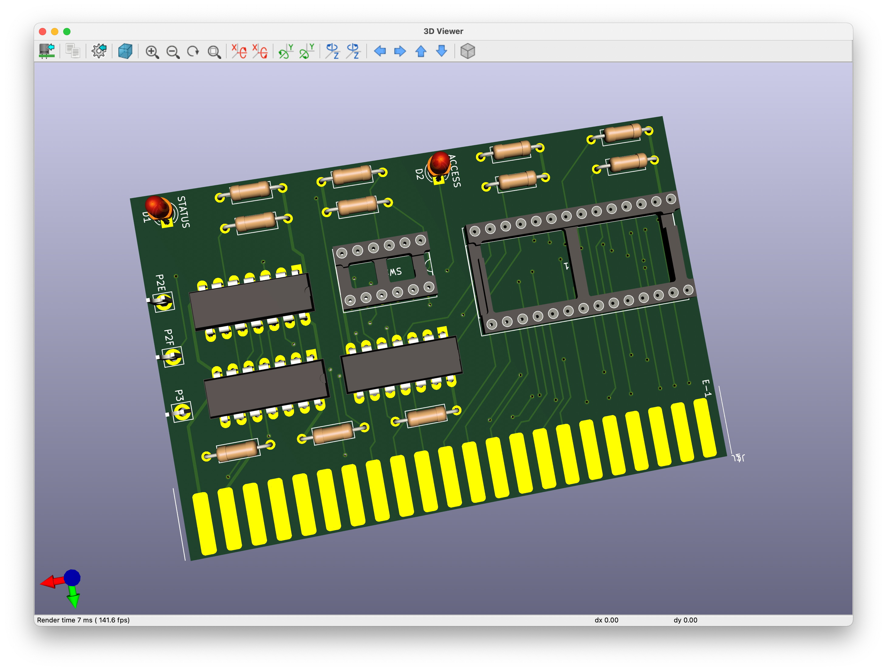
In 2025 I built a board myself:
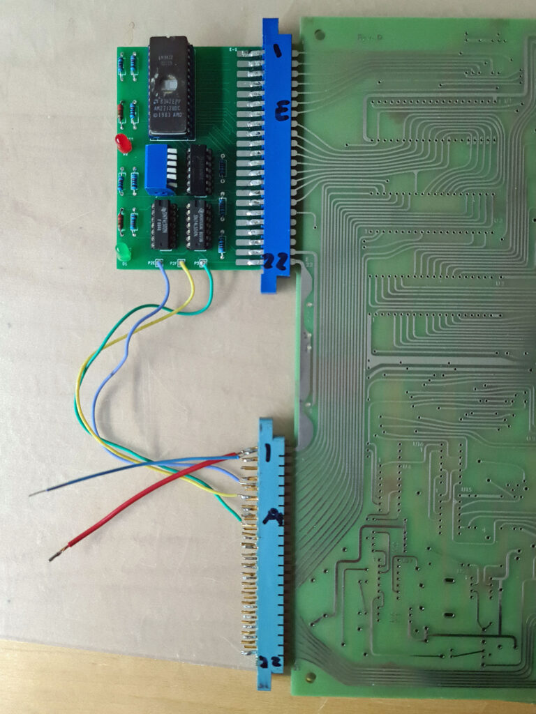
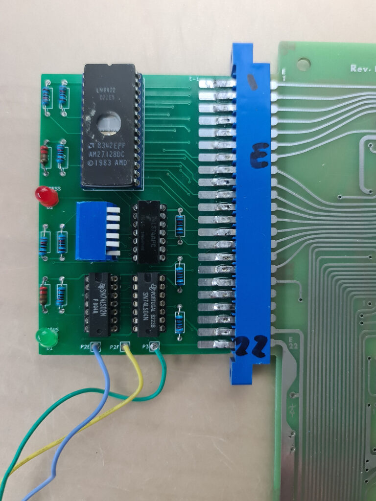
Note that my diagnostic board is connected to an at that time empty KIM-1 Replica (by Eduardo Casino).>
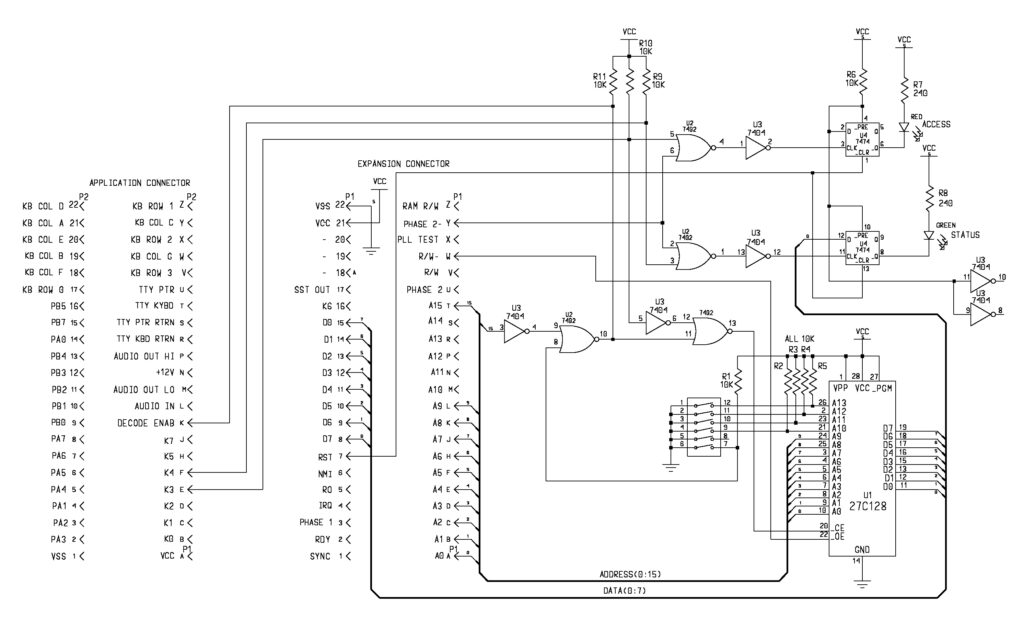
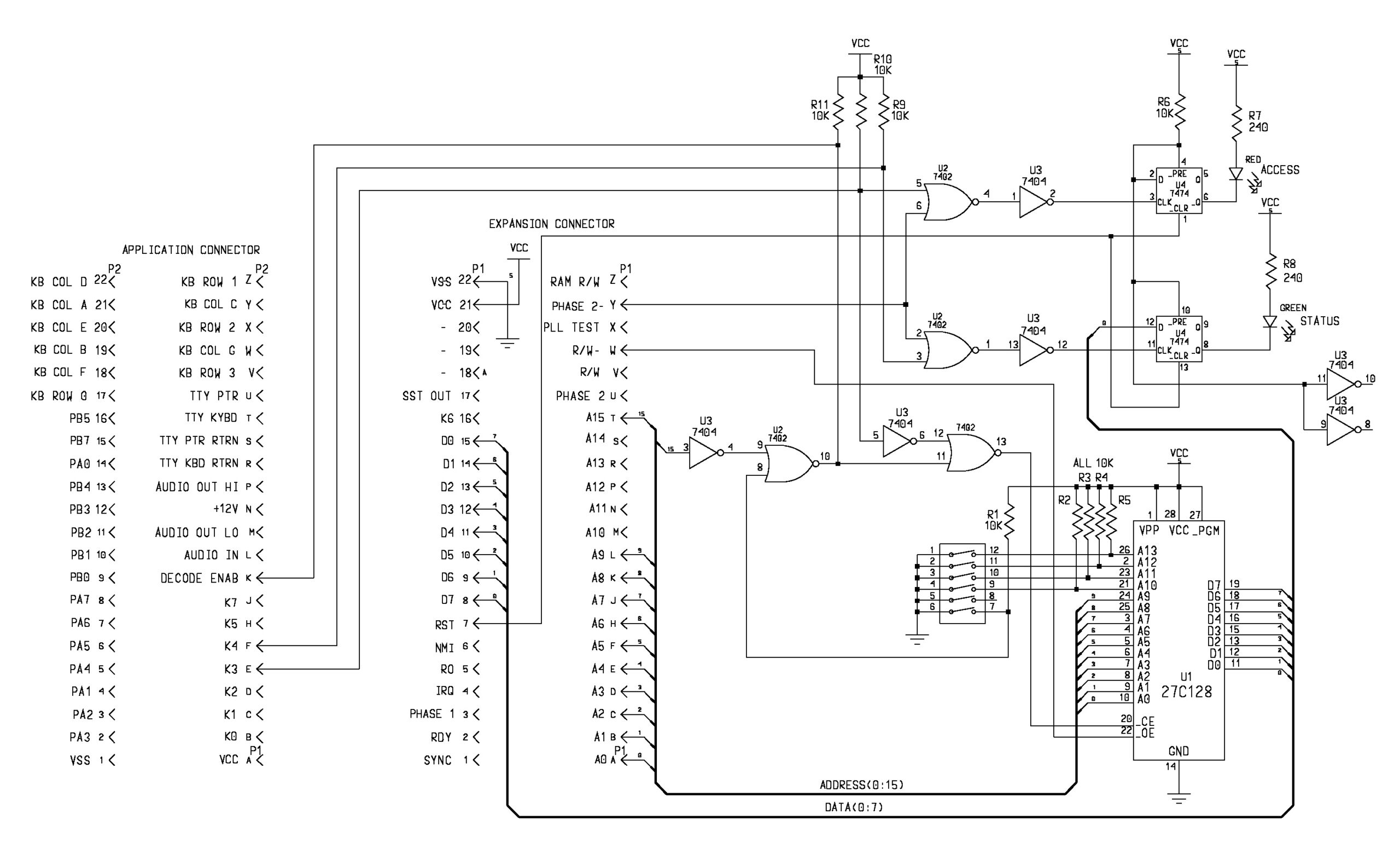
Here a redrawn and slightly modified circuit diagram by Jonathan Levine
I’ve (Dwight) been debugging my KIM-1 and while doing so, hopefully helping others. What does one do when it doesn’t work? One can check some obvious places like the clock signals, reset pulse, interrupts and sync signal. Beyond that there is little that one can do with the monitor code dead. The problem could be any of the chips, from the simplest 7404 to one of the RRIOT chips. I’ve always said that one should write code and use an EPROM to test the functions of the board. Now I’m putting actions to these words. First one needs to create a place to put an EPROM if there is no socket. That is what I did for the KIM1. I have created a small board with a minimum of parts on a prototype board.
A little about the circuit. It is designed to run with a minimal amount of the KIM computer working. The processor has to be able to execute code and access the data but and addresses. The code I’ve written also expects the KIM’s address decoder chip to be functioning. In order to work, the debug board uses both connectors for signals. The expansion connector is mostly used but three signals are needed from the application connector. You’ll need 2 44 pin connectors.
The board disables the KIM’s ROM and takes over boot. One typically the sets the reset vector to $0C00 and assembles the code there (in other words the the reset vector need to be at $0FFC as the EPROM will be seen at $0FFFC as well as $0FFC, being dual mapped. In fact the EPROM will also be mirrored at every 1K if A15=1. This can be useful if KIM’s addresses decoder doesn’t work.
There are 2 LEDs on the debug board. One LED is on if it sees a access to the 1K space at $0C00 to $0FFF. It is not a fool proof indicator but if lit generally indicates that code is executing.
It can only be reset with the reset signal ( RS on the keyboard ). The other LED is a status light. It can be turned on and off from code. A write to $1000 of the D0=1 will turn it on and a write with D0=0 will turn it off. It provides a minimal feedback until KIM’s 7 segment LEDs are found to be functional. It also is needed to verify that the 1K RAM at address 0 is functional.
The RAM is needed to be able to use the stack and any zero page address. It can also be use to just blink to make sure a long running test is still working.
Downloads
Instructions
(from file DBINSTR.TXT)
Diagnostic Debug for the KIM-1 and 6530 to 6532 adapter

The diagnostic EPROM can hold up to 16 1K diagnostic or other programs.
Most of these diagnostic programs are intended to take over reset from
the onboard ROMs in order to run various diagnostic test on the KIM-1
hardware.
The control of which to boot from is controlled by the DB switch.
With a working monitor, it can be run by opening the DB switch.
The Diagnostic Debug board is also used to initialize the EEPROM on
the 6530 to 6532 adapter with either the code for -002 or -003 ROM
data. When the switch on the Diagnostic Debug board has the DB
position turned on, the boot vevtors come from the EPROM on the
Diagnostic Debug board.
Any 1K address above 8000H will be decoded from the 1k block selected
by the switch S0 to S3. Note that the switch between DB and S0 is not
used.
These 1k blocks are always decoded from 8000H as long as the DB switch
is on. This takes over the interupt and boot vectors.
There is always a 1K block decoded at 0C00 to 0FFF as well. This is
available, even if booted from the monitors ROM, regardless of the DB
switch position.
The main thing the DB switch does is allow the boot to happen from the
Diagnostic Debug EPROM rather than from a possibly defective -002
monitor ROM.
Each 1K test block is intended be run in sequence. This allows one to
test and diagnose a single area of the KIM-1 at a time.
Many test depend on the passing of the previous test. An obvious
example is if there is a RAM failure the display test is likely to
fail as well.
A failure of a later test may not be a positive indication that the
failure is what the test is testing for if a previous test has failed.
One should diagnose and repair the earliest test first.


Test 0  Flash
 Switch setting:
  DB on
  --
  S0 on
  S1 on
  S2 on
  S3 on
  This is a minimal test of the processor. All it does
is slowly flash the Green LED on the diagnostic board.
It is initiated by the reset switch, on the keyboard of the KIM-1
( RS ).
This test only uses the processor, addresss decoder and data bus.
If it fails to run. It will be a problem in one of these areas.
This test does not use any of the RAM in either the 2102s or in
either of the 6530 RAM areas. It only uses a few instructions and
is not a complete CPU diagnostic.
Remember the processor includes clocks and reset vector and possible
MNI stuck.
As a bonous some of the extra space has the program Astroids from the
First Book of Kim. It the normal KIM-1 monitor is running, one can
play if by setting the same switches as Flash except DB to off.
set the address at 0E00 and GO.
Use 0 and 3 to move your space ship to avoid the astroids.

Test 1  RAMTEST
 Switch setting:
  DB on
  --
  S0 off
  S1 on
  S2 on
  S3 on
 This test does a simple stuck at test of the RAM by writing and
reading 055H and 0FFH to each location in the 2102 RAM array.
A passing indication is that the Green LED will blink at about 1
seconds rate for 8 time then on the 9th it will stay lit.
Should there be a failure the Green LED will blink out the failing
bit number. A 1 second blink indicates a good bit and a short blink
indicates a failed bit. After the 8th blink it will stay unlit.
If all the bits fail it may be an address decoder problem.
A single bit failure is likely a single RAM or the bus buffer.
The blink code starts with bit D0 and blinks through to D7.
This test does not test or use the 6530/2 RAM for vaiables during the
test, other than the RAM it test. It only runs
in the processor's internal registers. This is not easy to do
for a 6502. This is the reason it doesn't also indicate the failed
address as well as the bit. This would likely need the variable space
that is under test.
Once this test passes, later test will assume that the RAM
on Page0 and Page1 are functional and use them as most 6502 programs
do.
There are still possible address errors that RAMs can have.
This test is initiated by the RS reset button on the keyboard.
As an example, a long-long-short-long-long-long-long-long
blink code would indicat that bit D2 was failing. In other
words the blink code is D0 first to D7 last. With the board
such that the key board is on the lower right, the RAM
chips blink from top to bottom for the blink codes. Each blink is
one RAM chip position.

Test 2  Display
 Switch setting:
  DB on
  --
  S0 on
  S1 off
  S2 on
  S3 on
This test the displays. It will also flash the green LED just in case
the display isn't working so that you know that the test is running.
It sequences 0000 00 to FFFF FF. Not much else to say here.

Test 3 KeyBd
 Switch setting:
  DB on
  --
  S0 off
  S1 off
  S2 on
  S3 on
This is used to test the keyboard. It test all the buttons.
Pressing RS will restart the test. ST will light the green
light ( use RS to turn it off if you like ).
The other keys will display the row and column for each button.
Refer to the schematic for a reference.
As an example, the E button will display 2 G.
Try each switch from 0 to GO to see what unique combination
is created. This test is run with the small, on/off, switch
on the keyboard in the OFF position.
This switch can be tested by using the single step function
as described in the KIM-1 Users manual, with the normal KIM-1
monitor.

Key table:
   ROW  COL
0   0    G
1   0    F
2   0    E
3   0    d
4   0    c
5   0    b
6   0    A
7   1    G
8   1    F
9   1    E
A   1    d
B   1    c
C   1    b
D   1    A
E   2    G
f   2    F
AD  2    E
DA  2    d
PC  2    A
+   2    c
GO  2    b

Test 4 CRC2
 Switch setting:
  DB on
  --
  S0 on
  S1 on
  S2 off
  S3 on
This test the ROM data for -002. It will flash the CRC generated
from reading the entire ROM. It should read C219. It does this
in a continuous loop. That is why the display flashes, because
it is rerunning the CRC code and not updating the display.
Any erratic value could be an indication of ROM failue.

Test 5 CRC3
 Switch setting:
  DB on
  --
  S0 off
  S1 on
  S2 off
  S3 on
This test the ROM data for -003. It is the same as CRC2 but the
CRC numbers are 5EA4 instead, for the -003 chip.

Test 6 64RAM2
 Switch setting:
  DB on
  --
  S0 on
  S1 off
  S2 off
  S3 on
This test the 64 bits of RAM in the -002 6530 chip. It uses the
March C algorythm. This is a very good test. If it passes, it says
'Good'. If it fails it says 'Bad nn' Where the nn indicates the
bad address. Say it displayed Bad C9'. That would indicate that the
address 1700 + C9 = 17C9 failed. Make sure to start the test from a
clean reset by pushing the RS when changing the debug switches or
when powering up.

Test 7 64RAM3
 Switch setting:
  DB on
  --
  S0 off
  S1 off
  S2 off
  S3 on
This test the 64 bits of RAM in the -003 6530 chip. It uses the
March C algorythm. This is a good test. If it passes, it says
'Good'. If it fails it says 'Bad nn' Where the nn indicates the
bad address. Say it displayed 'Bad 92'. That would indicate thath the
address 1700 + 92 = 1792 failed. Make sure to start the test from a
clean reset by pushing the RS when changing the debug switches or
when powering up.

Test 8 EEPROM2
  DB on
  --
  S0 on
  S1 on
  S2 on
  S3 off
This is not really a test. This is code to program the EEPROM on
the -002 adapter module. The EEPROM on the adapter is not programmed.
this must be done on the KIM-1 by this program.
Install the adpater observing the proper orientation with the KIM
powered off.
The yellow jumper is for the -002 decode. It must be intact. The red
jumper enables EEPROM programming.
Set the switches as above and hit the RS button then power up.
This loads the programming code into RAM. Make sure to
do a clean reset (RS) after setting up the switches for this code.
The programming code is loaded into RAM in a millisecond or so. The
only indication is that the RED LED will be lit.
The image for the EEPROM is a full 1024 bytes and the diagnosic code
window in memory is only 1024 bytes. It is not possible to have the
programming code and the ROM image in the same debug switch settings.
Once the code is in RAM, it waits for you to select the ROM image
by the debug switch settings.
You do this by changing the Debug switches to:
  DB on
  --
  S0 off
  S1 on
  S2 on
  S3 off
Make sure the upper left keyboard switch is in the off position.
Now press the ST button. This causes a NMI interrupt that starts
the programming cycle.
The green light should flash quickly. This indicated that the programming
is continuing OK.
If the Green LED then goes off, the programming is complete.
If the Green LED comes on steady, the programming has failed.
It would be wise to test that the EEPROM is working. Hold the RS
button down and set the DB to off. Releasing the RS should start the
normal KIM-1 monitor( it usually requires the AD or some switch
selected to determine user input source.
If it is working, it is wise to now cut the red wire loop at the end
of the adapter board ( only the red wire the other is -002/-003 select ).
This blocks the accidental writes to the EEPROM. I recommend leaving
a little wire as you might want to change the programming at some
future time.

Test 10 EEPROM3
  DB on
  --
  S0 on
  S1 off
  S2 on
  S3 off
This is not really a test. This is code to program the EEPROM on
the -003 adapter module. The EEPROM on the adapter is not programmed.
this must be done on the KIM-1 by this program.
Install the adpater observing the proper orientation with the KIM
powered off.
The yellow jumper is part of the decode for -003. The yellow jumper
must be cut for -003 location. The red jumper enables programming.
Set the switches as above and hit the RS button then power up.
This loads the programming code into RAM. Make sure to
do a clean reset (RS) after setting up the switches for this code.
The programming code is loaded into RAM in a millisecond or so. The
only indication is that the RED LED will be lit.
The image for the EEPROM is a full 1024 bytes and the diagnosic code
window in memory is only 1024 bytes. It is not possible to have the
programming code and the ROM image in the same debug switch settings.
Once the code is in RAM, it waits for you to select the ROM image
by the debug switch settings.
You do this by changing the Debug switches to:
  DB on
  --
  S0 off
  S1 off
  S2 on
  S3 off
Make sure the upper left keyboard switch is in the off position.
Now press the ST button. This causes a NMI interrupt that starts
the programming cycle.
The green light should flash quickly. This indicated that the programming
is continuing OK.
If the Green LED then goes off, the programming is complete.
If the Green LED comes on steady, the programming has failed.
It would be wise to test that the EEPROM is working.
You might run CRC3, Test 5 to verify or check the values
through the KIM-1 monitor.
It is wise to now cut the red wire loop at the end of the adapter board.
This blocks the accidental writes to the EEPROM. I recommend leaving
a little wire as you might want to change the programming at some
future time.
-003 EEPROM code has a large blank portion of code space near the
end. You might want to want some special code that is always resident
that you could put it this space. It is starting at 1A96 and ending
at 1BF9. This is 356 bytes for a small perminent piece of code.
Of course any change to the -003 EEPROM will also change the CRC3
results. It is wise to write it down to ensure it you still have
a -003 valid test.

This is all the test in Debug EPROM. The remaining switch locations
are available for other use. If you want the KIM-1 to boot to this
code make sure to put the reset vector at the end of the 1K block.
With the DB swith to the on position and a RS reset, it will run
the EPROM code. It can be run at 0C00 to 0FFF or at FC00 to FFFF.
If the DB switch is off, code on the EPROM must be started from
the KIM-1 monitor. It will only be seen at 0C00 to 0FFF and is
not seen in the upper memory window as it would be to boot to
the debug code.
There are 4 completely unused 1K blocks left in the debug EPROM. Also
if you look at each of the test, you'll note that most of the test only
use a small portion of the 1k block. One can always add one's code
in one of these blank areas. Just remember that the code will be
offset into the 1K window starting at 0C00.
Before adding of edition the debug EPROM, make sure to make a copy
of the original EPROM.
The unused bytes, of the debug 1K blocks are all 00s so the entire
EPROM would need to be erased and editied in an external image of
the EPROM before writng an new code.
The unused 4 1K block are 0FF and can be programed without erasing
the EPROM.


 Hobbycomputer 2