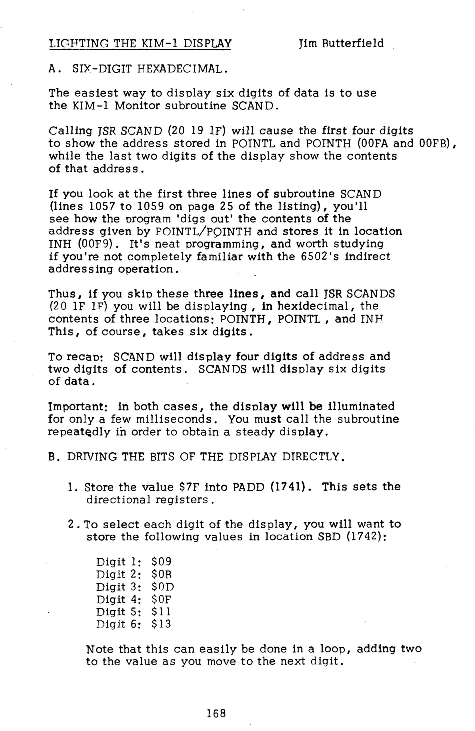
Routines to light LED display and checking for a key pressed by multiplexing the seven segment LED and checking if a key is pressed. Must be called in a loop, since the lighting is only for a short time.
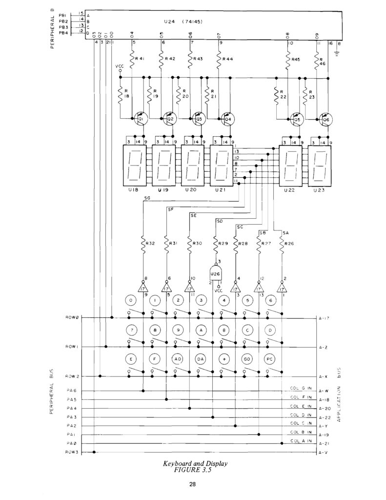
This complex looking circuit is the magic that makes the LED Display and keyboard work.
Actually this is made up of two circuits: the multiplexed LED display and the keyboard matrix.
The multiplexed LED display
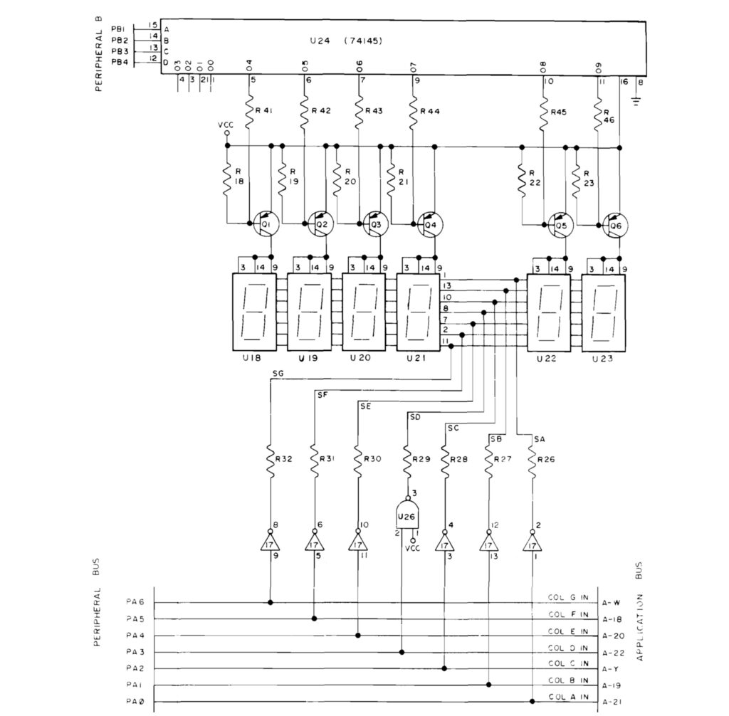
By multiplexing the lighting of the seven segment LED displays not much special hardware is required to have a hex keypad and 6 digit serviced.
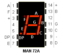
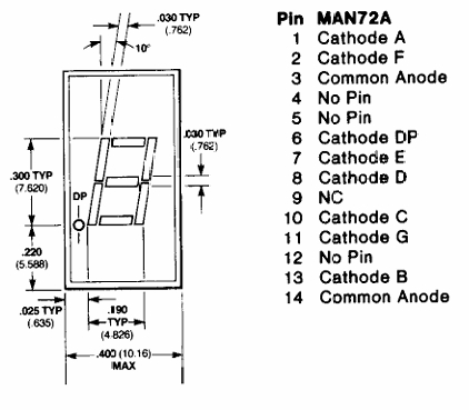
All LED displays have the segment inputs connected to each other and Port A PA0-PA6 as output are connected to the led segments a-g, PA0 = a .. PA6 = g.
The 74145 outputs O4..)9 are connected to the cathodes of the corresponding LED display.
So by setting the PB1..PB4 inputs of the 74145 one LED display is lighted, the others are off. By lighting this for a small delay and then stepping to the next display all LEDs are lighted after each other. If this is done fast enough the slow human eyes will not see this as a flickering light.
This is what is happening in the SCAND(1) routine.
Reading the keyboard matrix
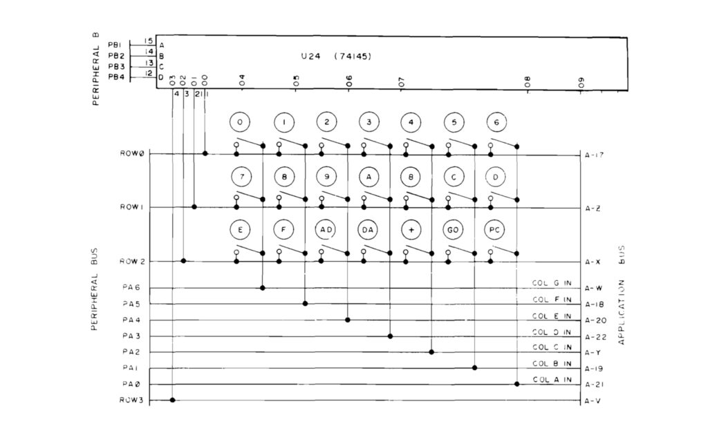
The keyboard matrix is also read out by multiplexing rows and columns checking for a short circuit if a key is pressed, via
PA0..6 as inputs and the outputs of the 74145 00-03.
By selecting row 0 to 3 (output 00 to 03 of the 74145) and reading PA0 to PA6 a pressed key is detected.
In the GETKEY routine a key is detected this way, debounced and converted to a key number 00.14.
PB1-4 to 74145 decoder
The 74145 serves the multiplexing. From the RRIOT Port B PB1 .. PB4 to A..D inputs decodes to 10 outputs 00..09.
00 – 03 Keyboard KB Row 0-3
04 – O9 outputs switch LED display 1..6 on/off one by one.
Also available on the Application connector!
Part of the keypad is the TTY/KB switch, connected via Application connector 21-V = PA0 to O3 KB Row 3 connected via switch/jumper
1030   1EFE             ;
1031   1EFE             ;       SUB TO DETERMINE IF KEY IS
1032   1EFE             ;       DEPRESSED OR CONDITION OF SSW
1033   1EFE             ;            KEY NOT DEP OR TTY MODE     A=0
1034   1EFE             ;            KEY DEP OR KB MODE      A NOT ZERO
1035   1EFE             ;
1036   1EFE             ;
1037   1EFE A0 03       AK      LDY   #$03       ;  3 ROWS
1038   1F00 A2 01               LDX   #$01       ; DIGIT 0
1039   1F02             ;
1040   1F02 A9 FF       ONEKEY  LDA   #$FF
1041   1F04 8E 42 17    AK1     STX   SBD        ;  OUTPUT DIGIT
1042   1F07 E8                  INX              ;  GET NEXT DIGIT
1043   1F08 E8                  INX
1044   1F09 2D 40 17            AND   SAD        ; INPUT SEGMENTS
1045   1F0C 88                  DEY
1046   1F0D D0 F5               BNE   AK1
1047   1F0F
1048   1F0F A0 07               LDY   #$07
1049   1F11 8C 42 17            STY   SBD
1050   1F14             ;
1051   1F14 09 80               ORA   #$80
1052   1F16 49 FF               EOR   #$FF
1053   1F18 60                  RTS
What is happening here?
- Three rows, start with first digit 0 (1037-1040)
- Select digit by setting 74145 to O(X) via PB1-4 (1041)
- Check if key pressed, A <> 0 (1044)
- next row until all rows done (1045-1046
- restore default PB1 and PB2 1, PB3, PB4 0: Os low
- return
A=0 if key not depressed or TTY mode
A<>0 if key depressed or KB mod
SCAND
show digits for a short time form current cell address and contents
1054   1F19             ;
1055   1F19             ;       SUB OUTPUT TO 7-SEGMENT DISPLAY **
1056   1F19             ;
1057   1F19 A0 00       SCAND   LDY   #$00       ; GET DATA SPECIFIED
1058   1F1B B1 FA               LDA   (POINTL),Y ; BY POINT
1059   1F1D 85 F9               STA   INH        ; SET UP DISPLAY BUFFER
1060   1F1F A9 7F               LDA   #$7F       ; CHANGE SEG
1061   1F21 8D 41 17            STA   PADD       ; TO OUTPUT
1062   1F24             ;
1063   1F24 A2 09               LDX   #$09       ; INIT DIGIT NUMBER
1064   1F26 A0 03               LDY   #$03       ; OUTPUT 3 BYTES
1065   1F28             ;
1066   1F28 B9 F8 00    SCAND1  LDA   INL,Y      ; GET BYTE
1067   1F2B 4A                  LSR   A          ; GET MSD
1068   1F2C 4A                  LSR   A
1069   1F2D 4A                  LSR   A
1070   1F2E 4A                  LSR   A
1071   1F2F 20 48 1F            JSR   CONVD      ; OUTPUT CHAR
1072   1F32 B9 F8 00            LDA   INL,Y      ; GET BYTE AGAIN
1073   1F35 29 0F               AND   #$0F       ; GET LSD
1074   1F37 20 48 1F            JSR   CONVD      ; OUTPUT CHAR
1075   1F3A 88                  DEY              ; SET UP FOR NEXT BYTE
1076   1F3B D0 EB               BNE   SCAND1
1077   1F3D 8E 42 17            STX   SBD        ; ALL DIGITS OFF
1078   1F40 A9 00               LDA   #$00       ; CHANGE SEGMENT
1079   1F42 8D 41 17            STA   PADD       ; TO INPUTS
1080   1F45 4C FE 1E            JMP   AK         ; GET ANY KEY
SCAND display four digits of address and two digits of content.
3 bytes from F9..FA are converted to hex on the six digits.
What is happening here?
- load current cell FA, FB to display buffer INH (1057..1058)
- X = 9 is selection of digit number PB1..PB4 (04..09 of 74145)
- Y = 3, number of bytes
- load low part of byte (1066..1070)
- display via CONVD (1071)
- load high part of bye
- display via CONVD (1074)
- do next byte (1075..1076)
- set all displays off PB1..PB4= 0 (1077)
- PA0..PA6 to inputs (1078..1079)
- return via AK (1080)
CONVD
Lights segment of current select digit for a short time.
Segments output via PA0..PA6.
Hex to segment conversion via TABLE lookup
Digit value in Y
X is digit number in PB1..PB4 format
1081   1F48             ;
1082   1F48             ;       CONVERT AND DISPLAY HEX
1083   1F48             ;       USED BY SCAND ONLY
1084   1F48             ;
1085   1F48 84 FC       CONVD   STY   TEMP       ; SAVE Y
1086   1F4A A8                  TAY              ; USE CHAR AS INDEX
1087   1F4B B9 E7 1F            LDA   TABLE,Y    ; LOOKUP CONVERSION
1088   1F4E A0 00               LDY   #$00       ; TURN OFF SEGMENTS
1089   1F50 8C 40 17            STY   SAD
1090   1F53 8E 42 17            STX   SBD        ; OUTPUT DIGIT ENABLE
1091   1F56 8D 40 17            STA   SAD        ; OUT PUT SEGMENTS
1092   1F59
1093   1F59 A0 7F               LDY   #$7F       ; DELAY 500 CYCLES APPROX.
1094   1F5B 88          CONVD1  DEY
1095   1F5C D0 FD               BNE   CONVD1
1096   1F5E             	;
1097   1F5E E8                  INX              ; GET NEXT DIGIT NUM
1098   1F5F E8                  INX              ; ADD 2
1099   1F60 A4 FC               LDY TEMP  ; RESTORE Y
1100   1F62 60                  RTS
What is happening here?
- convert hex to segment via TABLE lookup (1086 .. 1087)
- turn off all segments PA0..PA6 (1088..1089)
- enable digit via SBD = X (1090)
- light segment via SAD = A, keep PA7 to 1 (1091)
- delay some time (1093..1095
- X = next display 2 hex per hex byte (1097)
[/code]
GETKEY
Get key pressed:
– Key pressed: A is key number
– No key: A = 15
Key values are:
0..9 = $00 ..$09
AD = $10 address mode
DA = $11 data mode
+ = $12 step
GO = $13 GO execute
PC = $14 PC mode
1108   1F6A             ;
1109   1F6A             ;       GET KEY FROM KEY BOARD
1110   1F6A             ;       RETURN WITH A=KEY VALUE
1111   1F6A             ;       A GT. 15 TEHN ILLEGAL OR NO KEY
1112   1F6A             ;
1113   1F6A             ;
1114   1F6A A2 21       GETKEY  LDX   #$21       ; START AT DIGIT 0
1115   1F6C A0 01       GETKE5  LDY   #$01       ; GET 1 ROW
1116   1F6E 20 02 1F            JSR   ONEKEY
1117   1F71 D0 07               BNE   KEYIN      ; A=0 NO KEY
1118   1F73 E0 27               CPX   #$27       ; TEST FOR DIGIT 2
1119   1F75 D0 F5               BNE   GETKE5
1120   1F77 A9 15               LDA   #$15       ; 15=NOKEY
1121   1F79 60                  RTS

; key pressed

1122   1F7A A0 FF       KEYIN   LDY   #$FF
1123   1F7C 0A          KEYIN1  ASL   A          ; SHIFT LEFT
1124   1F7D B0 03               BCS   KEYIN2     ; UNTIL Y=KEY NUM
1125   1F7F C8                  INY
1126   1F80 10 FA               BPL   KEYIN1
1127   1F82 8A          KEYIN2  TXA
1128   1F83 29 0F               AND   #$0F       ; MASK MSD
1129   1F85 4A                  LSR   A          ; DIVIDE BY 2
1130   1F86 AA                  TAX
1131   1F87 98                  TYA
1132   1F88 10 03               BPL   KEYIN4
1133   1F8A 18          KEYIN3  CLC
1134   1F8B 69 07               ADC   #$07       ; MULT (X-1) TIMES A
1135   1F8D CA          KEYIN4  DEX
1136   1F8E D0 FA               BNE   KEYIN3
1137   1F90 60                  RTS
1138   1F91             ;
What is happening here?
- check if key pressed (1114..1119)
- return with $15 if none (1120)
- calculate key number 00..14 from position in matrix (1122..1136)
TABLE
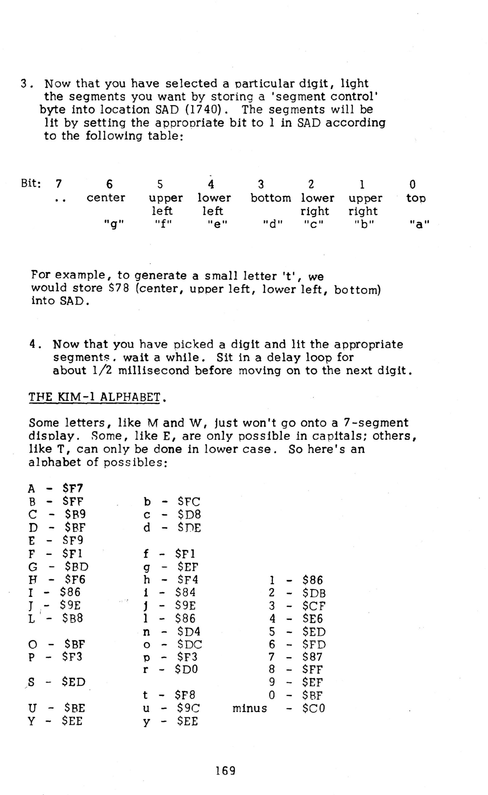
HEX to 7 segment lookup table, HEX number 0..F to segment a..g
bit 0 = a
bit 1 = b
bit 2 = c
bit 3 = d
bit 4 = e
bit 5 = f
bit 6 = g
bit 7 = 1 to keep PA7, the TTY output to 1
Seven segment layout
   a
  ---
f| g  | b
  ---
e|    | c
  ---
   d

Examples
hex 0 is all 1 except g:    1011 1111 = $BF
hex A is all 1 except d:    1111 0111 = $F7
hex F is all 1 except b,c,d 1111 0001 = $F1
1200   1FE7             ;       TABLE HEX TO 7 SEGMENT
1201   1FE7             ;              0   1   2   3   4   5   6   7
1202   1FE7 BF 86 DB CF TABLE   .BYTE  $BF,$86,$DB,$CF,$E6,$ED,$FD,$87
1202   1FEB E6 ED FD 87
1203   1FEF             ;              8   9   A   B   C   D   E   F
1204   1FEF FF EF F7 FC         .BYTE  $FF,$EF,$F7,$FC,$B9,$DE,$F9,$F1
1204   1FF3 B9 DE F9 F1
1205   1FF7             ;
The following two pages from the First Book of KIM are also interesting to see what is happening here and how to expand the routine with a larger amount of characters to show on the display.