
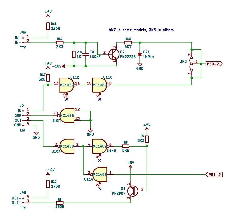
The serial interface uses two pins of Port B. PB0 is serial output, PB1 serial input. THe srial signals are handled via bitbanging and the baudrate is determined at startup.
The hardware part of the Jolt has two options, selectable with jumpers:
- 20 mA current loop.
Build with transistors and the resistors 220/270 to create the current loop. - RS232C serial interface
Classical solution with the line drivers 1488/1489.
Note that when using a TTL USB requires to invert the signals. You can tap the output from pin U11D, for the input you need an inverter (a spare 7404 will do) to connect to PB1
Routines RDT and WRT are for receiving and sending characters via the serial interface PB0 and PB1, bit-banged.
RDT echoes every character received as it comes in, bit for bit.
Determine baud rate at startup
0157   701C CA                 DEX             ; X=FF
0158   701D 9A                 TXS             ; SP=FF
0160   701E             ;                      ; COMPUTE BIT-TIME CONSTANT, X=FF
0161   701E             ;
0162   701E A0 01              LDY #1          ; SET TO MEASURE 2 BITS
0163   7020 84 E3              STY CRDLY       ;INIT OR DELAY TIME PARAMETER
0164   7022 AD 02 6E    R0     LDA MPB         ; WAIT FOR START
0165   7025 4A                 LSR A
0166   7026 90 FA              BCC R0
0167   7028             ;
0168   7028 8E 04 6E    R2     STX MCLKIT      ; START CLOCK INITIALLY WITH FF
0169   702B AD 05 6E    R3     LDA MCLKIF
0170   702E 10 04              BPL R4
0171   7030 E6 EA              INC MAJORT      ; COUNT MAJOR T
0172   7032 D0 F4              BNE R2          ; GO RESTART CLOCK WITH X = FF
0173   7034             ;
0174   7034 98          R4     TYA
0175   7035 4D 02 6E           EOR MPB
0176   7038 29 01              AND #1
0177   703A F0 EF              BEQ R3          ; WAIT FOR Y BIT 0 AND SERIAL-IN NOT EQU
0178   703C 88                 DEY
0179   703D 10 EC              BPL R3          ; LOOP UNTIL START OF BIT 2
0180   703F             ;
0181   703F AD 04 6E           LDA MCLKRD
0182   7042 49 FF              EOR #$FF        ; COMPLEMENT RESIDUE
0183   7044 4A          R5     LSR A           ; HALF IT
0184   7045 46 EA              LSR MAJORT      ; HALF MAJOR
0185   7047 90 02              BCC R6
0186   7049 09 80              ORA #$80        ; PROPAGETE HC TO LC
0187   704B C8          R6     INY
0188   704C F0 F6              BEQ R5
0189   704E 85 EB              STA MINORT
What is happening here?
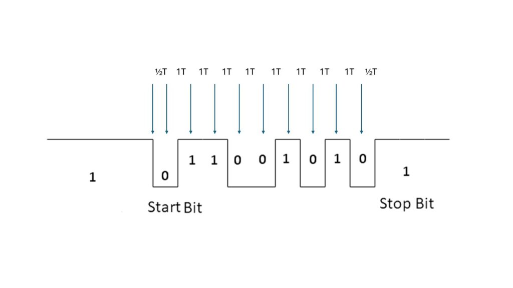
After RESET the baudrate is determined by measuring the length of the start bit of an incoming serial character. This means any character is usable where the first data bit is the opposite of the start bit (0). The TIM manual suggests using Carriage Return, which has the odd value 13, the lsb is 1 . SPACE ($20 0010 0000) for example does not work, any character with an odd value is OK.
The goal of this piece of code is to establish two variables: MAJORT and MINORT.
- The routine is entered with X = FF due to the stack pointer initialization
- The delay is measured by using the CLKIT Timer of the RRIOT filled with FF (174-179)
- MINORT is the value to let the timer run
- MAJORT is the number to repeat the timer
- the exact timer value is corrected (181-189)
Delay half and whole bit time serial as determined at startup
0634   731D             ;
0635   731D 20 20 73    DLY2   JSR DLY1
0636   7320 48          DLY1   PHA               ; SAVE FLAGS AND A
0637   7321 08                 PHP
0638   7322 8A                 TXA               ; SAVE X
0639   7323 48                 PHA
0640   7324 A6 EA              LDX MAJORT
0641   7326 A5 EB              LDA MINORT
0642   7328             ;
0643   7328 8D 04 6E    DL2    STA MCLKIT
0644   732B             ;
0645   732B AD 05 6E    DL3    LDA MCLKIF
0646   732E 10 FB              BPL DL3
0647   7330 CA                 DEX
0648   7331 08                 PHP
0649   7332 AD 04 6E           LDA MCLKRD        ; RESET TIMER INT FLAG
0650   7335 28                 PLP
0651   7336 10 F3              BPL DL3
0652   7338             ;
0653   7338 68                 PLA               ; RESTORE REGS
0654   7339 AA                 TAX
0655   733A 28                 PLP
0656   733B 68                 PLA
0657   733C 60          DLX    RTS
What is happening here?
- DLY2 waits one bit time (635).
- DLY1 is used to wait one half bit time, as determined at startup.
- Registers are saved (636-639)
- The timer is run with value MINORT for MAJORT times (640-651)
WRT WROC Write character to serial interface
0572   72C6             ;
0573   72C6             ;  WRITE SERIAL OUTPUT
0574   72C6             ;  A = CHAR TO BE OUTPUT
0575   72C6             ;
0576   72C6 20 1D 73    WRT    JSR DLY2
0577   72C9 A2 09              LDX #9
0578   72CB             WROC   =WRT
0579   72CB 49 FF              EOR #$FF          ; COMPLEMENT A
0580   72CD 38                 SEC
0581   72CE             ;
0582   72CE 20 DA 72    WRT1   JSR OUT
0583   72D1 20 1D 73           JSR DLY2
0584   72D4 4A                 LSR A
0585   72D5 CA                 DEX
0586   72D6 D0 F6              BNE WRT1
0587   72D8 F0 3F              BEQ RDT5
0588   72DA                                      ; *USE BNE?
0589   72DA             ;
0590   72DA 48          OUT    PHA               ; SAVE A
0591   72DB AD 02 6E           LDA MPB           ; OUTPUT BIT FROM CY
0592   72DE 29 FD              AND #%11111101
0593   72E0 90 02              BCC OUT1
0594   72E2 09 02              ORA #%00000010
0595   72E4 8D 02 6E    OUT1   STA MPB
0596   72E7 68                 PLA               ; RESTORE A
0597   72E8 60                 RTS
0598   72E9             ;
What is happening here?
- to be sure the serial line is quiet a bit time is waited (576)
- send start bit via OUT(580)
- send out 8 data bits and a stop bit (577)
- complement character to write (579)
- loop 9 bits
- shift 8 databits into carry and send OUT with delay of one databit (582-586)
- wait last bit as stop bit via carry, get out via RDT5 and OUT (585)
OUT
-
isolate PB1 (592)
if carry set bit else clear bit(592-594)
set databit in PB1 (595)
RDT RDOC Read character from serial interface
0599   72E9             ;  OUTPUT  RETURNS CHAR IN A
0600   72E9             ;
0601   72E9 A5 E7       RDT    LDA HSPTR         ; TEST HS PTR OPTION
0602   72EB 4A                 LSR A
0603   72EC B0 4F              BCS RDHSR
0604   72EE             RDOC   =RDT
0605   72EE A2 08              LDX #8
0606   72F0             ;
0607   72F0 AD 02 6E    RDT1   LDA MPB
0608   72F3 4A                 LSR A             ; WAIT FOR START BIT
0609   72F4 90 FA              BCC RDT1
0610   72F6             ;
0611   72F6 20 20 73           JSR DLY1
0612   72F9 20 DA 72           JSR OUT           ; ECHO START BIT
0613   72FC             ;
0614   72FC 20 1D 73    RDT2   JSR DLY2
0615   72FF AD 02 6E           LDA MPB           ; CY = NEXT BIT
0616   7302 4A                 LSR A
0617   7303 20 DA 72           JSR OUT           ; ECHO
0618   7306             ;
0619   7306 08                 PHP               ; SAVE BIT
0620   7307 98                 TYA               ; Y CONTAINS CHAR BEING FORMED
0621   7308 4A                 LSR A
0622   7309 28                 PLP               ; RECALL BIT
0623   730A 90 02              BCC RDT4
0624   730C 09 80              ORA #$80          ; ADD IN NEXT BIT
0625   730E A8          RDT4   TAY
0626   730F CA                 DEX
0627   7310 D0 EA              BNE RDT2          ; LOOP FOR 8 BITS
0628   7312 49 FF              EOR #$FF          ; COMPLEMENT DATA
0629   7314 29 7F              AND #$7F          ; CLEAR PARITY
0630   7316             ;
0631   7316 20 1D 73           JSR DLY2
0632   7319 18          RDT5   CLC
0633   731A 20 DA 72           JSR OUT           ;AND DELAY 2 HALF-BIT-TIMES
What is happening here?
The read character routine echoes the incoming serial signal as it comes in!
Input is 8N1, reduced t0 7 databits
- check if High Speed reader is wanted, branch to RDHSR (60-603)
- 8 databits to receive (605)
- Wait for startbit
- delay half databit time
- echo start bit to serial out
- for 8 databits loop (605)
- wait databit time 614)
- read in databit into carry (615-616)
- send out databit (617)
- shift databit into received character (620-625)
- complement received character (628)
- mask off 8 bit parity (629)
- wait databit time
- send stop bit (632 – 633)
- fall into DLY2 and return there (634-657