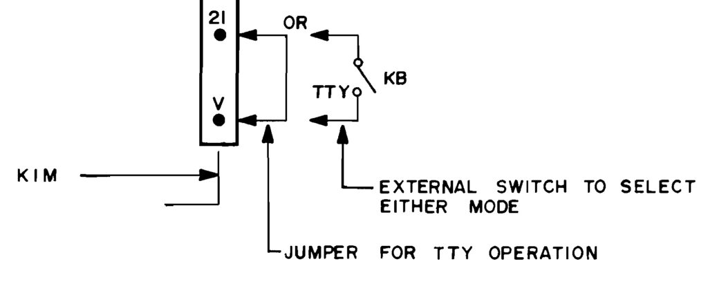
One of the first steps after reset it to determine if the user wants the LED display and hex keyboard or the serial TTY interface.
In the source, you see in several places :
LDA #$01
BIT SAD
BNE TTYKB
   ....
TTYKB keyboard and display
So if bit 0 of Port A (PA0 of SAD) is low, the KIM-1 defaults to the LED display and Keyboard interface.
To enable a keyboard, one must have a switch between PIN 21 and Pin V (PA0 and O3) on the application connector.
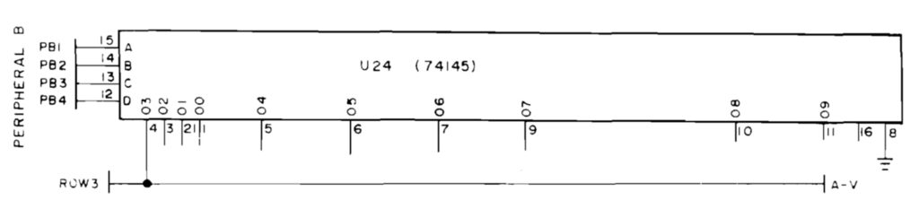
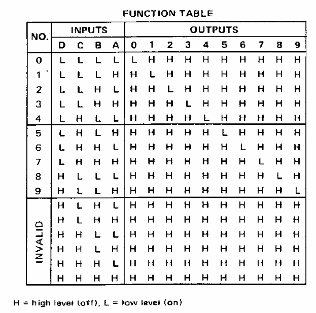
The 74145 decodes PB1 to PB4 to an output. PB1 is connected to Input a, PB2 to B, PB3 to C and PB4 to D.
In fact, this switch is part of the hex keyboard hardware, between PA0 and O3, row 3.
0966   1E88 A2 01       INITS   LDX   #$01       ; SET KB MODE TO ADDR
0967   1E8A 86 FF               STX   MODE
0968   1E8C             ;
0969   1E8C A2 00       INIT1   LDX   #$00
0970   1E8E 8E 41 17            STX   PADD       ; FOR SIGMA USE SAD
0971   1E91 A2 3F               LDX   #$3F
0972   1E93 8E 43 17            STX   PBDD       ; FOR SIGMA USE SBDD
0973   1E96 A2 07               LDX   #$07       ; ENABLE DATA IN
0974   1E98 8E 42 17            STX   SBD        ; OUTPUT
0975   1E9B D8                  CLD
0976   1E9C 78                  SEI
0977   1E9D 60                  RTS
What is happening here?
- In the INIT routine you see Port A Data Direction loaded to 0, which means PA0 to PA7 are inputs.
- Port B Datadirection is loaded with $3F, so PB0 to PB5 are outputs.
- Next $07 is stored at Port B data, so PB1, PB2 are low, and PB3 and PB4 high. This means output O3, Row 3, is low.