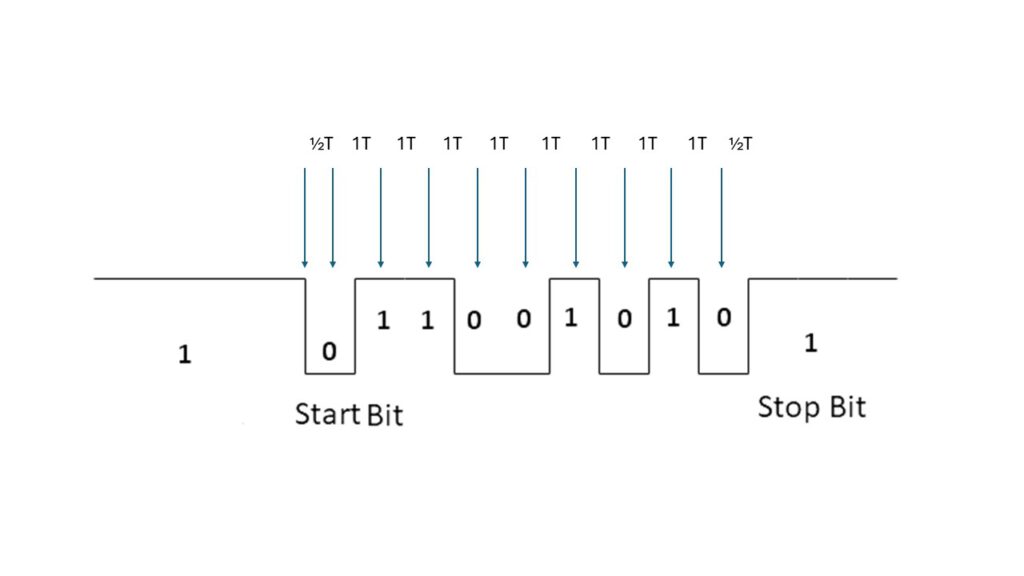
After RESET the baudrate is determined by measuring the length of the start bit of an incoming serial character. This means any character is usable where the first data bit is the opposite of the start bit. The KIM-1 User manual suggest RUBOUT ($7F 1111111) but ENTER ($0D 0000 1101) also works fine. SPACE ($20 0010 0000) for example does not work, any character with an odd value is OK.
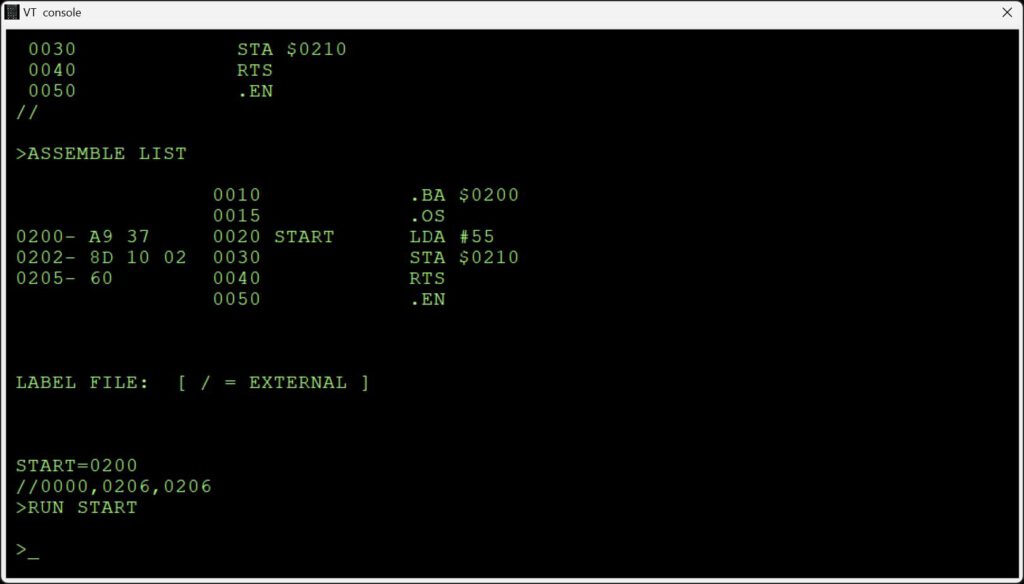
0612   1C2A A9 FF               LDA   #$FF       ; COUNT START BIT
0613   1C2C 8D F3 17            STA   CNTH30     ; ZERO CNTH30
0614   1C2F A9 01               LDA   #$01       ; MASK HI ORDER BITS
0615   1C31 2C 40 17    DET1    BIT   SAD        ; TEST
0616   1C34 D0 19               BNE   START      ; KEYBD SSW TEST
0617   1C36 30 F9               BMI   DET1       ; START BIT TEST
0618   1C38 A9 FC               LDA   #$FC
0619   1C3A 18          DET3    CLC              ; THIS LOOP COUNTS
0620   1C3B 69 01               ADC   #$01       ; THE START BIT TIME
0621   1C3D 90 03               BCC   DET2
0622   1C3F EE F3 17            INC   CNTH30
0623   1C42 AC 40 17    DET2    LDY   SAD        ; CHECK FOR END OF START BIT
0624   1C45 10 F3               BPL   DET3
0625   1C47 8D F2 17            STA   CNTL30
0626   1C4A A2 08               LDX   #$08
0627   1C4C 20 6A 1E            JSR   GET5       ; GET REST OF THE CHAR,
0628   1C4F                                      ; TEST CHAR HERE
What is happening here?
– bit 7 (PB7) is tested until it becomes 0 (BIT SAD and BMI DET1 loop)
– the time is counted and kept in CNTH30 and CNTL30
– bit 7 is tested for becoming 1 (LDY SAD and BPL DET3)
– the rest of the character is read in by jumping into GETCH , the actual character received is not tested.
1006   1ED4             ;
1007   1ED4             ;       DELAY 1 BIT TIME
1008   1ED4             ;       AS DETERMINED BY DETCPS
1009   1ED4             ;
1010   1ED4 AD F3 17    DELAY   LDA   CNTH30     ; THIS LOOP SIMULATES
1011   1ED7 8D F4 17            STA   TIMH       ; DETCPS SECTIONS AND WILL DELAY
1012   1EDA AD F2 17            LDA   CNTL30     ; 1 BIT TIME
1013   1EDD 38          DE2     SEC
1014   1EDE E9 01       DE4     SBC   #$01
1015   1EE0 B0 03               BCS   DE3
1016   1EE2 CE F4 17            DEC   TIMH
1017   1EE5 AC F4 17    DE3     LDY   TIMH
1018   1EE8 10 F3               BPL   DE2
1019   1EEA 60                  RTS
1020   1EEB             ;
1021   1EEB             ;                          DELAY 1/2 BIT TIME
1022   1EEB AD F3 17    DEHALF  LDA   CNTH30     ; DOUBLE RIGHT SHIFT OF DELAY
1023   1EEE 8D F4 17            STA   TIMH       ; CONSTANT FOR A DIVE 2
1024   1EF1 AD F2 17            LDA   CNTL30
1025   1EF4 4A                  LSR   A
1026   1EF5 4E F4 17            LSR   TIMH
1027   1EF8 90 E3               BCC   DE2
1028   1EFA 09 80               ORA   #$80
1029   1EFC B0 E0               BCS   DE4
The actual delay routines use the same logic as DETCPS. IN DEHALF the delay time is divided by 2 and jumped into DELAY.
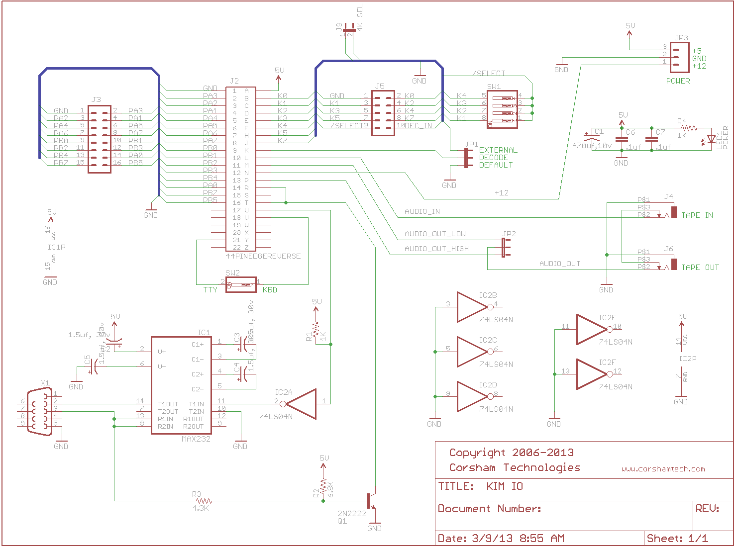
SPEED CONTROL OF KIM-1 TTY PORT
KIM User notes Vol 06
If you are having problems trying to use a high speed terminal with the KIM YTY port the following information might be useful. To start with, the Reset/ Rubout sequence activates a subroutine called DETCPS (1C2AH to IC4EH)
which determines two constants CNTL30 (17F2N1 and CNTH30 (12F3H). These are used to time the serial TTY port via subroutines DELAY (1E4DH to IEEAH) and DEHALF (1EEBH to 1EFDH). DELAY and DEHALF are called by GETCH (
1E5AH to 1E87H) which inputs one character, and OUTCH (1EA0H to 1ED3H1) which outputs one character.
CNTL30 and CNTH30 are the whole key to trimming up the TTY port speed. You can change the baudrate without going through the Reset/Rubout sequence simply by changing one or both of these constants.
The following list gives the values of CNTL30 and CNTH30 for several speeds as determined by my particular KIM-I Reset/Rubout sequence.
BAUD   110  150  300  600  1200 1800 2400 4800 9600
CNTL30 85H  D8H  EBH  74H  38H  24H  1AH  06H  03H
CNTH30 02H  01H  OOH  00H  00H  00H  00H  00H  00H
Now for the interesting part. At lower speeds (110 through 1800 Baud) everything works fine with these values. But, at higher speeds problems arise.
Repeated Reset/Rubout sequences kept producing CNTL30 = 1AH for 2400 Baud. This value did work for most functions like examine and fill memory. however, for tape dump (Q command) intermittent characters were lost.
This problem was eliminated by substituting either 18H or 19H In CNTL30. All functions worked perfectly for either value.
At 4800 Baud I was unable to use the terminal at all. It acted more like it wanted to work at CNTL30 = 07H rather than at 06H, but no value between 05H and OAH would make it work.
At 9600 Baud the slow functions like examine and fill would work, but tape dump (Q) resulted in severe loss of characters.
The problem at these speeds is that the quantization level between allowed speeds (i.e. integer values of CNTL30) is so large that unless you are lucky you will not hit close enough to your terminal speed.
Since CNTL30 as used in a software timing loop to count instruction sequences (thus machine cycles) the high Baud can be fine tuned with the system clock.
You should be able to use the technique described by R. H. Burhans (page 10, issue #5. May 77, KIM-1/6502 Users Notes) to perform this fine tuning.
For casual use, 2400 Baud (or maybe even 110 Baud) is satisfactory with no hardware modifications.
However, if you have a dedicated high speed terminal you may find it worthwhile to fine tune either the KIM-1 clock or the terminal clock.
This will allow you to utilise the KIM-1 software (like GETCH and OUTCH) at high speeds. After you become accustomed to it. 9600 Baud is nice. 2400 ok, 1200 a bit of a drag. and anything less unbearable.
Finally, since CNTL30 • 03H (greater than zero) for 9600 Baud you should be able to fine tune for 19,200 Baud. and maybe (but probably not) for 38,400 Baud. Dwight D. Egbert
Jim mcClahanan notes
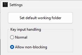
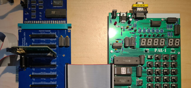
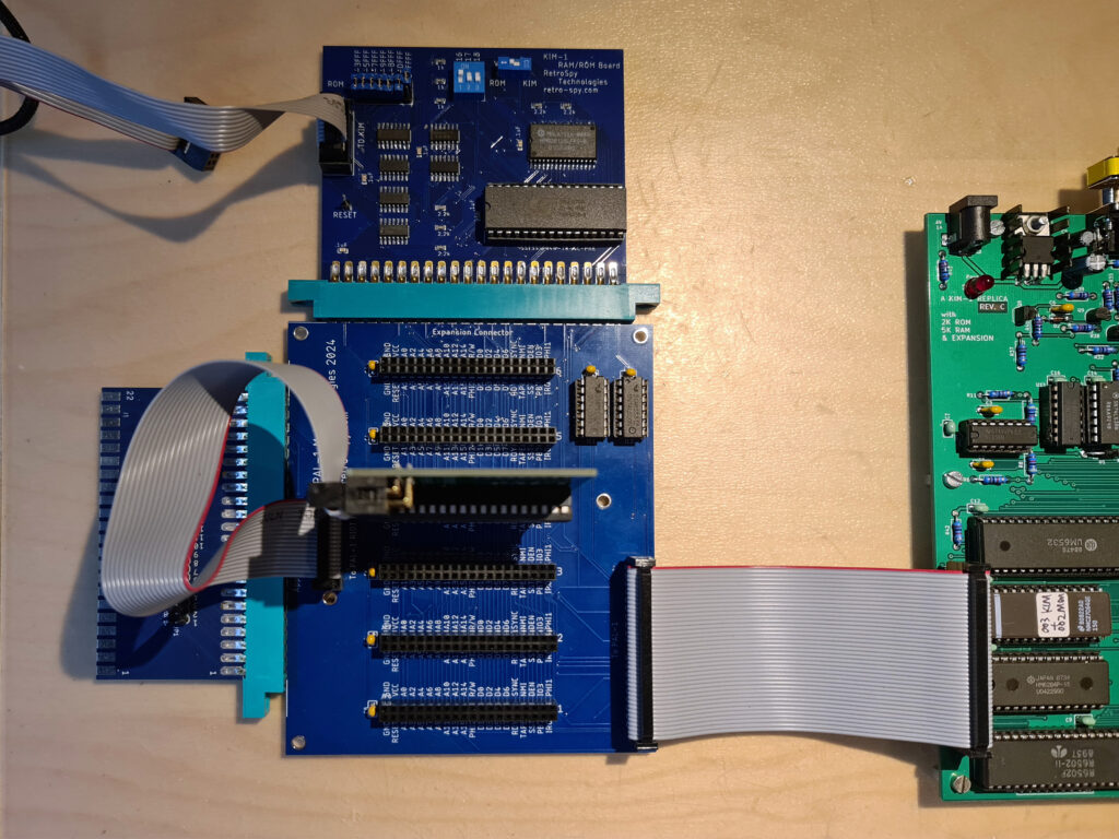
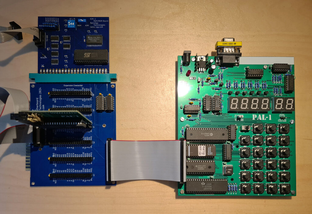
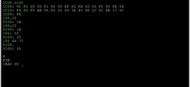
The PAL-1 (just like the KIM-1) uses a ‘soft UART’ or ‘bit banger’ for its serial I/O. I’m not a fan of this approach, but at the same time it demonstrates what could be accomplished with a minimial amount of hardware. The PAL-1 automatically figures out the appropriate delay between bits of the serial character when you press enter after a reboot. I have found that decreasing the value actually significantly improves the odds of an error-free load of larger punchtape format files. Below is a table for values found and suggest for $17F2.
Baud    Found   New
300     $EA     $E8
1200    $37     $35
2400    $1A     $18
4800    $0B     $0A
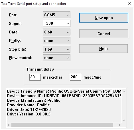
I haven’t tried to optimize the delay values. Right now I’m using 5 ms between characters and 500 ms between lines when doing 8K transfers and with the modified values I usually am successful. With the default values, it seemed like even with longer delays things would slip out of synchronization at some point more often than not on large transfers.