 A Colossal Cave Adventure on a KIM-1? Yes, within the limits of the seven segments LED, and the 1K RAM?
The late-70s labor of love by Bob Leedom to create a mini (nano?) version of Colossal Cave Adventure is not lost.
Like Micro-Chess, amazing what can be done with the unexpanded KIM-1!
The original document with (assembled by hand!) source from Bob Leedom has been OCR’ed and converted into loadable tape and papertape files by Dominic Bumbaca and also by Mark Bush.
Dominic also made a recording on Youtube of him playing the game.
Here I present what I have now on this game:
(with thanks to Bob Leedom, Dave Wiliams, Dominic Bumbaca, Mark Bush and Nils)
– PDF with instructions, source code and map (from archive.org)
– Game instructions in PDF
– Papertape files by Dominic Bumbaca
– tape recording by Dominic Bumbaca
– HEX dumps of program Dominic Bumbaca
– Youtube recording by Dominic Bumbaca
– Local copy the Mark Bush Github repository
– Papertape files by Mark Bush
– Intel hex files by Mark Bush
– Assembler sources files by Mark Bush
– Corrected hexpawn100 papertape thanks to Nils
Notes by Mark Bush (see his repository here)
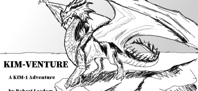
KIM-Venture
KIM-Venture is an adventure game based on Colossal Cave written for the KIM-1. The program and its documentation are Copyright © Robert Leedom and we make no claims to any of this material. I (Mark Bush) have gathered everything together here for posterity.
Installing and Running
Included here are both paper tape and HEX format files. The HEX files can be used on a KIM-1 clone from [Corsham Tech](https://www.corshamtech.com), especially if you have their SD card system.
Load the `Venture-ZeroPage`, `Venture-Game`, and `Venture-Extra` files in any order.
Start the game by going to address `$0100` and pressing `GO`.
When you are finished, load `Venture-Scoring` and run from `$0100` to see how you did.
Note that the scoring program overwrites some page zero locations. If you want to be able to go back to your game after seeing your score, then you will need to save page zero first, then run the scoring program, then load your saved file and also `Venture-Game` again and restart at `$0100`.
The original tape IDs of these files are:
ID | File
—|—–
A1 | Venture-ZeroPage
A2 | Venture-Game
A3 | Venture-Extra
06 | Venture-Scoring
Note for KIM-1 clone users
If you are using the KIM-1 clone, then you will not be able to load the `Venture-Game` or `Venture-Scoring` as HEX files from the SD card system completely because the extended monitor uses the stack. Load them from the paper tape files instead.
Saving a Game
You can save the state of your game by saving a copy of zero page (from `$00` to `$EE`) and making a note of the contents of location `$03BD`.
Return to the game by loading your saved file instead of the original zero page data when you load the program and setting the contents of `$03BD` to the value you noted.
For the full version mentioned below (in an expanded KIM-1), record and restore the contents of `$04BD` instead of `$03BD`.
Instructions
Included here are:
* The Instructions] for playing the game.
* The Game Manual containing information about how to load and run the game
Source Code
The `source` directory contains the original source code for the game with all original comments and formatting preserved. There is one change from the original, though. In `Game.asm` in the Main Move Loop, the original code used absolute addressing for the `INC NMBUTS` statement. [My assembler](https://github.com/markbush/6502-assembler) uses zero page addressing when possible which would make this a 2-byte instruction instead of 3-byte, so I have added a `NOP` to preserve addresses in the output.
The following files contain the source code:
File         | Content
-----        | ---------
ZeroPage.asm | data to be loaded into zero page
Light.asm    | The LIGHT subroutine which compiles into the start of zero page
Game.asm     | The actual game which loads into pages 1, 2, and 3
Extra.asm    | Some support subroutines which load into the 6530 RAM
Scoring.asm  | The scoring program
These source files (except `ZeroPage.asm`) are location agnostic.
This allows them to be recompiled into alternate addresses.
The above code can be compiled using the following files:
File                 | Content
-----                |---------
Venture-ZeroPage.asm | Combines LIGHT with the zero page data
Venture-Game.asm     | Creates the actual game
Venture-Extra.asm    | Creates the file loaded into 6530 RAM
Venture-Scoring.asm  | Creates the scoring program
Venture-Full.asm     | Creates a combined program for a KIM
                       with extended memory (or the KIM-1 clone)
These files are necessary as the individual source files refer to locations and subroutines located in the other parts. They can only be assembled together. Each of the above files contains a directive causing only the relevant part to be output, enabling the separate program files to be created.
For the `Venture-Full` version, the game starts at `$0200` instead of `$0100` and avoids using any locations in page 1 (the 6502 stack). You can stop the program to view your score at any time. Press `ST` to stop the program and change to address `$0600` and `GO`. Press `ST` again and rejoin the game from `$0200`.
The `Venture-Full` file does not include the zero page data so that must be loaded separately and will update the location of the message table in POINTR when run. This is partly to avoid trying to load data through stack locations (which could mess up the loading process) and also to make it easier to keep copies of the zero page data in order to save the state of a game.
Saved copies of zero page from the original multi-part program can correctly be used by this full version (because it updates the location of the messages), but if you wish to use a copy of zero page from the full program with the original, then you will need to change the contents of location `$4B` to be `$03` after loading.
**NOTE**: The `Venture-Full` version is a work in progress – try it at your own risk!!