
 So I have a collection of those USB to serial adapters, some with cables and DB-9 connectors, some with cable and Dupont connectors, and some USB TTL type connectors on a PCB with male or female Dupont pin connectors for USB-A, mini or micro USB. Most not documented or unsure if the voltage levels are 3.3V or 5V ..
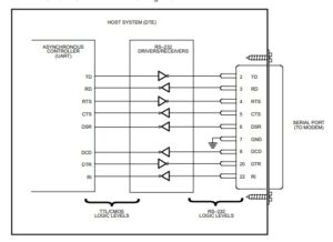
First some background. These are all descendants of the EIA RS232 standard in some way. Terminology, asynchronous serial format, voltage levels, start bits, stop bits, 7 or 8 data bits, hardware and software handshake, and the way it is abused in many of these devices. And so common nowadays in Arduino and ESP8268, ESP32 and even Raspberry Pi world.

If you are new to the serial world and want to use these devices and understand how, study the next chapter. You will learn and know what I am talking about: DCE, DTE, DSR, DTR, TxD, RxD, CTS, RTS, DTR, RI, CarrierDetect, UAR/T’s, TTL voltage levels being reverse to RS232 voltage levels, a ‘0’ being negative RS232 voltage up to 15V, a ‘1’ being as low as -15V.
RS232 asynchronous information
 This picture shows where RS232 came into being about 50 years ago,
Read these PDF’s:
RS232 Protocol – Basics
EIA RS232-C Standard Protocol
EIA RS232-E Standard Protocol
Fundamentals of RS–232 Serial Communications
RS232 Physical Layer Interface Standards
RS232 (TIA/EIA-232-F)
RS-232: Serial Ports
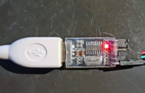
USB Serial TTL devices
These little devices came into use to communicate with small computers like SBC’s, Arduino and ESP’s and PC’s. Throw out the overhead of the + and -15v, limit or leave out the handshake signals, (mis)use the DTR signal to reset the Arduino, use it to download firmware or collect data from sensors on the small computers and process it on bigger machines. And act as the power supply the little computer.
Based on special UAR/T IC’s, very small footprint, and dirt cheap.
Testing USB Serial TTL adapters
What you need:
– A PC, Raspberry Pi or another Linux or Windows PC. Any PC platform supporting USB ports will do.
– The program SerialTester, see below
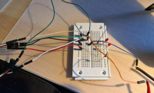
– A small breadboard
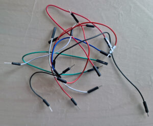
– A collection of Dupont cables with male and female connectors
– A multimeter, a most simple one will do
 |
 |
 |
 |
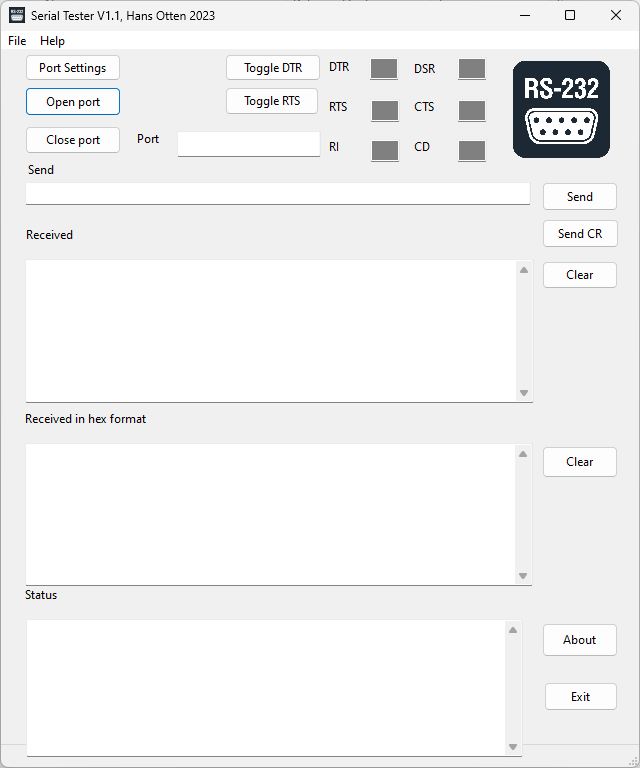
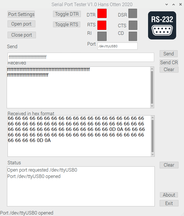
SerialTester
Testing USB serial adapters is not that difficult, you need a terminal emulator, which are available in lots of formats and capabilities. Putty, Minicom etc all allow to choose a serial port, set baudrate and other parameters like hardware handshake, software handshake, number of data and stop bits. With a loopback test (which means connecting serial out TxD to serial in (RxD) you can test the serial connection by typing characters and seeing the characters appear on screen.
What I miss in these programs is a way to inspect the modem control lines. So I wrote a little program for that.
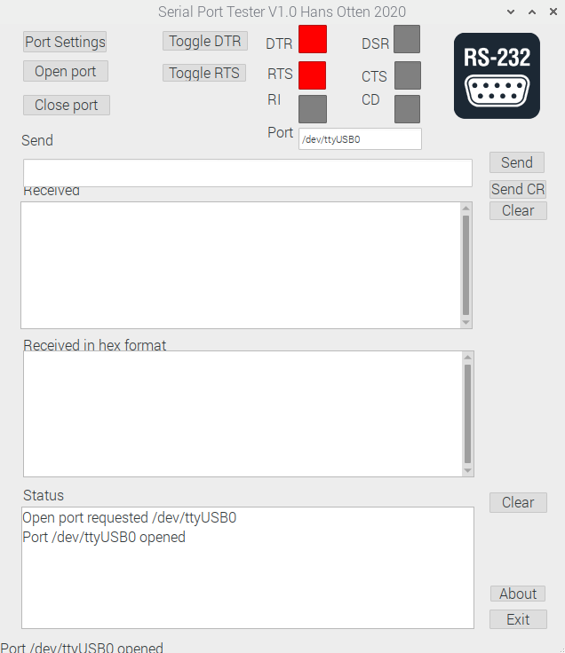
SerialTester allows to do the loopback test and shows the state of the modem control lines.
You can change the DTR and RTS lines since these are set of cleared by the USB serial port. The other lines are read from the USB serial adapter.
Get the program here:
– Setp for Windows, Ubuntu, Raspberry Pi
– source (Lazarus + Freepascal)
Use the program as follows to completely test and document (write down test results on the next steps!) the adapter.
1. It is a GUI/Windows program, so start as usual on your operating system. Raspberry runs this program fine, but Linux is not so forgiving in plug and play of USB devices, so expect some hangs and reboots. CH340 chipsets can have a temper, and SerialTester sometimes fails, where Minicom succeeds.
2. Insert the USB adapter, do not connect anything yet to the adapter
For the USB-A types it is handy to have an USB-A male -female cable to bring the adapter to the table
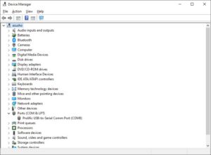
– Check if the USB adapter is recognized by the operating system
For Windows start Device Manager and look for COM Ports, like COM8 in the example below
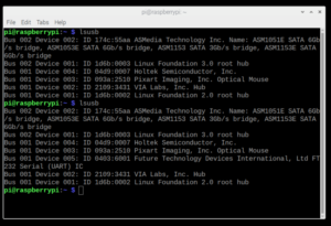
On Linux start a terminal and type “lsusb”, insert the USB serial adapter and look for added USB device serial adapter, in the screenshot an FTDI adapter.
The command “ls -l /dev/ttyUSB*” will show devices like “ttyUSB0”.
 |
 |
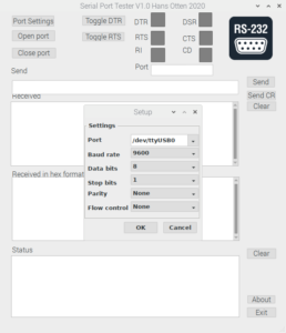
3. Click Port settings and click in the field Port drop down button. A list of serial adapters will be shown, pick one. Note that on a Raspberry the serial port ttyAMA0 on the GPIO connector will be shown also. Here we want the ttyUSBxx device.
Select 300 baud as baud rate, this will help seeing the transmit with the multimeter., leave the rest default.
Press OK
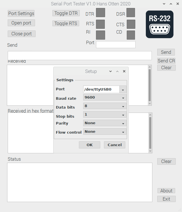
4. Open the Port by clicking the button Open Port. Look at the status displayed, it should tell the port is opened. If not opened, you might have a driver problem, see the sections below on CH34x, FTDI and Prolific 2303HX devices.
You will also see the DTR and RTS fields light up red, as opening also sets the DTR and RTS pin high.
5. Switch on the multimeter and read the prints on the USB or the color of the wires.
– First find Gnd. Indicated with the label GND or a black wire.
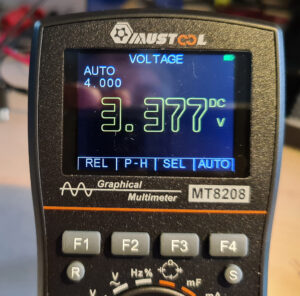
– Now find Vcc, indicated with VCC or the red wire. Measure the voltage, should be 5V, 3.3V. Some adapters have a jumper to select the voltage. Some adapters also change the voltage on the other lines, some do not. Measure!
6. Find the TxD pin. Connect the multimeter to the TxD pin. It should be +3.3V or 5V. Also check if changing VCC to +3.3V or 5V makes any difference, some adapters do, some do not change the voltages on the pins.
7. Enter a long string in the Send field, and press Send (or Send CR for a line ending). Observe the readout on the multimeter, it should be lower than the value in rest. Nothing will be shown in the received fields.
 |
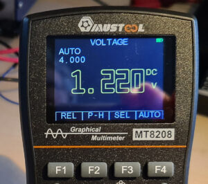 |
If not, then this is not the transmitting pin. Check RxD if that is the transmitting pin, for all my adapters it was TxD, but who knows what manufacturers do ..
8. Inspect the adapter for a DTR line if any. Connect the multimeter to the corresponding pin and measure the voltage. Press the DTR button in SerialTester and check if the voltage changes on the pin.
 9. Repeat for the RTS line.
10. Locate the RxD line. Connect this line to the TxD pin and send a string again. Now you should see the Receive and Receive hex fields filled with the send string.
11. Now if any pins are not tested yet, they have to be the other modem control lines. The labels on the adapter will tell or experiment and measure. Connecting to ground or VCC with a 2k2 resistor (to be safe) will show on the display of the SerialTester program the corresponding level.
Chipsets: FTDI, Prolific, Silicon Labs, CH340
The USB Serial adapters contain a UAR/T IC, made by a small group of manufacturers.
1. FTDI. Comes with the highest recommendations. Many types. Well supported in Linux and Windows.
Due to fake IC’s made in China the current drivers check and try to make a fake inoperable.
If you encounter in Windows a non-working FTDI adapter, you cna only use it in Linux, after ‘repairing it. See here how to do that.
2. Prolific. Supported in Linux and Windows.
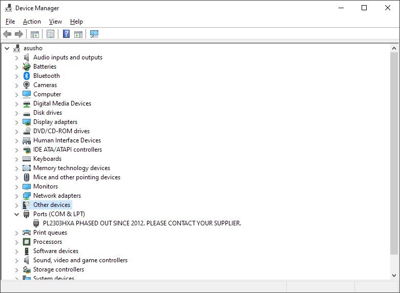 Also due to fakes, older (not fake!) IC’s made by Prolific are not supported by the current Prolific driver in Windows. Device manager shows PL2303HXA PHASED OUT SINCE 2012. PLEASE CONTACT YOUR SUPPLIER.
Easy to solve with an older version of the driver, see this page how to do it!
3. CH34x. I sometimes encounter problems under Linux with this chipset. Windows runs fine.
Reports
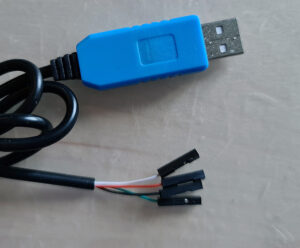 |
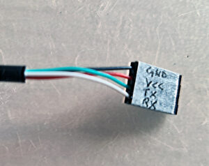
‘Blue’ closed connector with cable Prolific PL2303 Male Dupont connectors Black Gnd Red +5V Green Tx (sending data) 3.3V Yellow Rx (receiving data) |
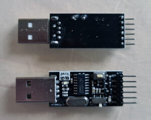 |
Betemcu CH340 Status LED red, send LED blue Edge pin connector maleGND Gnd VC +3.V or 5 V slide switch TX 5V Sending Rx 5V receiving DTR 5V CTS connect ground for ‘on’ Button switch of Vcc |
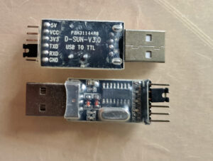 |
D-Sun-V3.0 CH340 Status LED red Send blue led Received blue led Edge pin connector male GND Gnd RxD receiving TxD sending at 3.3V or 5V 3V3 3.3V Vcc jumper to +3.3V or 5V (no jumper 3.3 V) 5V 5V |
 |
Tienu ZX2H1911A1 PL2303HXA Status LED red Sending green LED Receiving Yellow LED Edge pin male 5V 5V 3.3V 3.3V TxD sending 3.5V RxD receiving 3.5V Gnd Gnd |
 |
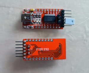
FTDI DCORSO FTDI 232 Red status LED send receive green LEDs Edge pin male Jumper +5V Vcc +3.V Jumper 5V – Vcc – 3.3V All modem signals to edges RI CTS RTS 110 baud not supported DTR 5V or 3.3V following jumper TX sending 5V or 3.3V following jumper RX receiving 5V or 3.3V following jumper VCC 5V or 3.3V following jumper CTS 5V or 3.3V following jumper Gnd Gnd |
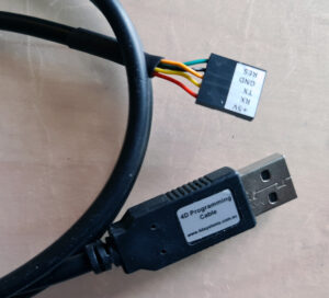 |
4D Programming Cable CP2102 Dupont female RES ? Gnd Gnd Tx Sending 3.4V Rx Receiving 3.4V +5V 5V |
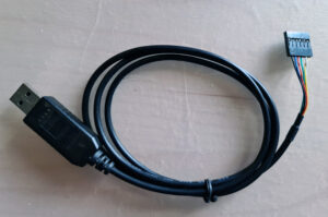 |
FTDI cable no ident, lights in cable red (receive) green (send) Dupont female Black Gnd Blue CTS 3.4V Red +5V Green Sending 3.4V White Receive 3.4V Yellow RTS 3.4V |
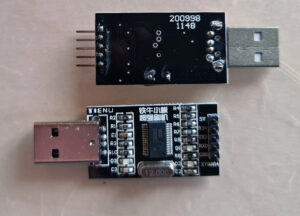 |
Tienu FTDI232H USB-A FTDI edge pin red status LED green send, yellow receive GND Gnd RXD Receive at 3.5V TXD Sending at 3.5V 3.3V 3.4V 5V 5V |
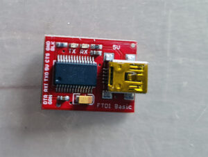 |
FDTI basic Sparkfun female dupont bottom Mini USB GND Gnd CTS 5V 5V 5V TxD sending 5V RXI receive 5V DTR 5V |
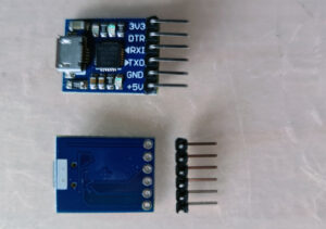 |
Square CP210X Red status LED Red LED send Red LED receive Micro USB Male Dupont Edge 3V3 3.3V DTR 3.4V RXD sending 3.4 V TXD receive 3.4V GND Gnd +5V 5V |
 |
FTDI232 Mini USB Jumper 5V – Vcc – 3.3V All modem signals to edges. Voltages follow Jumper setting. |
 |
MBC2 cable Prolific 2303 black GND red 5V Vcc Green TX sending at 3.4V White Rx |
 |
UC-2102 Cable CP210X Male edge pin connector DTR 3.4V RxD TxD sending 3.4 V +5V +5V GND GND |