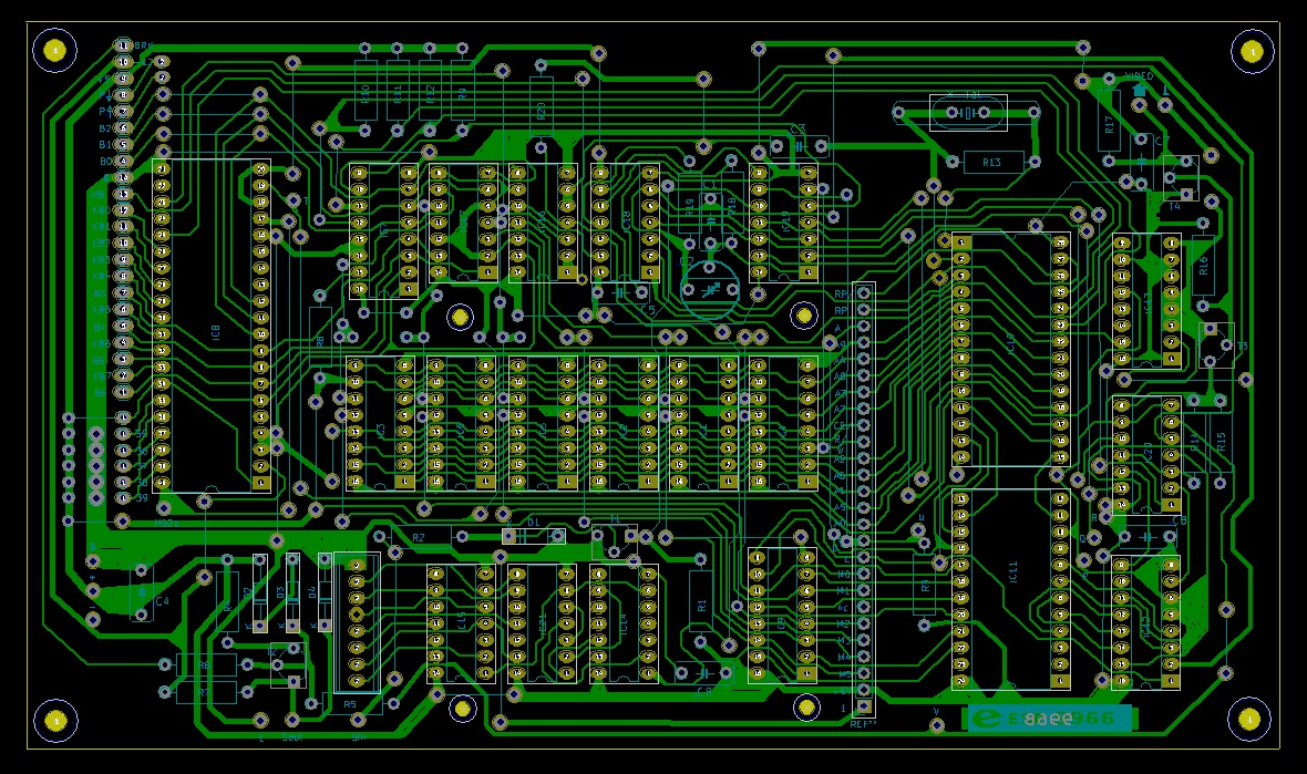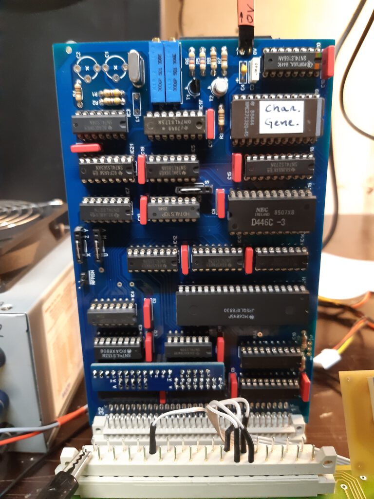
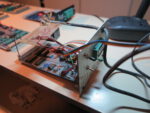
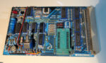
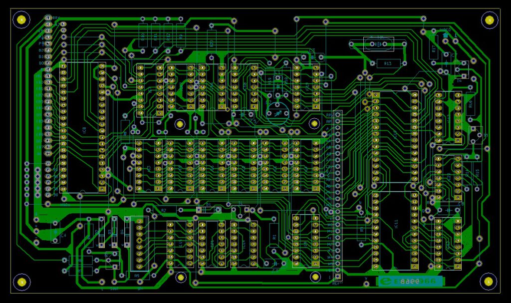
This is a replica PCB made with KiCAD.
This board is not a 100% accurate replica, because the added directly on the PCB a few updates published later by Elektor :
- a fix for memory decoding needed for the expansion board
- the main decoupling capacitor C2 was on wrong side of S25 (activate display) which could reset the computer
- a simple reset circuit with a resistor and a capacitor
- Also replaced the 2708 EPROM by a 2716, which avoid the need of a hard to find EPROM & EPROM programmer, and has the big benefit of reducing the required power supplies from 3 (+5,-5,+12) to only +5V.


More details, also yet untested Interface card and other cards at his github page.
See also:
KIM-1 Simulator documentation
KIM-1 Simulator
Hans Otten, Eduardo Casino, 2019- 2026, Version 2.0.0 beta
Contents
Introduction
Installatio...
DIY KIM-1 Keypad
A spare KIM-1 keypad is even rarer than a KIM-1 itself. With this guide you can build a reasonable replica of the ke...
Proton PIM-1
Gerben Voort acquired a microprocessor development system PIM-1 developed by Proton, of PC-1 fame.
Here his photos of...
PROTON Electronics: PC-1, CB80, PIM-1
PROTON Electronics, a small company from Naarden the Netherlands, led by James Post, and A.J. Kool as technical manager,...
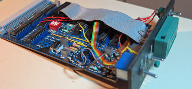
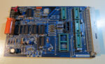
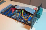
A programmer for 2716 and 2732 EPROMS with the Elektor bus, PCB EPS82010(A).
Many users build this programmer, often with extending the EPROM ZIF socket and switches to the frontpanel of the card, so they are accessible.
The photos show PCB EPS82010A, that revision had the Junior adaptations as outlined in the 1983 article.
See also:
KIM-1 Simulator documentation
KIM-1 Simulator
Hans Otten, Eduardo Casino, 2019- 2026, Version 2.0.0 beta
Contents
Introduction
Installatio...
DIY KIM-1 Keypad
A spare KIM-1 keypad is even rarer than a KIM-1 itself. With this guide you can build a reasonable replica of the ke...
Proton PIM-1
Gerben Voort acquired a microprocessor development system PIM-1 developed by Proton, of PC-1 fame.
Here his photos of...
PROTON Electronics: PC-1, CB80, PIM-1
PROTON Electronics, a small company from Naarden the Netherlands, led by James Post, and A.J. Kool as technical manager,...
After several years so much new and correct information has been coming in!
While I was studying the Comal interpreter, I want to port it to the KIM-1, I realised the Elektor pages required some updating and reorganising.
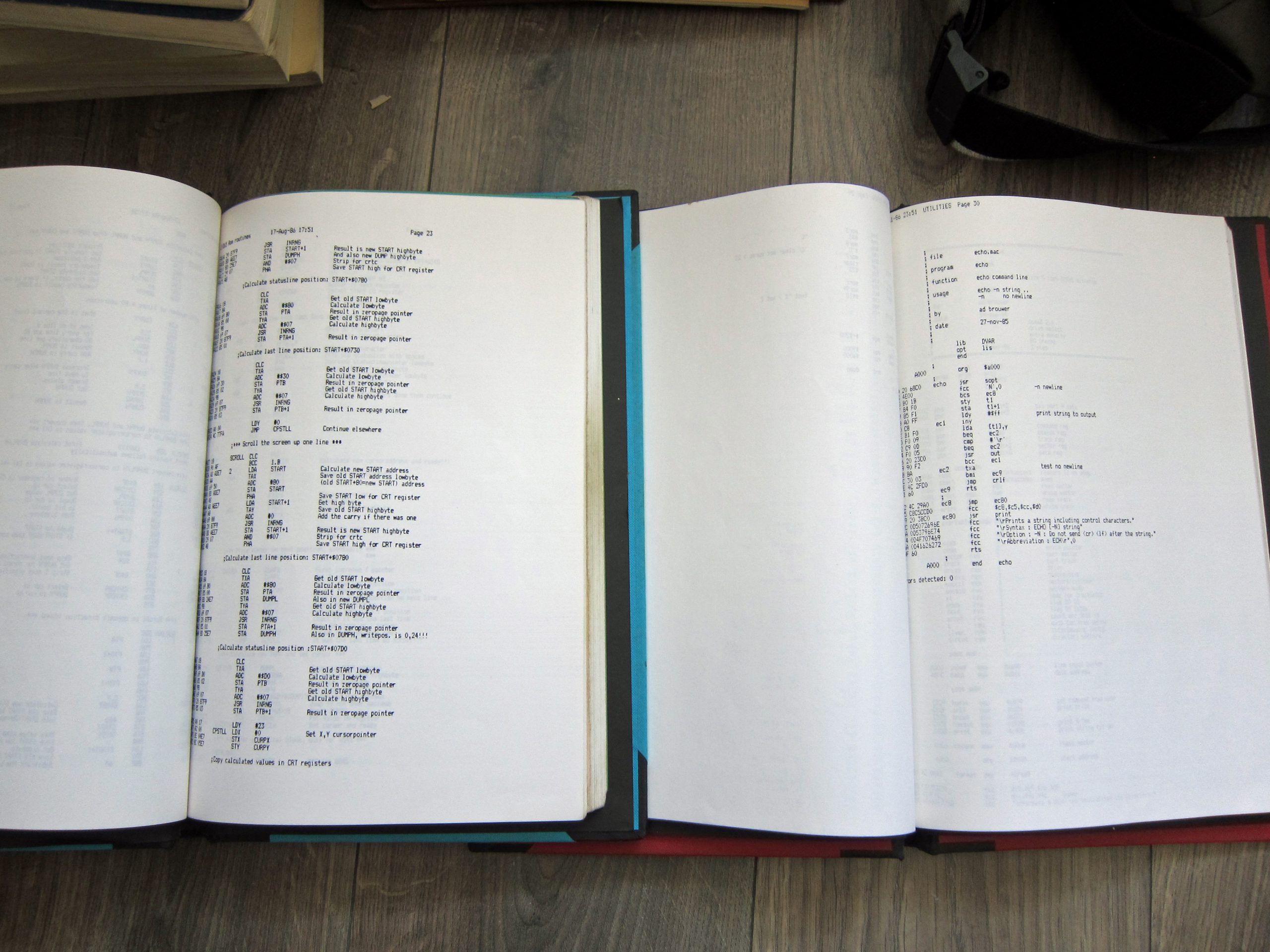
I could not find easy what I needed: circuits and source listings. So I extracted the circuits from the articles and checked the various listings with the ROMs I had in my archive.
Also the sources that appeared the last years were checked, adapted and the binaries compared with the hex dumps. Some surprises, many faults and not with the correct names.
The ESS numbers are now attached to the ROMs.
Now you can have all the essential Elektor Junior information from base to full system with checked ROMs, with sources, step by step.
The complete archive of articles and books is also updated, especially the English articles are as complete as possible.
Have a look at the Elektor Junior pages!
With thanks to the many persons and fora that helped me to collect the information.
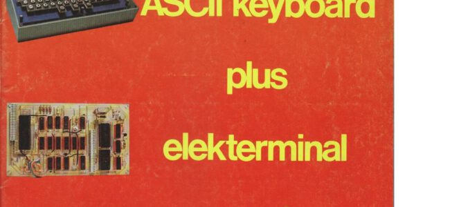
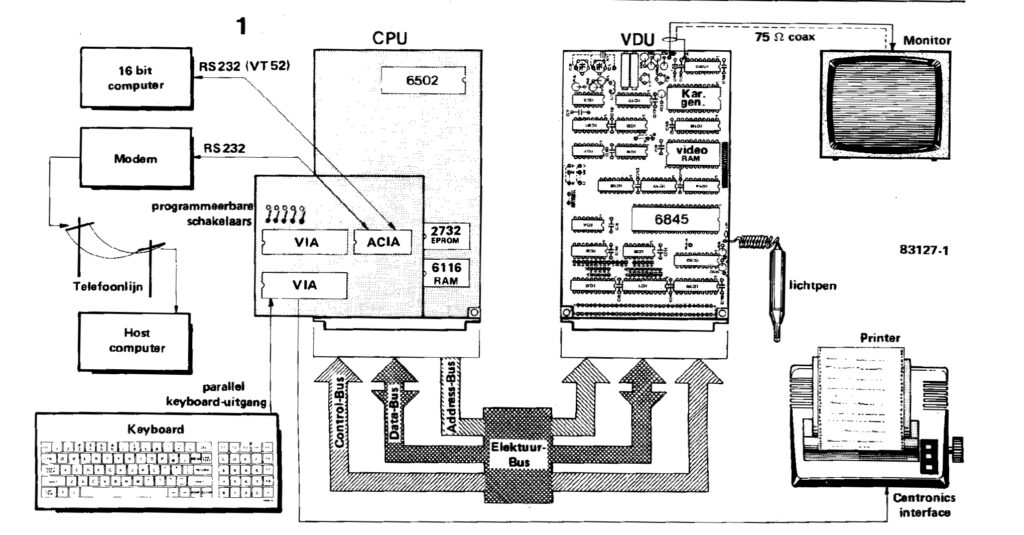
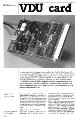
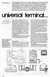
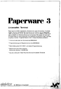
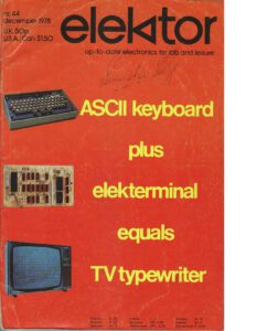
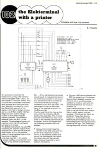
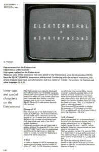
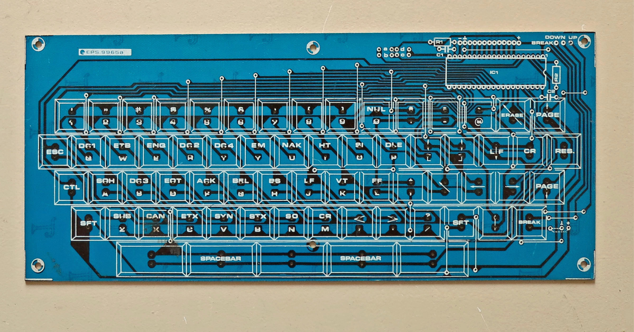
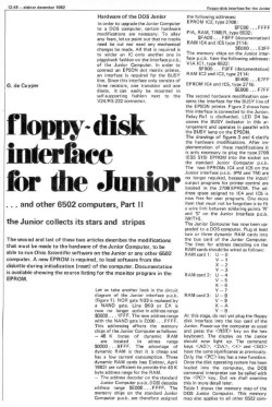
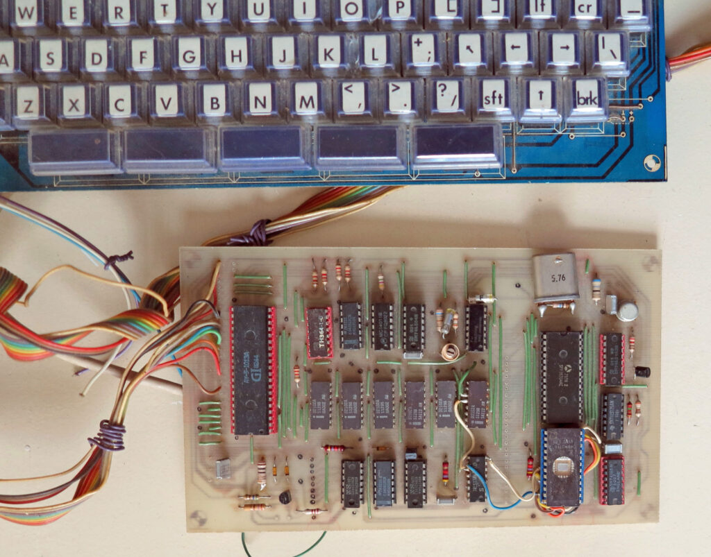
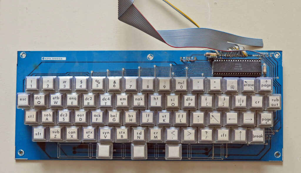
Elektor published in 1978 the Elekterminal design: a video display unit and an ASCII keyboard for computer systems with serial interface.
Over the years the design evolved and many articles were published. Among other systems, it was also integrated with the Junior computer.
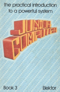
The Juinor book 3 contains a detailed description how to combine Elekterminal and Junior via the bit banged serial TTY interface.
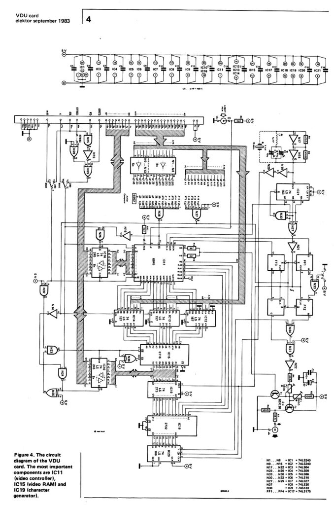
The video display was later replaced with a videocard, the serial ASCI keyboard stayed as option.
Articles and books in English about the Elekterminal

See also:
KIM-1 Simulator documentation
KIM-1 Simulator
Hans Otten, Eduardo Casino, 2019- 2026, Version 2.0.0 beta
Contents
Introduction
Installatio...
DIY KIM-1 Keypad
A spare KIM-1 keypad is even rarer than a KIM-1 itself. With this guide you can build a reasonable replica of the ke...
Proton PIM-1
Gerben Voort acquired a microprocessor development system PIM-1 developed by Proton, of PC-1 fame.
Here his photos of...
PROTON Electronics: PC-1, CB80, PIM-1
PROTON Electronics, a small company from Naarden the Netherlands, led by James Post, and A.J. Kool as technical manager,...
Junior KB9 Basic
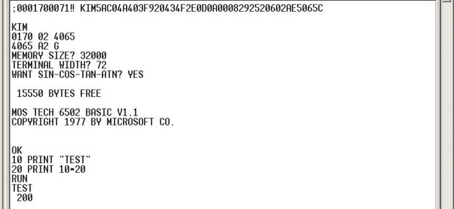
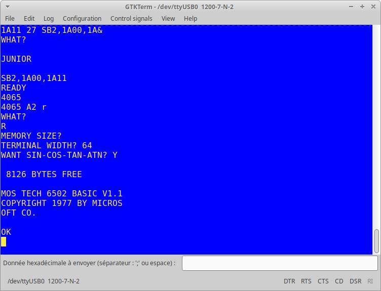
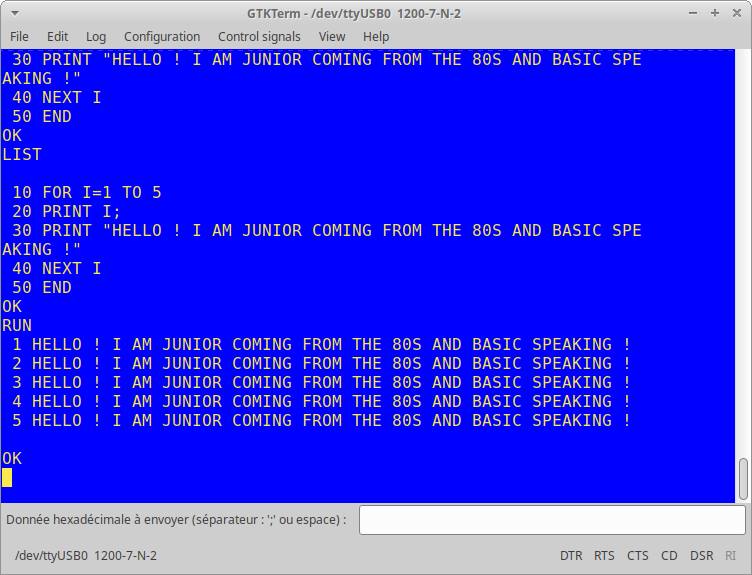
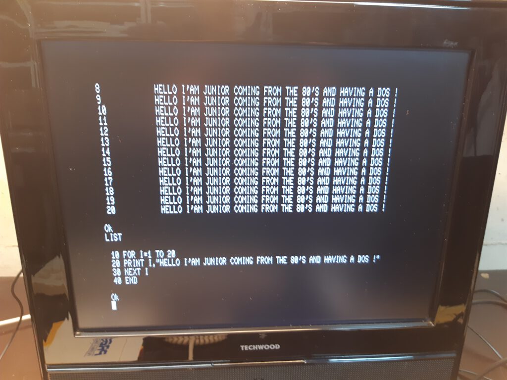
Philippe Roehr started with the KB9 binary from the KIM-1 pages.
Philippe then applied the process outlined in the Elektor articles to adjust Basic to the Junior character I/O routines and also improved the speed by adjusting the now unnecessary code that took care of the ROR bug in early 6502’s.
Philippe transferred the binary to the Junior with Ed’s utility KIMTape, producing a KIM-1 audio wave file. The Junior accepts this format, a bit slow but only needed once. After seeing all was well, Philippe wrote the now optimized Junior KB9 Basic to audio wave file, and made a hex dump on the terminal. I picked up the dump, a captured text file form a a terminal emulator, and wrote a conversion program to produce a binary.
All the files here: archive with audio wave file, dump on terminal, binary and conversion software.
See also:
KIM-1 Simulator documentation
KIM-1 Simulator
Hans Otten, Eduardo Casino, 2019- 2026, Version 2.0.0 beta
Contents
Introduction
Installatio...
DIY KIM-1 Keypad
A spare KIM-1 keypad is even rarer than a KIM-1 itself. With this guide you can build a reasonable replica of the ke...
Proton PIM-1
Gerben Voort acquired a microprocessor development system PIM-1 developed by Proton, of PC-1 fame.
Here his photos of...
PROTON Electronics: PC-1, CB80, PIM-1
PROTON Electronics, a small company from Naarden the Netherlands, led by James Post, and A.J. Kool as technical manager,...
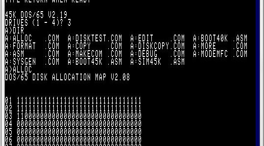
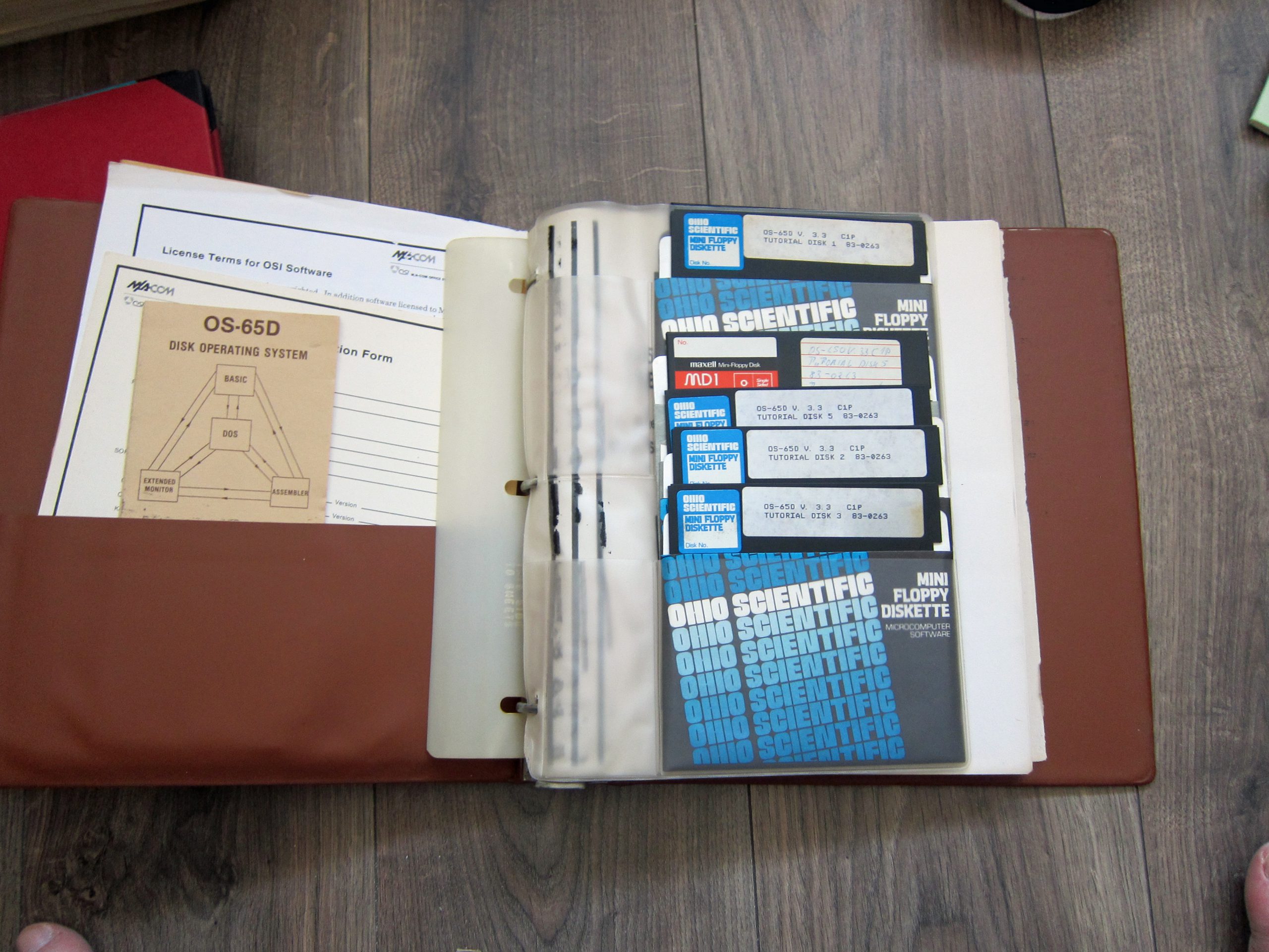
OS65DV3.3
Based upon information supplied by Philippe Roehr, see also the DIY Build a Junior page
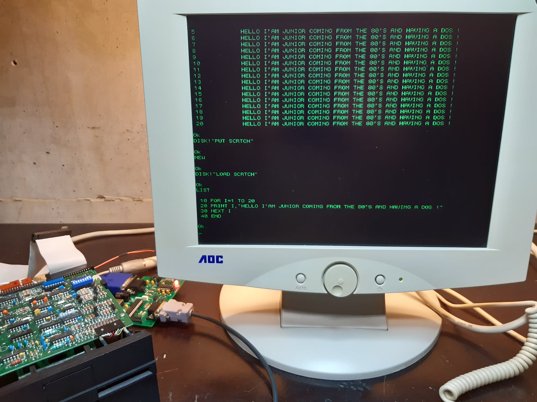
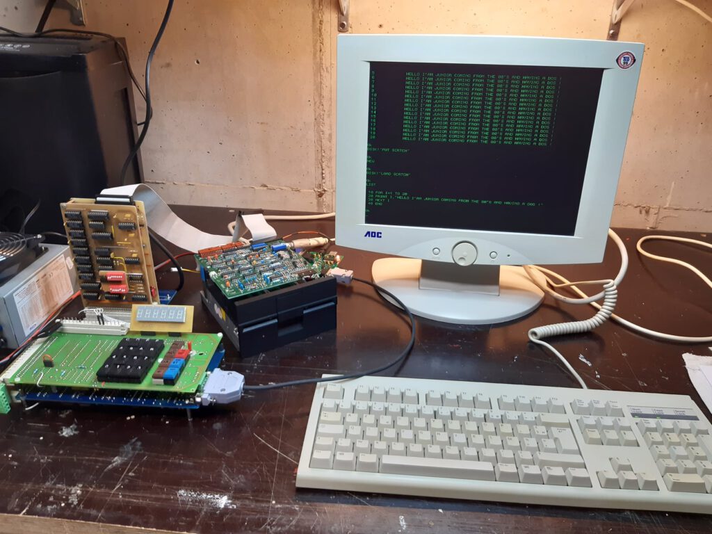
After building the Junior, having PM and TM monitor working well, KB9 Basic operational, the next step Philippe took was getting the operating OS65Dv3.3 operational.
He took the steps described by Elektor in the articles with some modern additions.
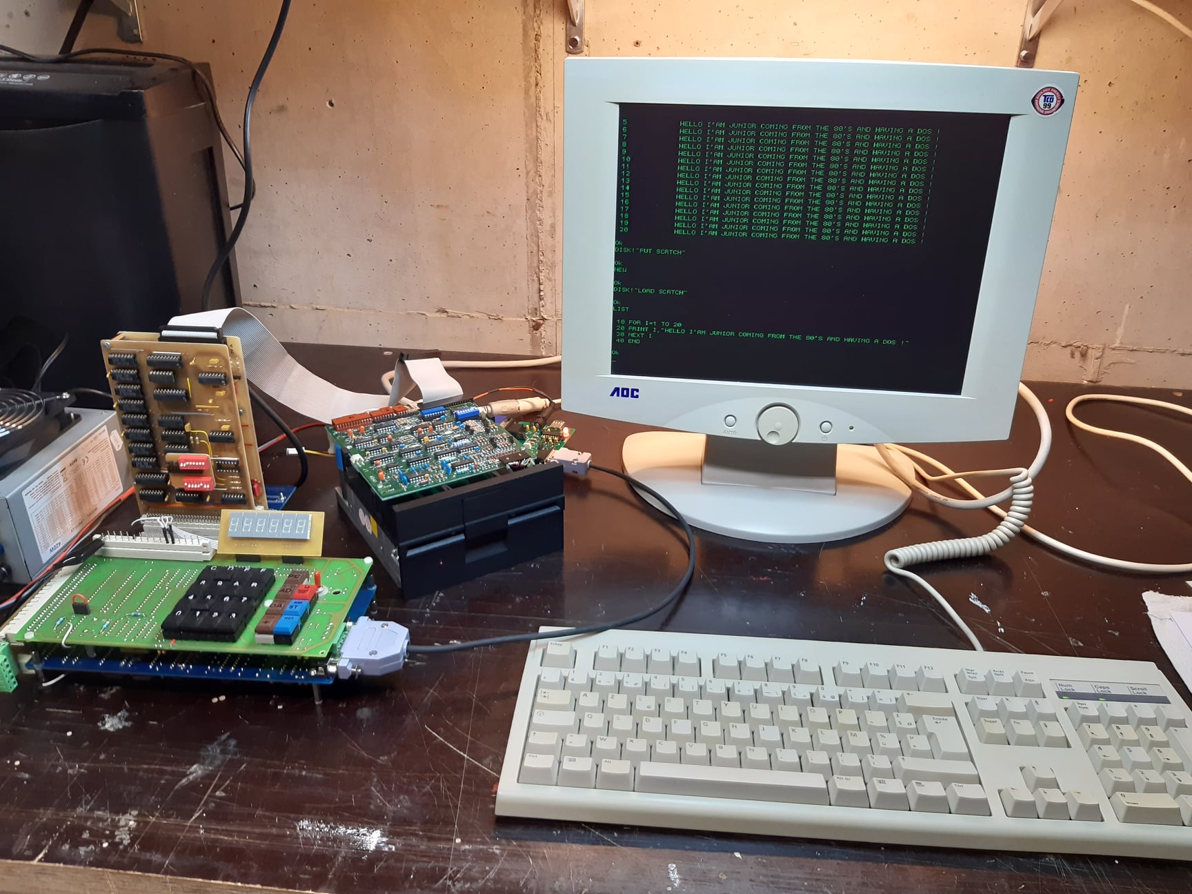
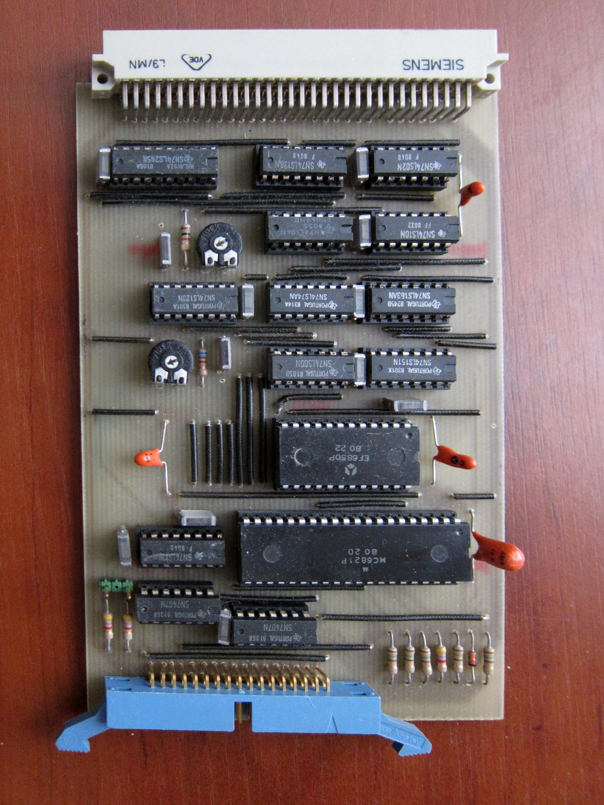
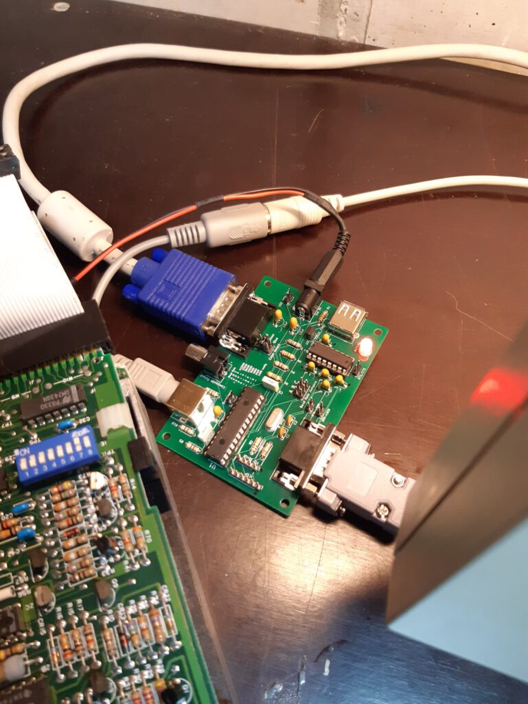
A Junior able to run OS65DV3.3 needs an expansion card, a RAM card (his is 64K) and the Elektor floppy controller, which is identical to the OSI one (6850 + 6820 ICs)
Instead of a real floppy drive Philip used the hardware Gotek floppy emulator with the Flashfloppy firmware. And used the manuals images of http://osiweb.org, and the OSIHFE utility described in the OSI Web forum posts.
Elektor made a bootstrap eprom (see the floppy disk page) able to
* load OS65D (V3.1 or 3.3 as far as I know) from floppy
* give basic I/O capability (RS232 and floppy)
* manage hex display and keyboard
* modify OS65 for the hex display after the very first load to fully adapt them to the system ( about 10 bytes to modify)
Here the OS65DV3.3 disk image in native and Flashfloppy format ready to use.
During the second part of december 2020 Philippe added a real floppy controller and added the Ascii Video Terminal (new version of hackaday). With improved moter control of the floppy drive!

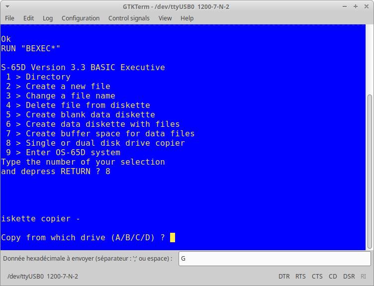
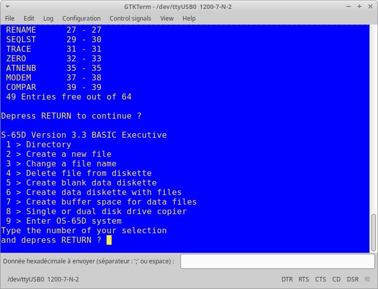
Junior DOS
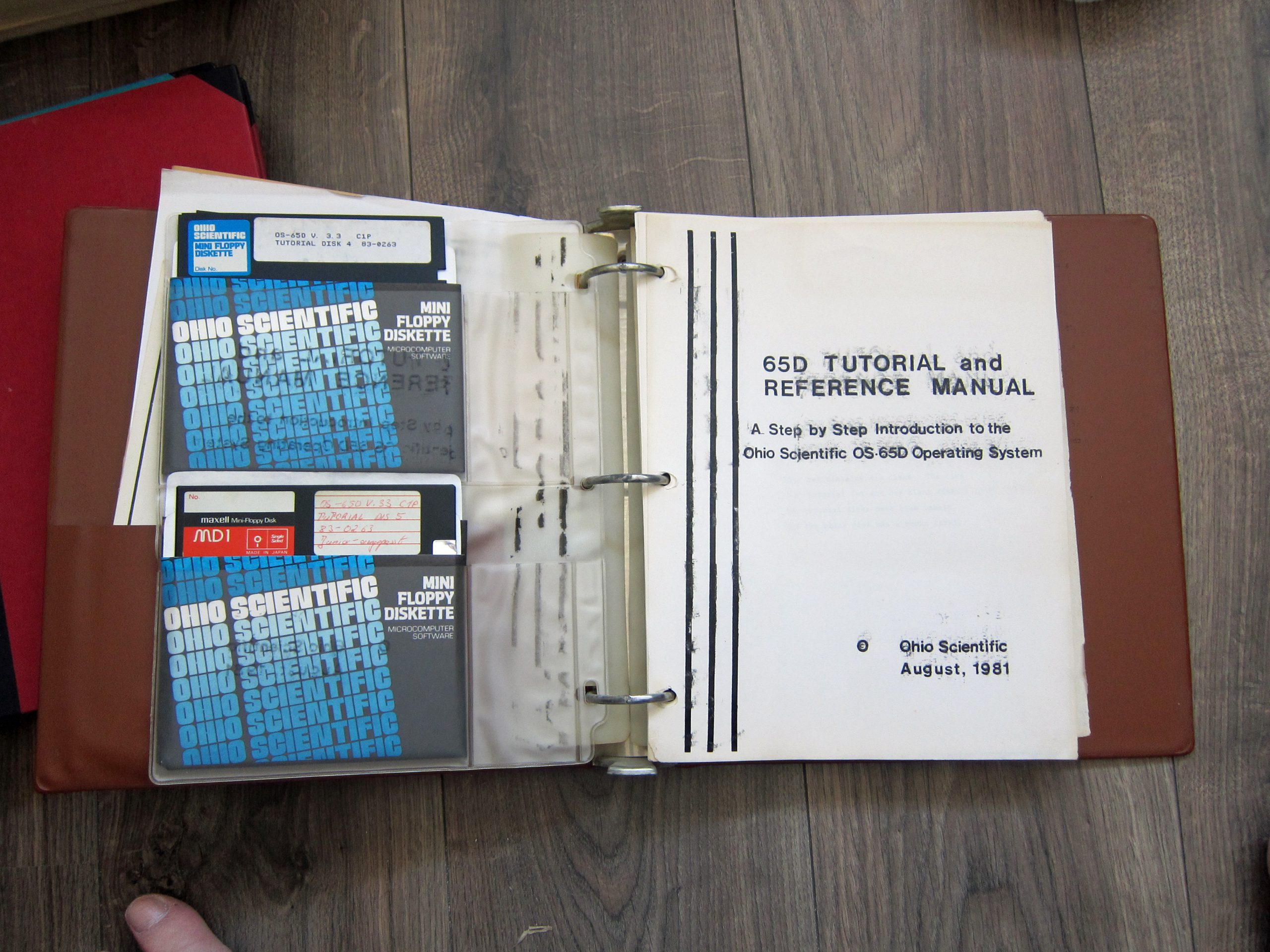
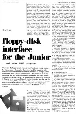
The floppy disk system for the Junior was based upon OS-65 V3D from Ohio Scientific, the interface is a clone and, since the software was for sale, a separate object.
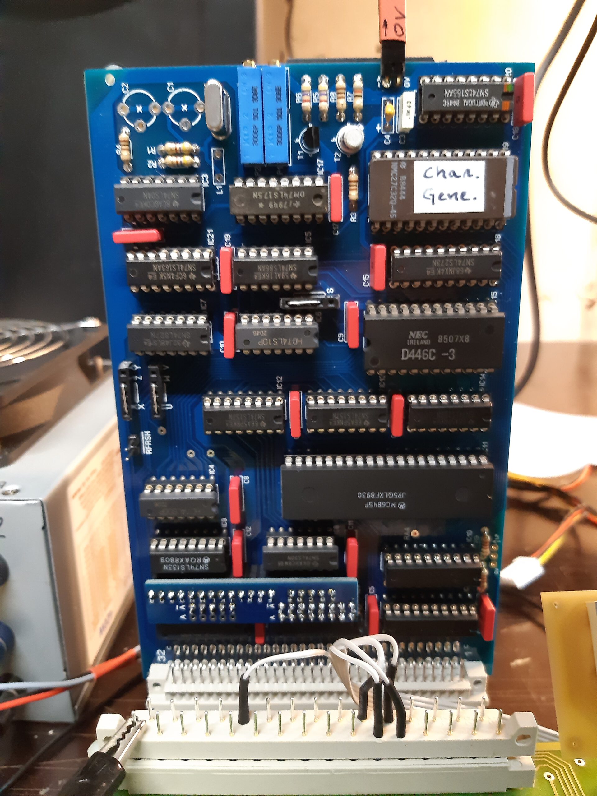
VDU board with OS65D
PMV for OS65D source checked by Philippe Roehr
PMV for OS65D ROM
See also:
KIM-1 Simulator documentation
KIM-1 Simulator
Hans Otten, Eduardo Casino, 2019- 2026, Version 2.0.0 beta
Contents
Introduction
Installatio...
DIY KIM-1 Keypad
A spare KIM-1 keypad is even rarer than a KIM-1 itself. With this guide you can build a reasonable replica of the ke...
Proton PIM-1
Gerben Voort acquired a microprocessor development system PIM-1 developed by Proton, of PC-1 fame.
Here his photos of...
PROTON Electronics: PC-1, CB80, PIM-1
PROTON Electronics, a small company from Naarden the Netherlands, led by James Post, and A.J. Kool as technical manager,...
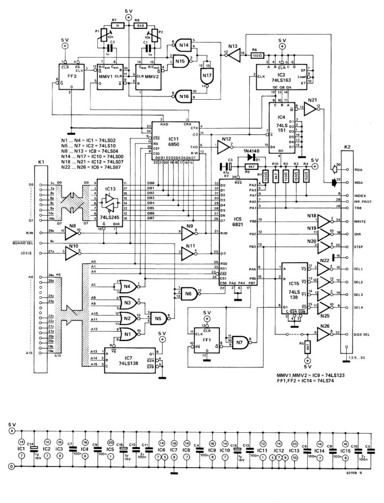
Circuit of the floppy disk interface. Not the usual circuit based upon a well-known FDC controller IC, but a simple and not so standard solution. The OS65D operating system from OSI, Ohio Scientific, knows how to handle this interface well, and just for this purpose, Elektor choose this solution.
The next page gives information on OS65D, the operating system.
See also:
KIM-1 Simulator documentation
KIM-1 Simulator
Hans Otten, Eduardo Casino, 2019- 2026, Version 2.0.0 beta
Contents
Introduction
Installatio...
DIY KIM-1 Keypad
A spare KIM-1 keypad is even rarer than a KIM-1 itself. With this guide you can build a reasonable replica of the ke...
Proton PIM-1
Gerben Voort acquired a microprocessor development system PIM-1 developed by Proton, of PC-1 fame.
Here his photos of...
PROTON Electronics: PC-1, CB80, PIM-1
PROTON Electronics, a small company from Naarden the Netherlands, led by James Post, and A.J. Kool as technical manager,...
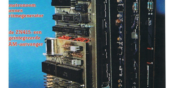
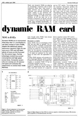
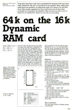
In a time when SRAM was expensive, power hungry and small it made sense to use dynamic RAM: larger, cheaper.
First in 16K format, later in 64K format.
Have a look at the Elektor Articles and Books page for a mullti-lingual overview of all publications on Elektor/Elektuur Junior and more.
See also:
KIM-1 Simulator documentation
KIM-1 Simulator
Hans Otten, Eduardo Casino, 2019- 2026, Version 2.0.0 beta
Contents
Introduction
Installatio...
DIY KIM-1 Keypad
A spare KIM-1 keypad is even rarer than a KIM-1 itself. With this guide you can build a reasonable replica of the ke...
Proton PIM-1
Gerben Voort acquired a microprocessor development system PIM-1 developed by Proton, of PC-1 fame.
Here his photos of...
PROTON Electronics: PC-1, CB80, PIM-1
PROTON Electronics, a small company from Naarden the Netherlands, led by James Post, and A.J. Kool as technical manager,...