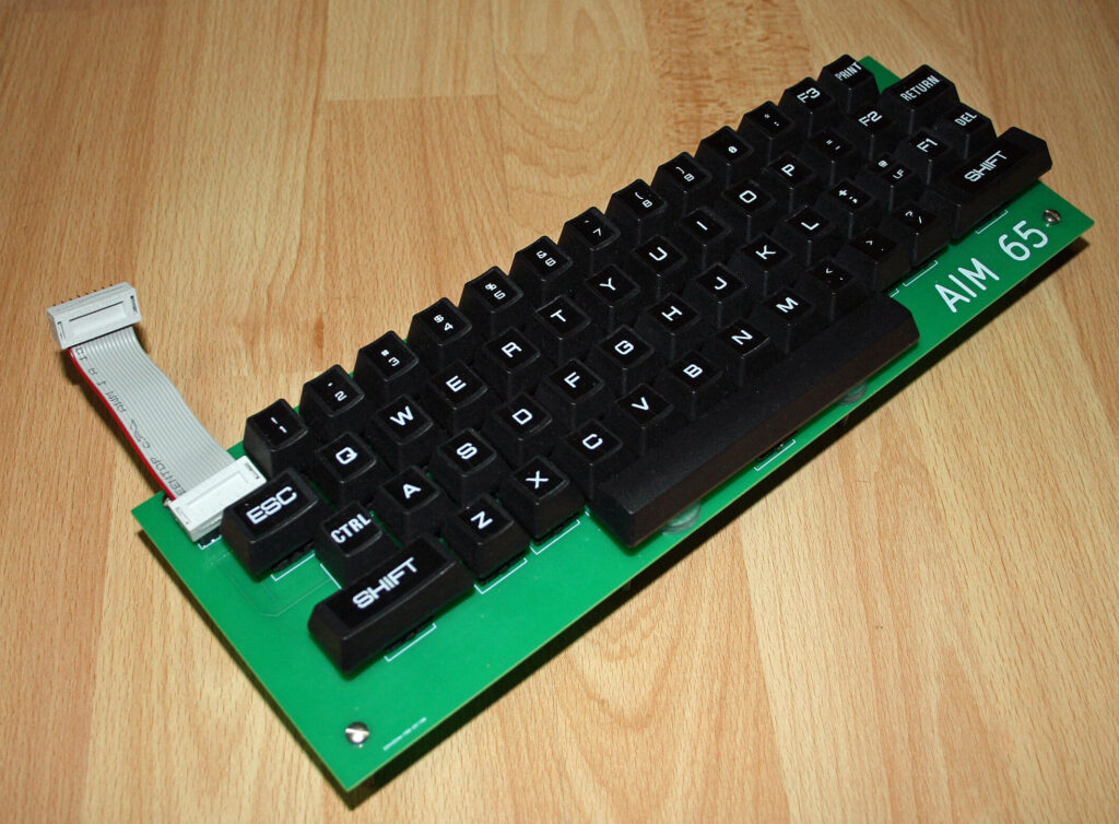
Ralf (ralf02, forum64.de) obtained a working AIM 65, alas without the keyboard.
So he designed and build one. In his own words:
Wenn ich an den Rechner 24 Volt (für den Drucker) und 5 Volt anlege, startet er schon einmal. Allerdings war leider keine Tastatur dabei. Es gibt zwar Tastatur-Nachbauten, die bei Ebay & Co für sehr viel Geld verkauft werden, aber ich dachte mir, das kann man doch auch selbst machen. Also habe ich mit KiCad eine Platine entworfen, mit Cherry MX Tastern bestückt, “blanke” Tastenkappen von Amazon draufgesetzt und mit dem Brother Etikettendrucker beklebt.
Translated:
When Ralf connected the 24 V (printer) and 5 V, the system started. But the keyboard was missing. Though there are keyboard replicas on ebay , costing quite a lot of money, I decided to build one myself. Kicad for the PCB, Cherry MX keys, blank keycaps and a Brother labelprinter for the lettering.
The result is a quality keyboard that fits the AIM 65 very well. See here the page with photos and design.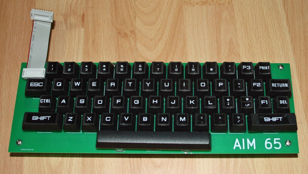
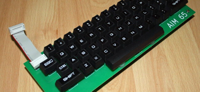
Ralf (ralf02, forum64.de) obtained a working AIM 65, alas without the keyboard.
So he designed and build one. In his own words:
Wenn ich an den Rechner 24 Volt (für den Drucker) und 5 Volt anlege, startet er schon einmal. Allerdings war leider keine Tastatur dabei. Es gibt zwar Tastatur-Nachbauten, die bei Ebay & Co für sehr viel Geld verkauft werden, aber ich dachte mir, das kann man doch auch selbst machen. Also habe ich mit KiCad eine Platine entworfen, mit Cherry MX Tastern bestückt, “blanke” Tastenkappen von Amazon draufgesetzt und mit dem Brother Etikettendrucker beklebt.
Translated:
When Ralf connected the 24 V (printer) and 5 V, the system started. But the keyboard was missing. Though there are keyboard replicas on ebay , costing quite a lot of money, I decided to build one myself. Kicad for the PCB, Cherry MX keys, blank keycaps and a Brother labelprinter for the lettering.
The result is a quality keyboard that fits the AIM 65 very well.
Ralf gave me permission (thanks!) to publish the photos and gerbers of the PCB.
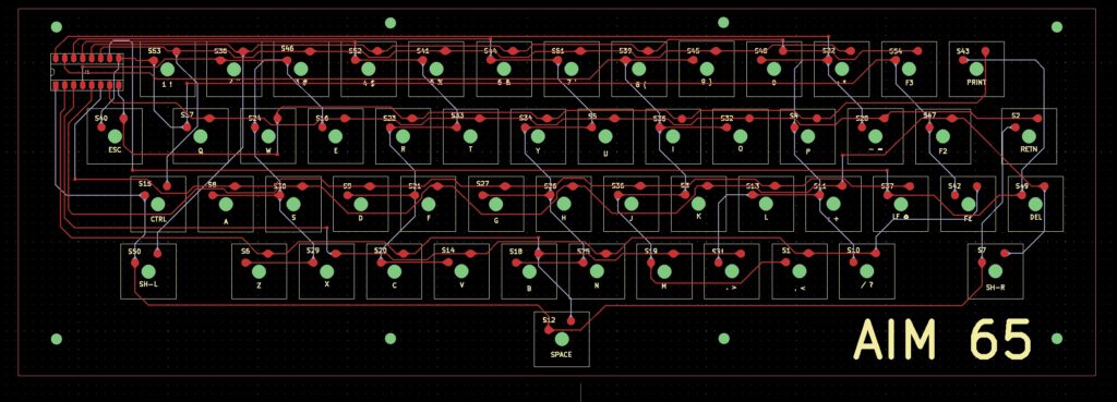
Here the archive with the gerbers of the PCB.
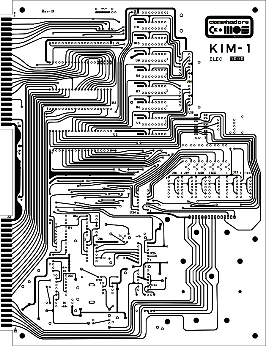
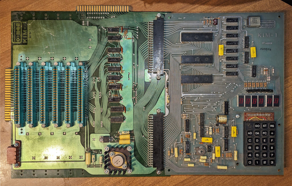
Eduardo Casino has designed with modern tools, like Kicad and image software Inkscape a PCB for the KIM-1 which is as close as he could get to a Rev D.
Based upon images on the Revisions pages on this site.
On this forum64.de thread he published the design, and made all available on his github pages.
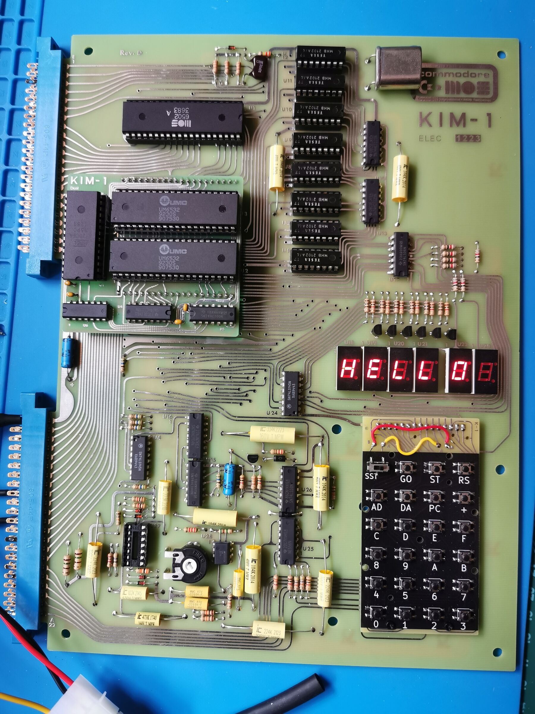
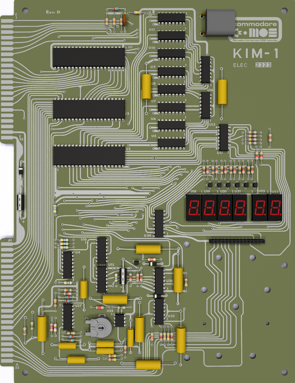
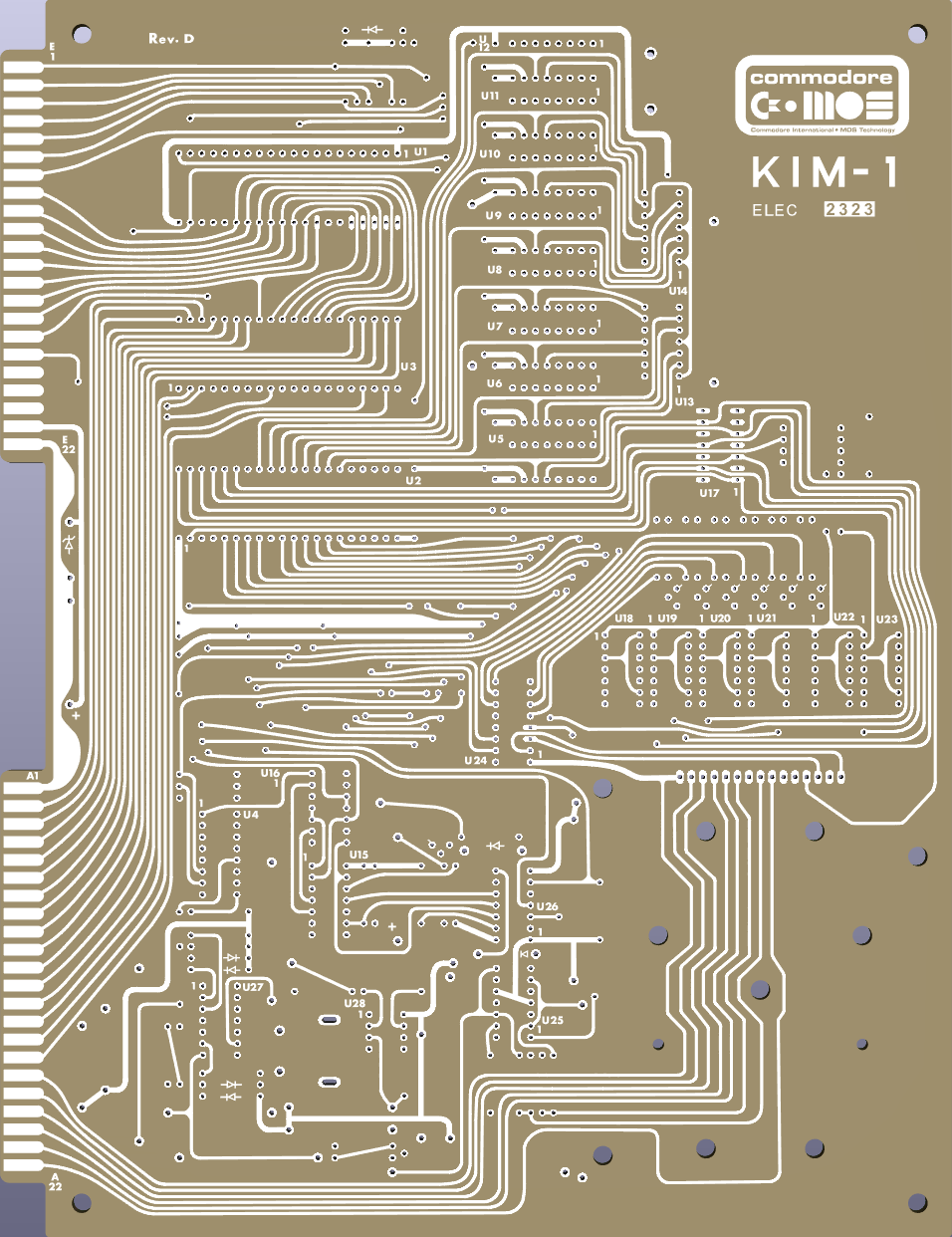
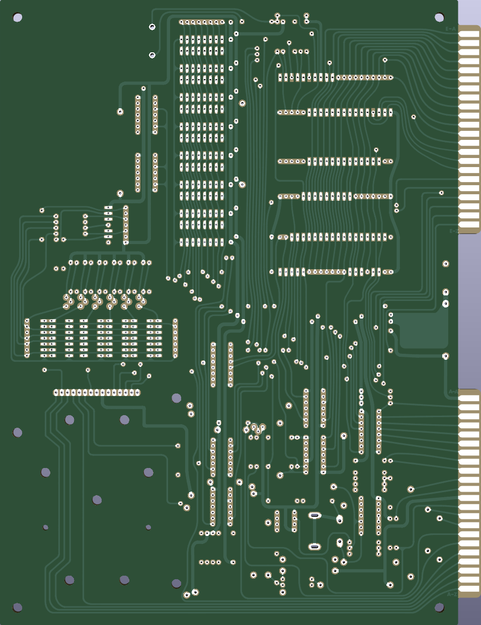
The PCB is an exact PCB replica of the KIM-1. It therefore requires 6530-002 and -003 RRIOTs, which are not available anymore (or use the Retrospy Technologies 6530 replacement boards).
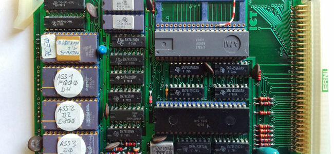
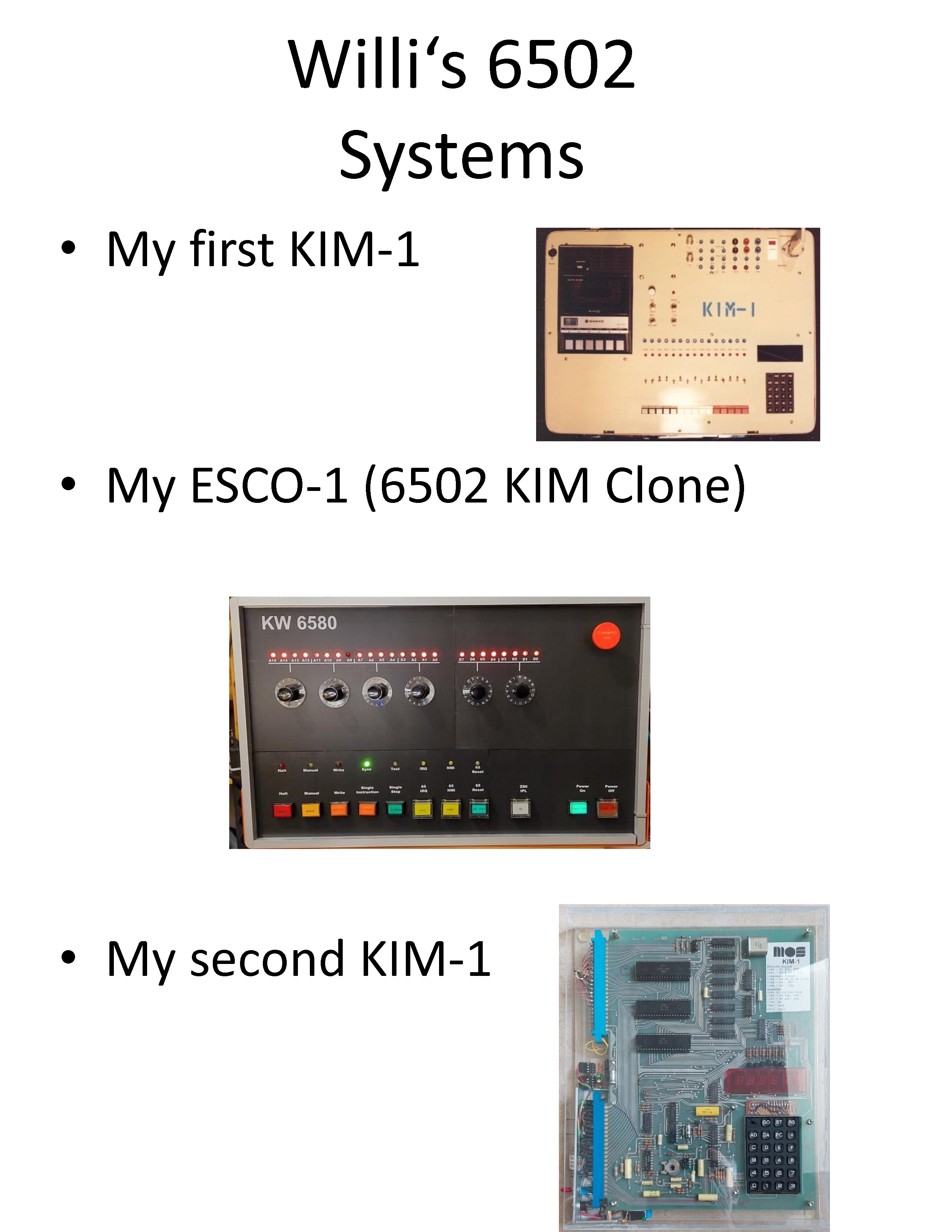
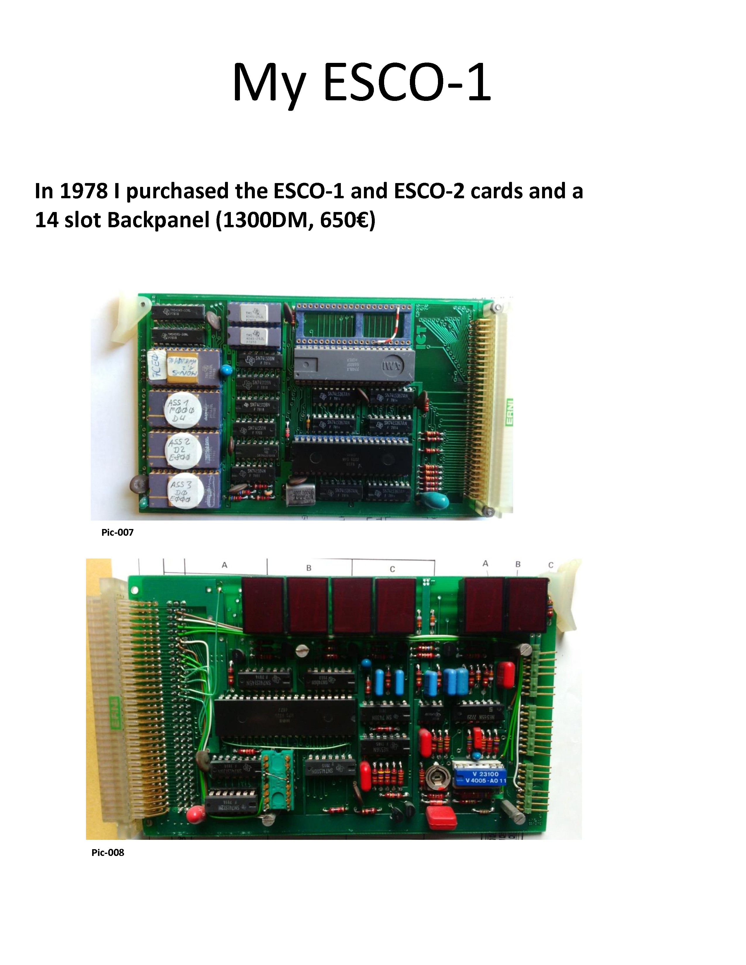
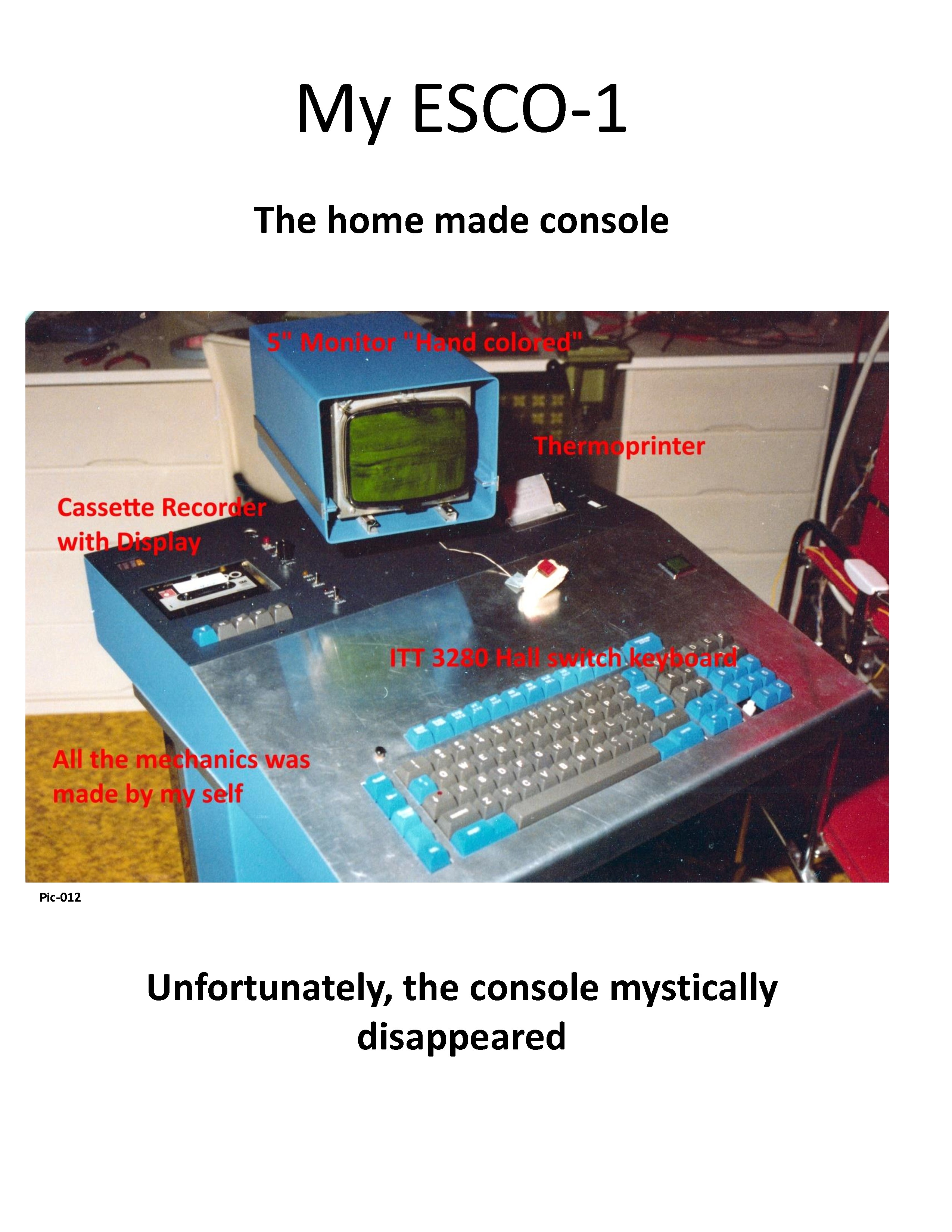
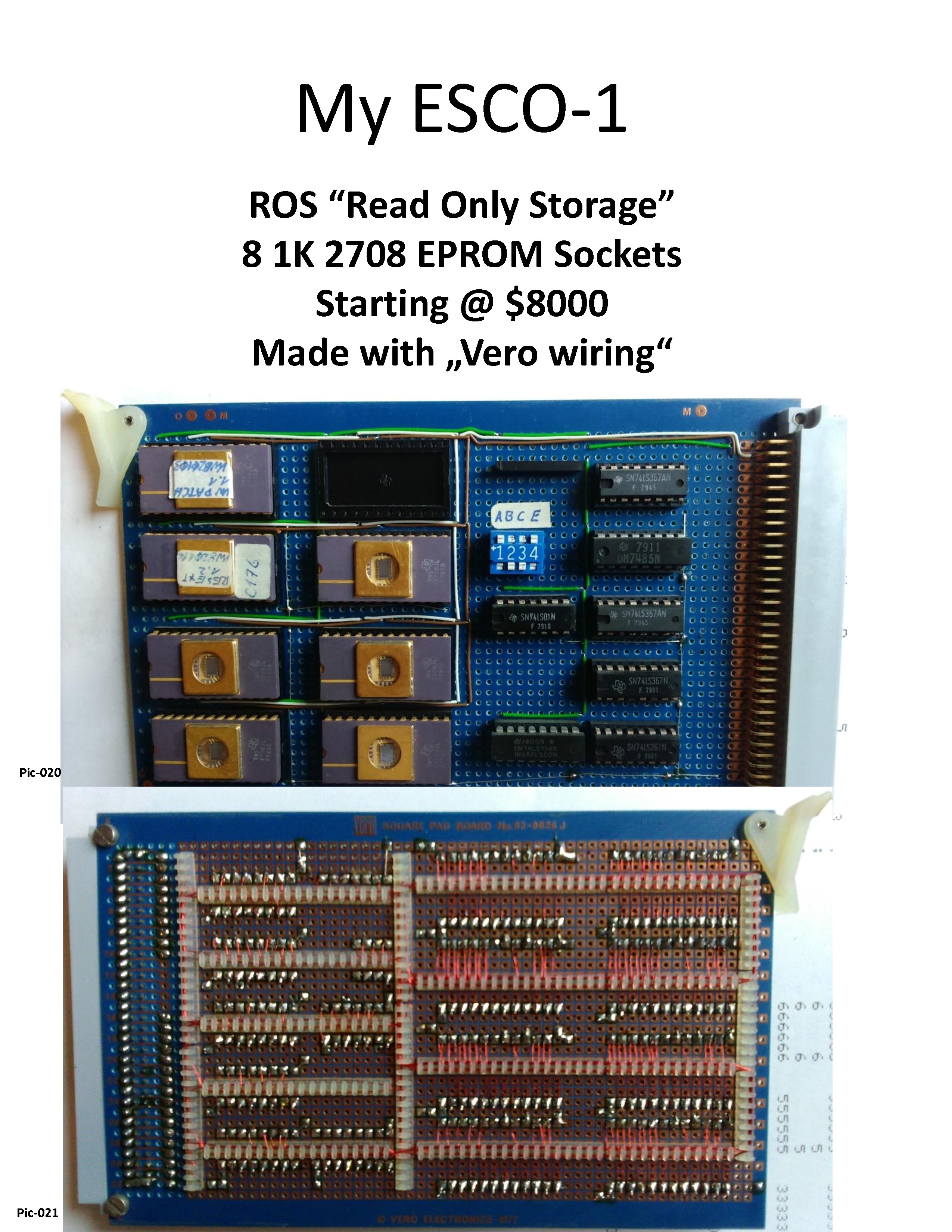
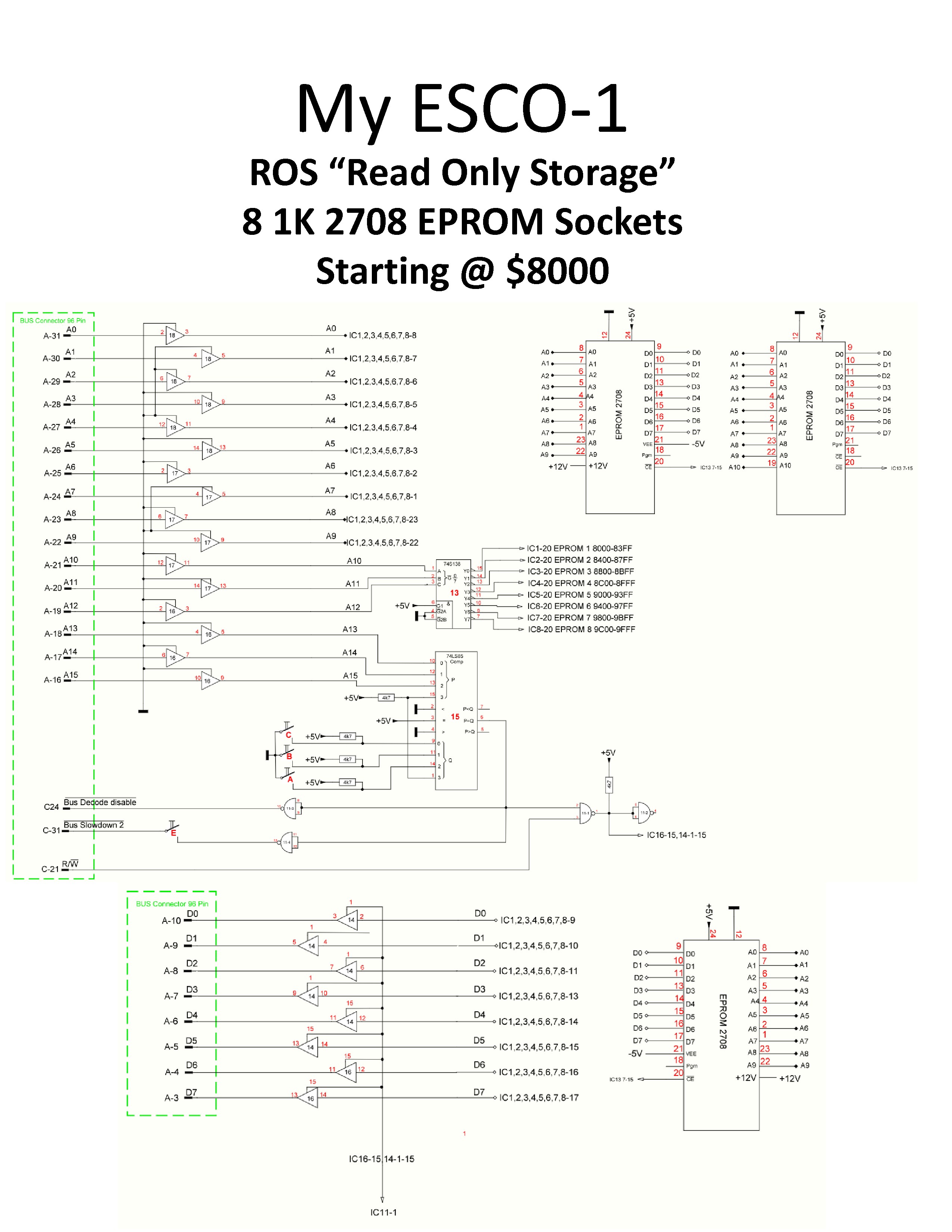
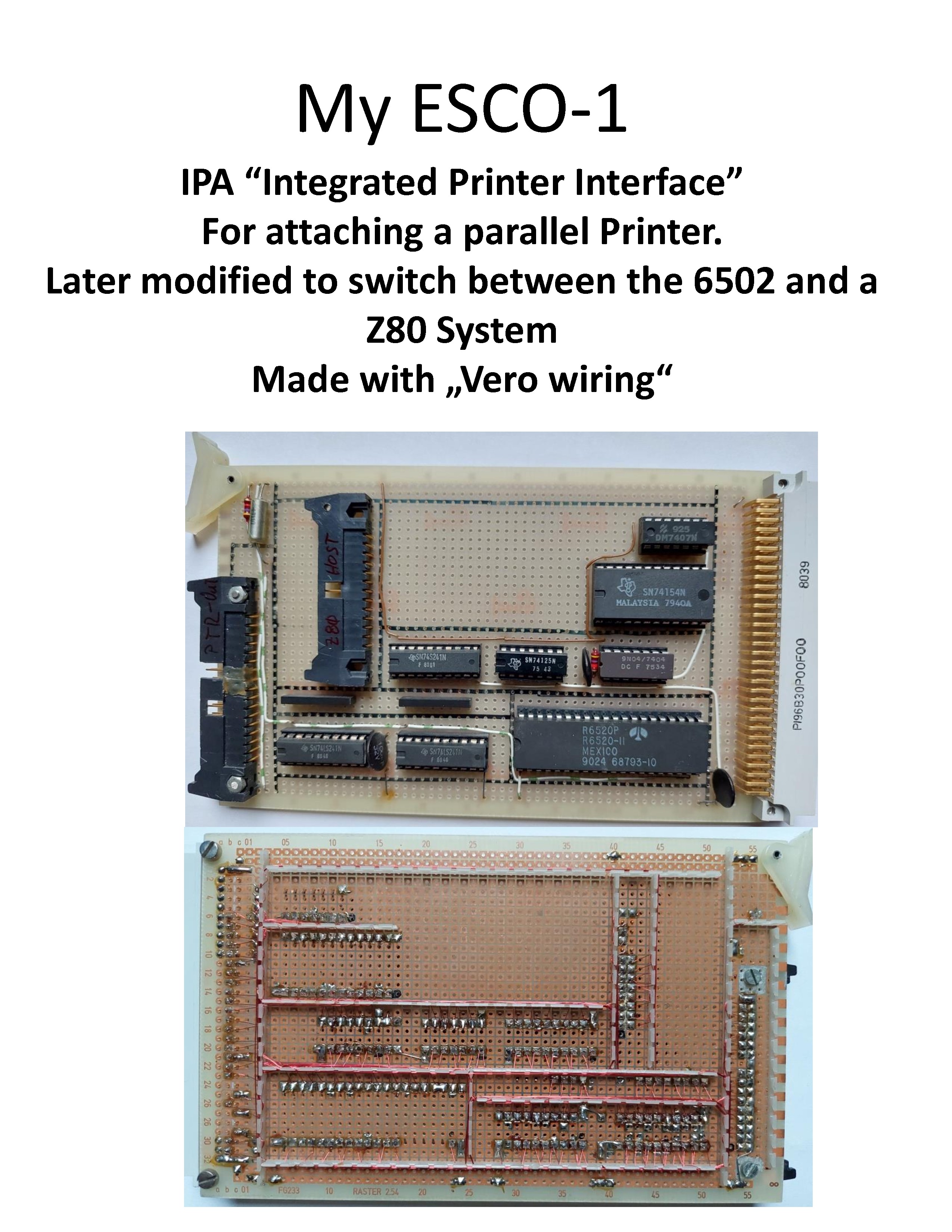
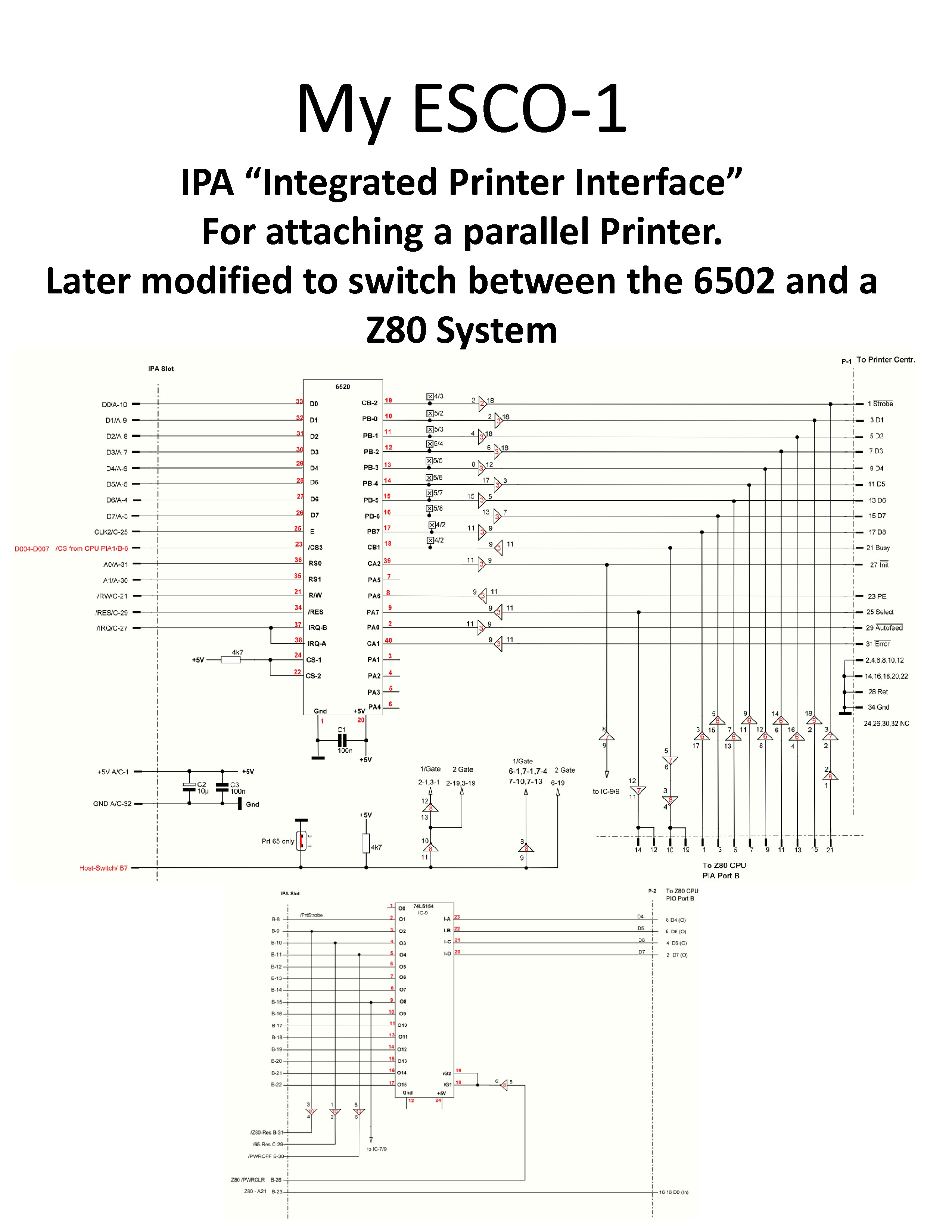
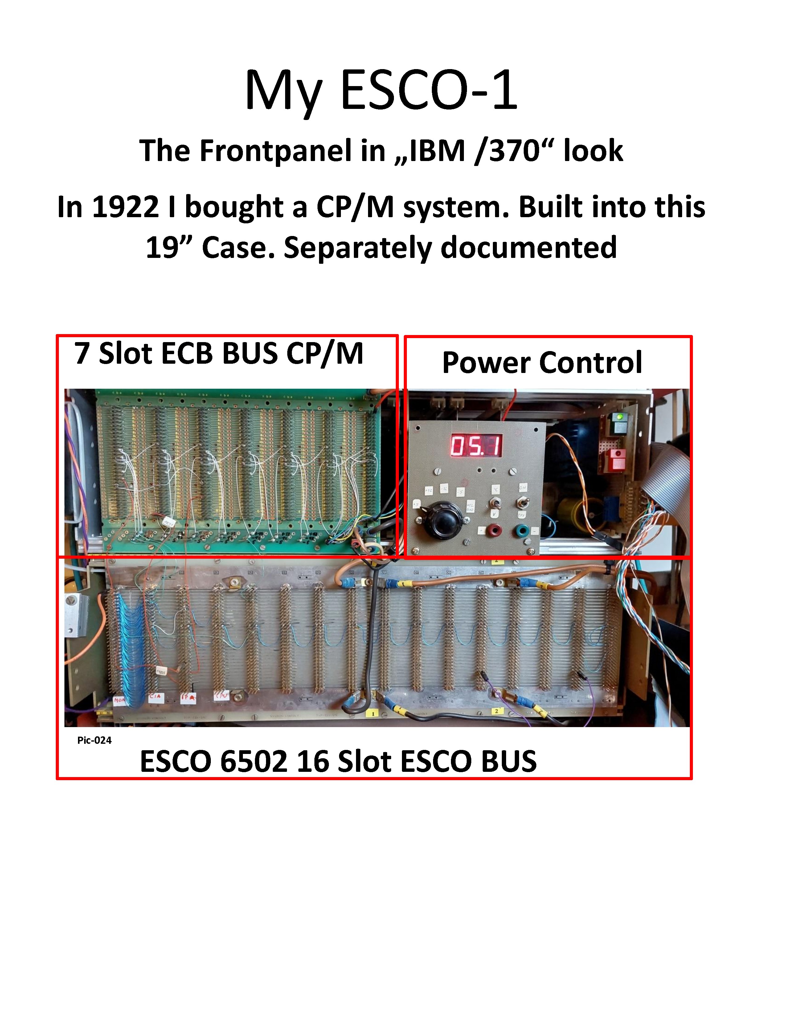
User wikokim on the forum.classic-computing.de bought this system in 1978/79. And published the following documents and ROM dumps.
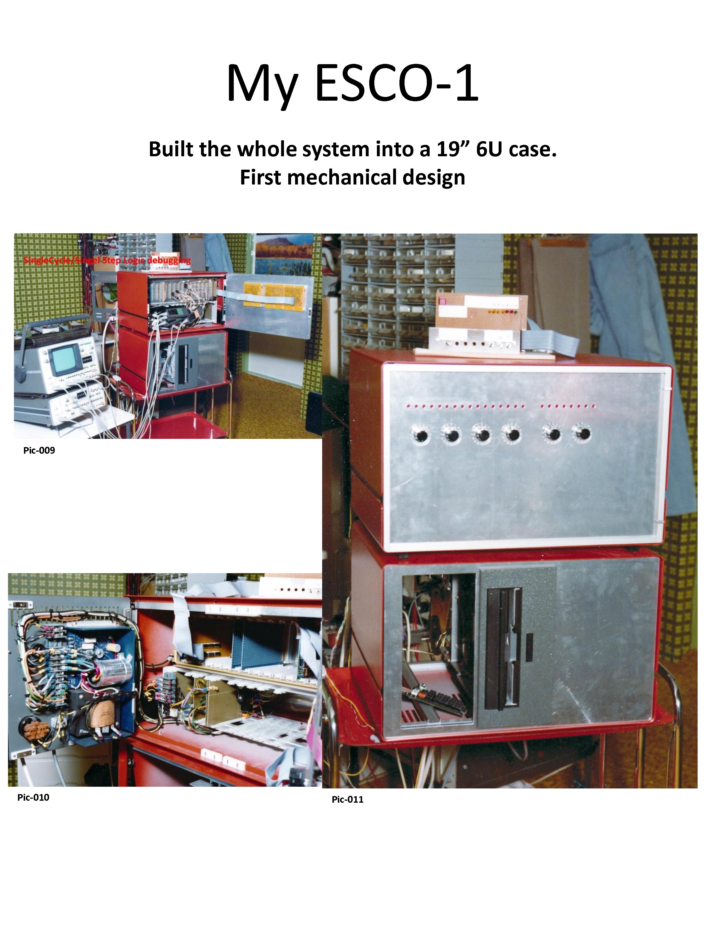
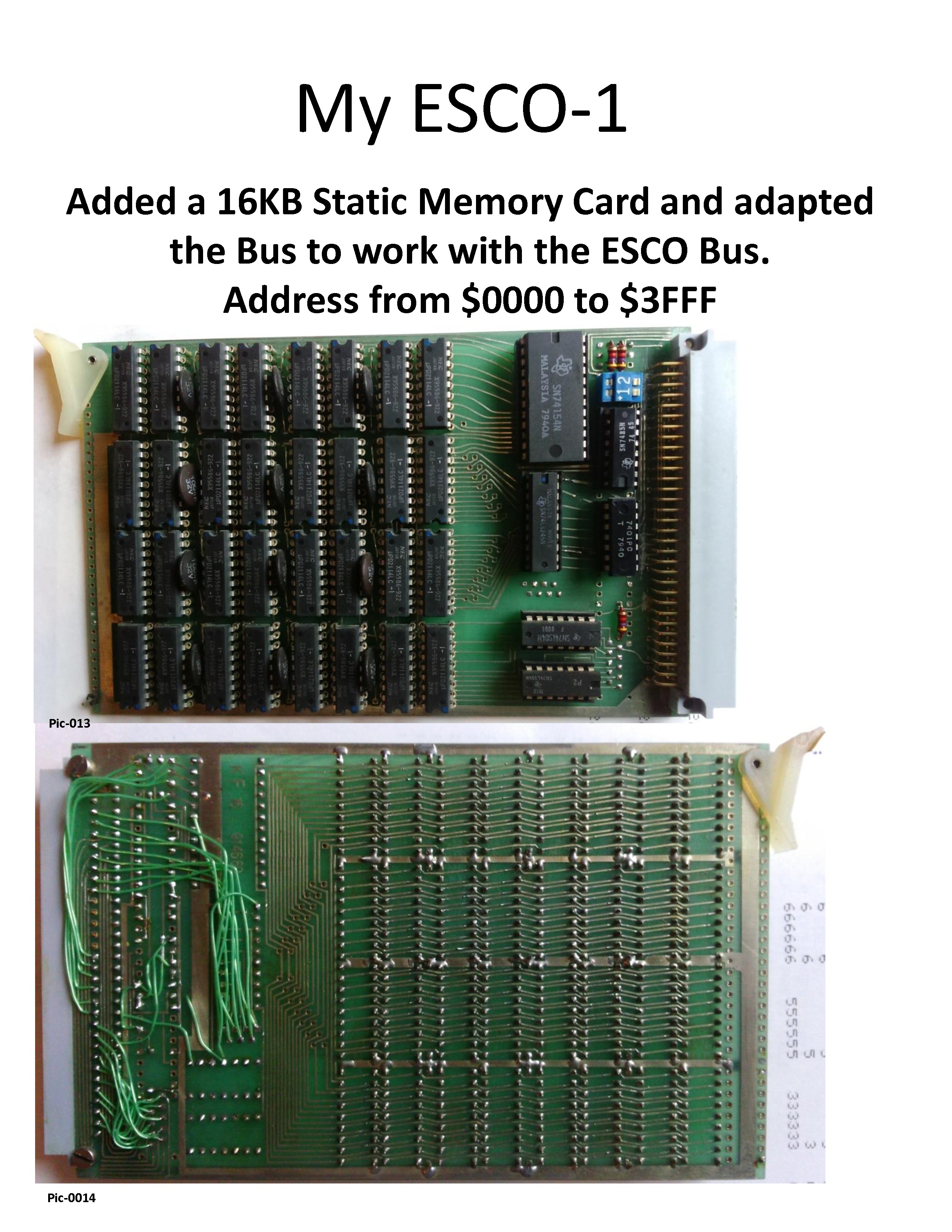
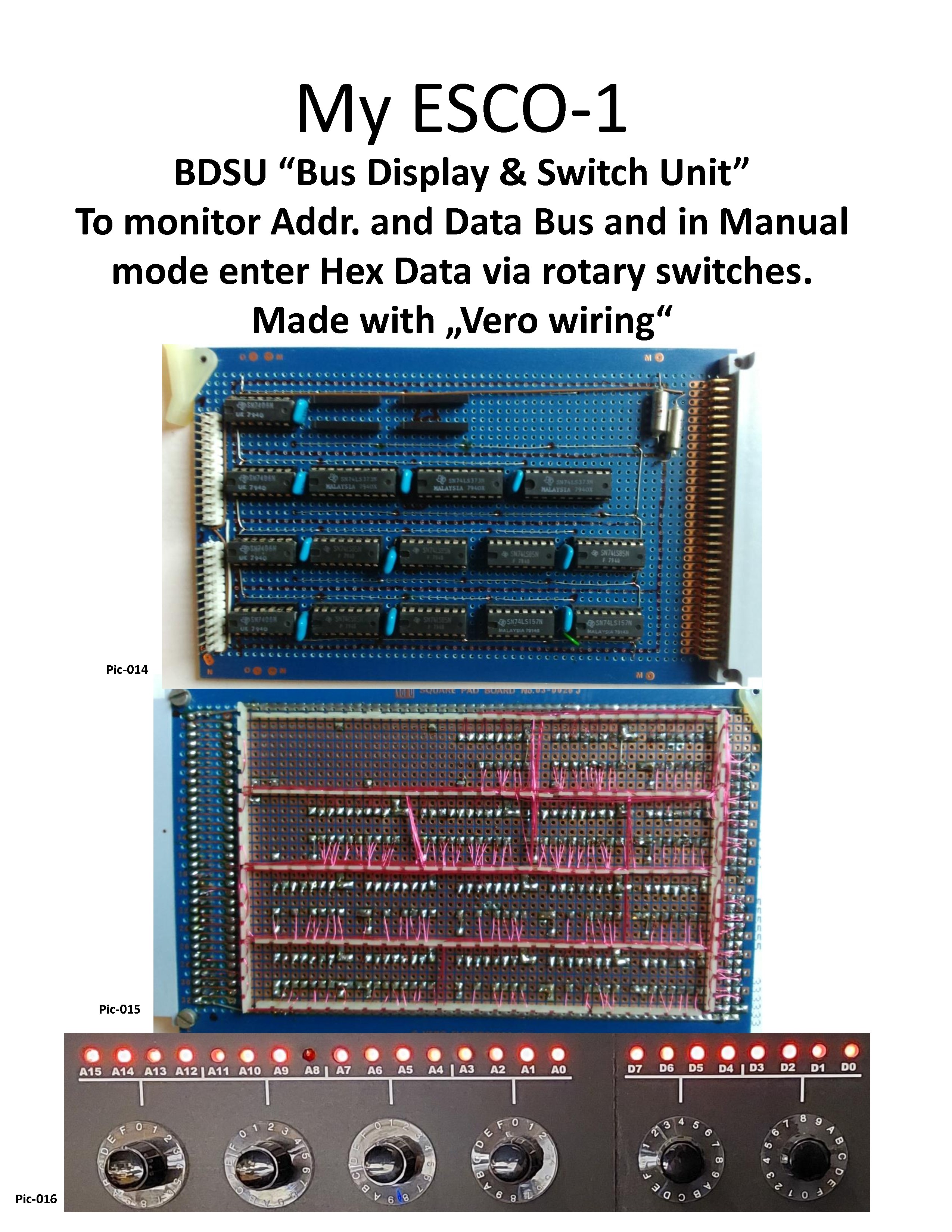
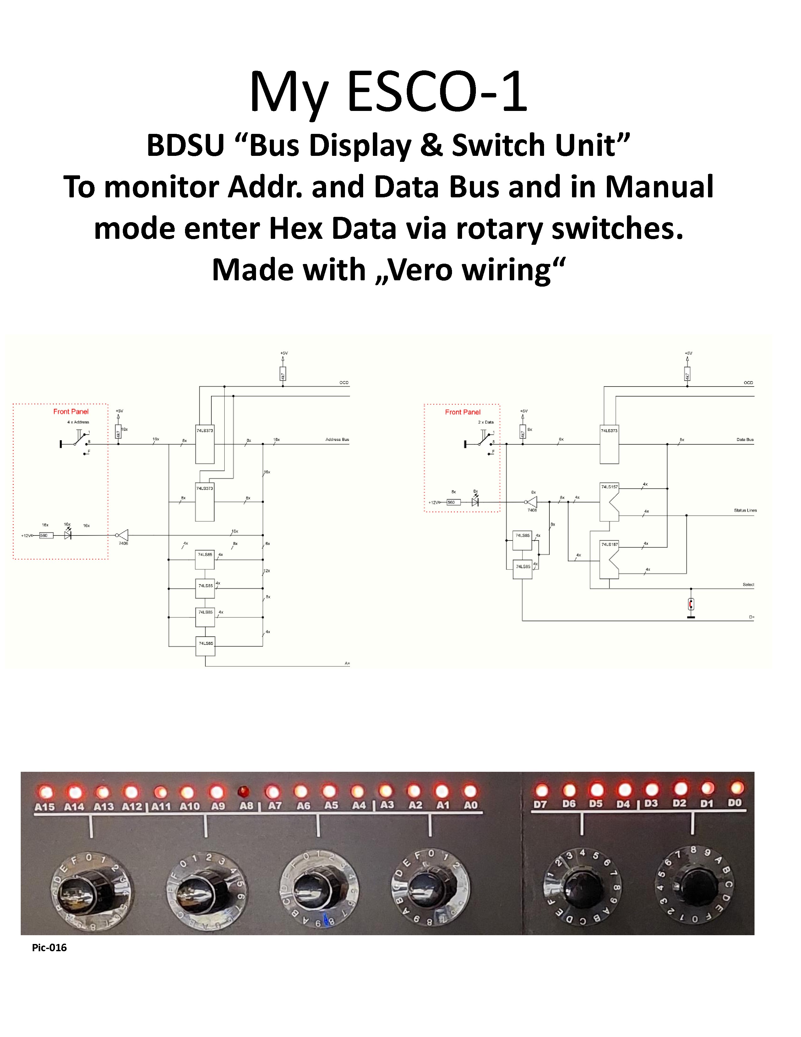
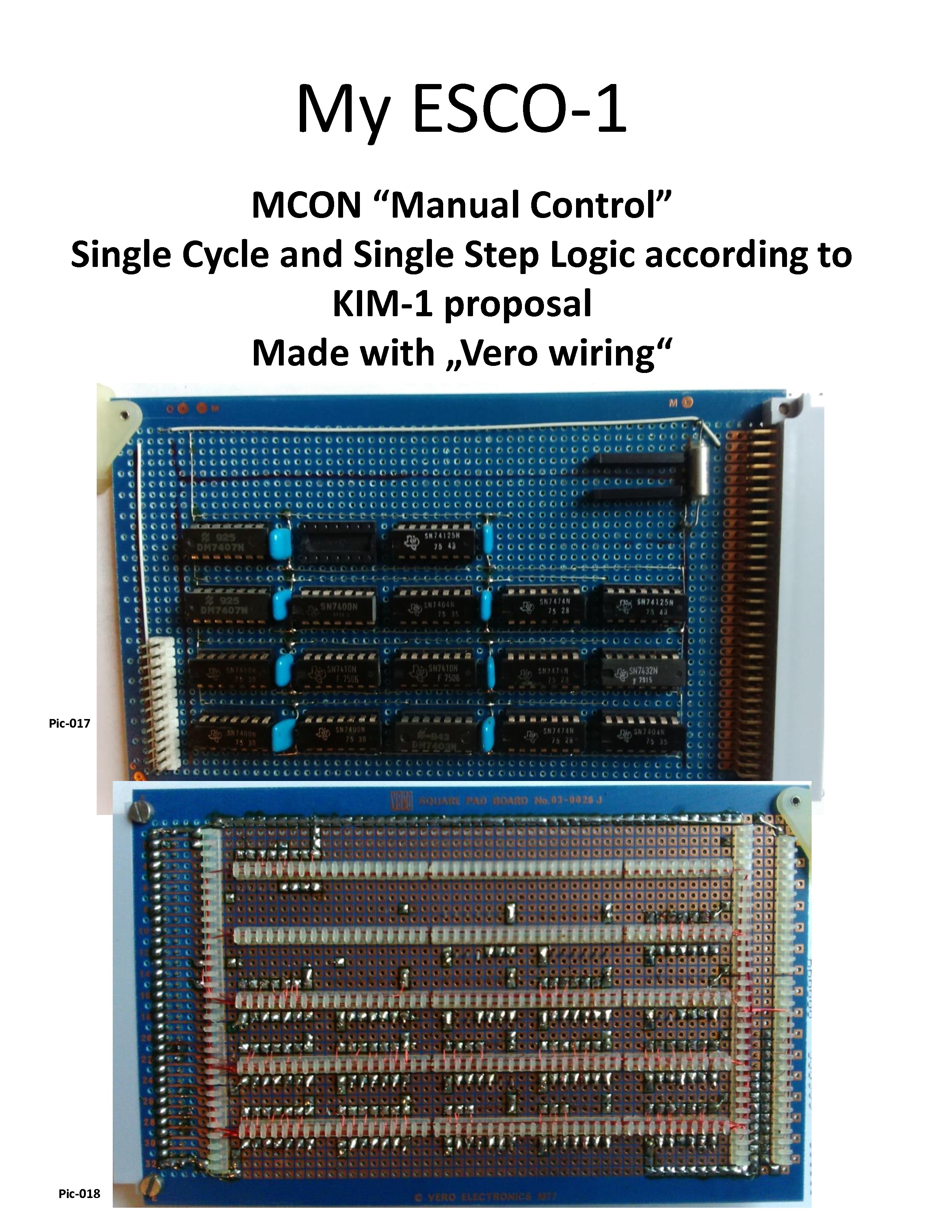
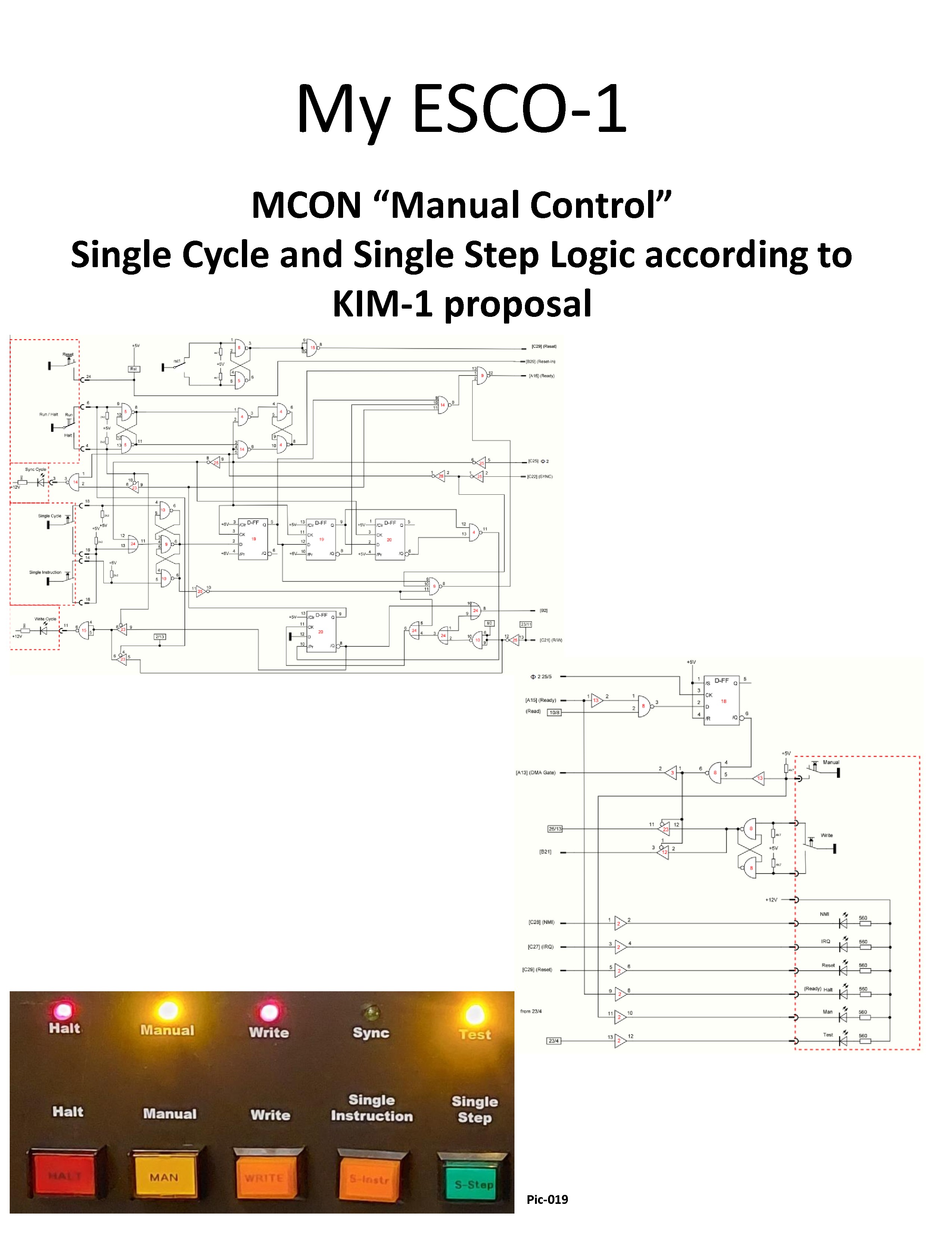
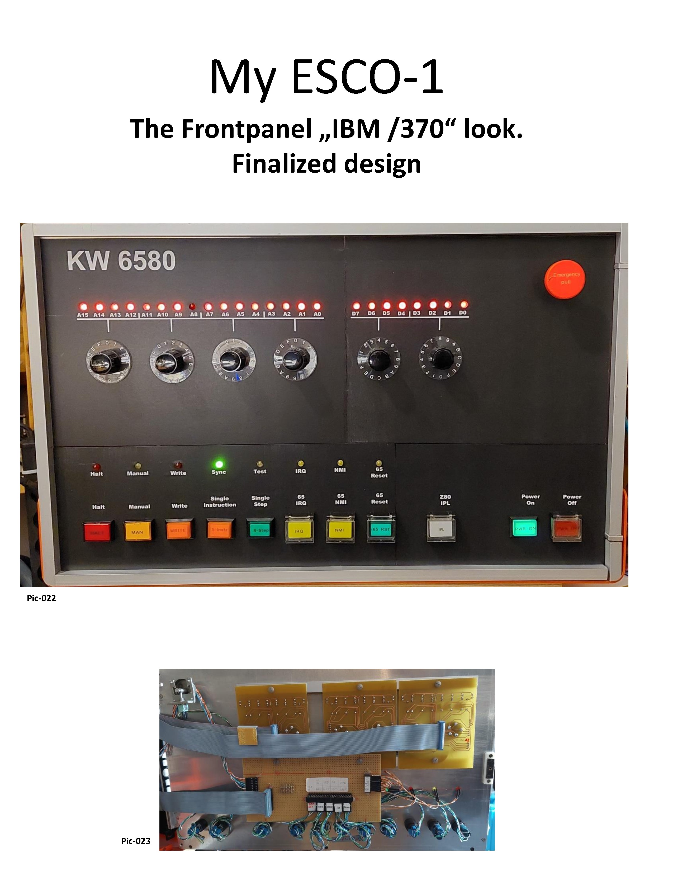
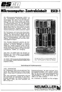
The ESCO 1 was DM 520, the ESCO Monitor DM 460 (German Marks). The backplane was DM 190. He added a 16KB Static Memory Card from KF (?) and modified the Card to work with the ESCO Bus. He also made a LED based Bus Monitor including the KIM-1 based Single Cycle /Single Step Logic.
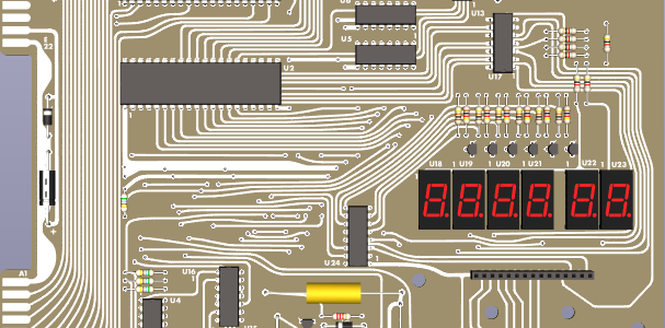
ESCO stands for Europa Single Board Computer.
The ESCO system was desigend and sold by the firm Neumüller. The firm still exist, though they remember nothing about the ESCO.
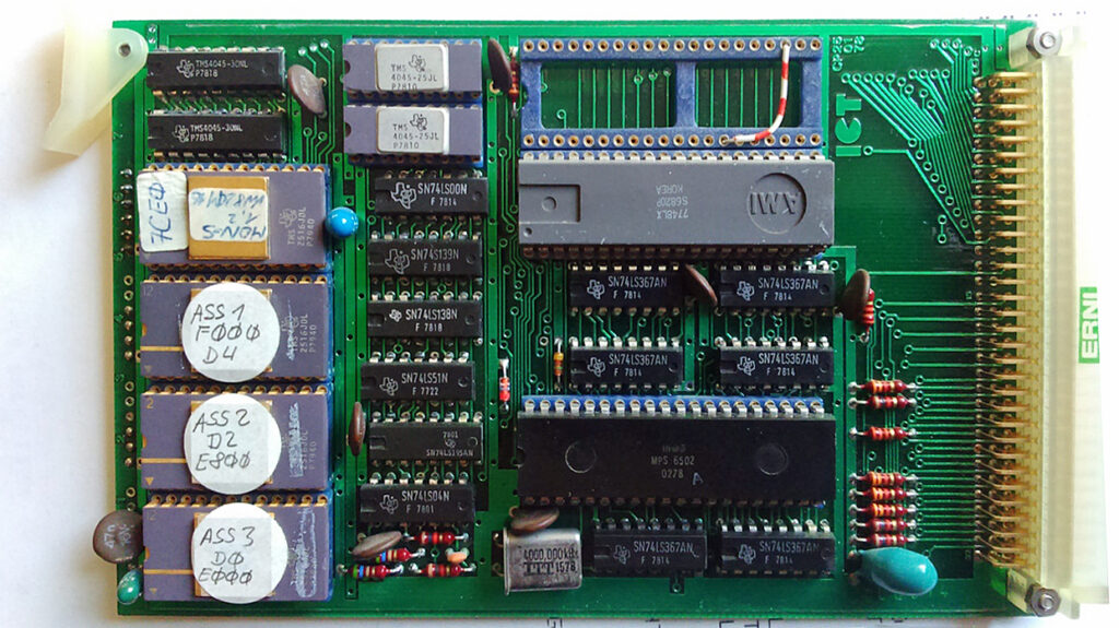
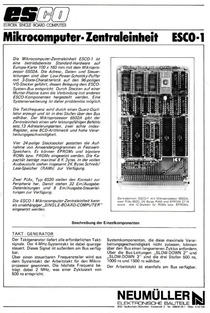
The ESCO SBC has:
- 4 SRAMS TMS4045 makes 2K RAM
- several address decoders, including 145 like the KIM-1
- A 4MHz crystal, divided to 2 MHz or less MHz.Since the 6502 is the 1 MHz NMOS part, likely 1 MHz
- the 6820 is a PIA, the empty slot is for a second PIA
- 4 IC sockets for2516 EPROMS, here with monitor and an Editor/Assembler
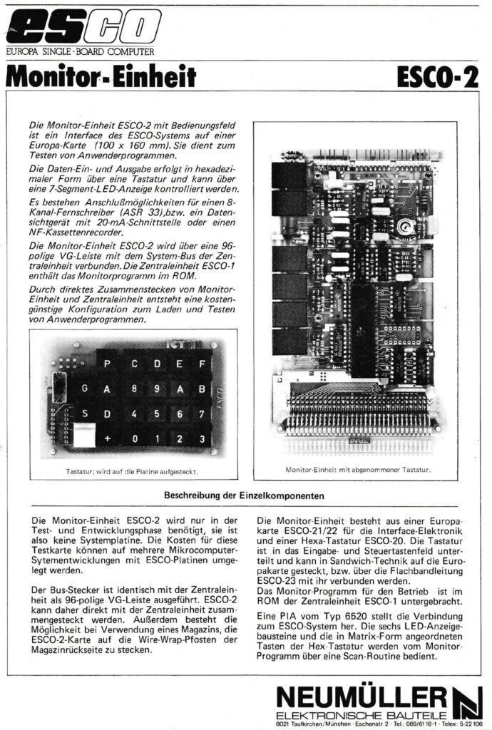
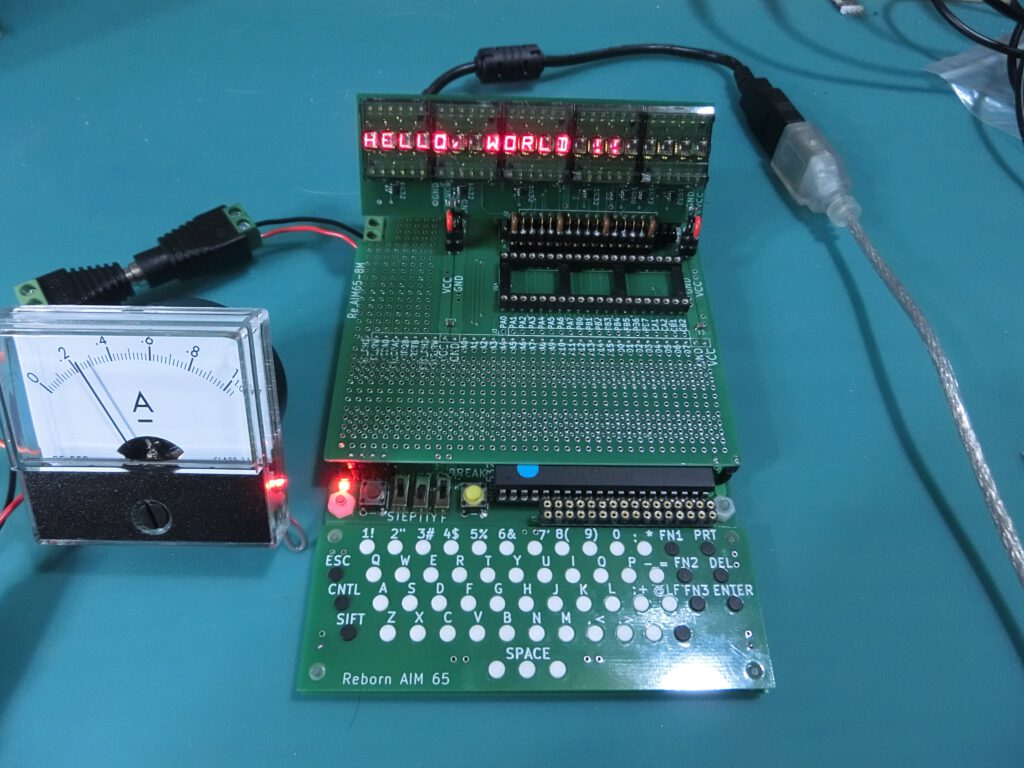
The optional ESCO monitor, consisting of a EuroCard and a separate keyboard PCB, with the usual hex keybaord, 6 seven segment LED displays, audio cassette interface, and a serial 20 mA TTY interface.
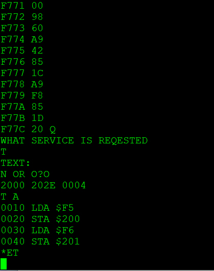
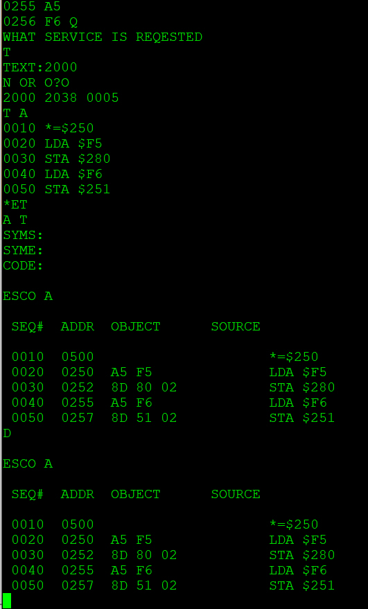
Texteditor and Assembler in action. Started Texteditor with “Q” (home made ESCO Monitor extension q $8000). Then “T” to start Texteditor. “TEXT:” entered 2000 (start of texteditor Storage Area). “N Or O” for new or old Text. Entered “O” , “2000 2038 0005” Text Start @2000 to 2038 5 Lines entered . “A T” Starts Assembler 1 Pass to Terminal (SYMS, SYME, Code left default) . “D” Starts pass 2 to terminal.
Available documents and ROM dumps:

