post

The Computerist Hardware

The Computerist was a company founded by Robert M. Tripp.

On this page information on the PLUS hardware for KIM-1, AIM 65, SYM-1.. Updated April 2022 with contributions by Friedrich Hofmann.

Memory PLus van Dirk Dral, met 8K Basic in EPROM.

MICRO the 6502 Journal

Archive of the magazine Micro here.

From apple2history.org description of MICRO 6502 Journal:
Robert M. Tripp got his start with computers in 1960 as an undergraduate in an unrelated field. He found the computer programming so interesting that he became a programmer in 1969, and started with the 6502 microprocessor in 1976, initially with the KIM-1 trainer sold by MOS Technology. He started a business, “The COMPUTERIST”, and sold the KIM-1 computers, as well as software and accessories for it. He started a magazine under the umbrella of his business, and named it Micro. It began publication in October of 1977, and was released on a bimonthly basis initially, going monthly in February of 1979. The first three issues were printed using his KIM-1 and he did the paste-up for the magazine on his kitchen table. He later began to use a local publishing company to create the magazine. By early 1980 the publisher name had changed to MICRO-INK, Inc.

The magazine covered the 6502 microprocessor (and later the 6809) in all the various computers that used it, including the KIM-1, the AIM-65, the C1P, the Commodore PET, the Ohio Scientific, the Atari 800, and, of course, the Apple II. It was an excellent source for machine level code for the 6502, eventually including more and more articles that applied specifically to the Apple II. Ultimately, about half of the articles in each issue dealt with the Apple II.

Many general-purpose machine language articles appeared in its pages, such as “Improved nth Precision” (code optimization for the 6502), “Precision Programming”, and “Computer Assisted Translation Of Programs From 6502 to 6809″. They also carried do-it-yourself hardware articles, such as “C1P To Epson MX-80 Printer Interface”, “PET/CBM IEEE 448 To Parallel Printer Interface”, and “Apple II Digital Storage Oscilloscope”.

Hardware by The Computerist

The Computerist, led by Robert Tripp, not only sold software like MicroChess,  published the Micro Magazine, also designed and sold hardware.

The Dutch company, Ing. Bureau Koopmans (a one man company, active in the early years with KIM-1, OSI Scientific and such) represented The Computerist in the Netherlands, and he showed me in 1979 some of the Plus hardware series for the KIM-1, SYM-1 and AIM-65 systems:
– MEMORY PLUS: 8K RAM, 8K ROM, VIA 6522, 2716 EPROM programmer
– Proto Plus, a DIY board
– VIDEO PLUS, a glass teletype video card

I did a review of the Memory Plus in May 1979, see also the dutch magazine Radio Bulletin page.

PLUS Hardware

A range of hardware was developed and sold by the Computerist, under the brandname PLUS.


Motherboard Plus

A backplane for KIM-1/SYM-1/AIM 65. Accepts the Plus boards described below.

Memory Plus

The MEMORY PLUS board is a RAM/ROM expansion board for  KIM-1, SYM-1 or AIM65. Made by the The Computerist.

With up to 8k of RAM, 8k of (EP)ROM and the ability to program EPROMs (2716) this was quite the must have upgrade for anyone who could afford it.

Here The Manual in HTML format, original OCRed by Lee Davison, corrected and enhanced with Appendix A Circuit Diagram and Application Note #1 by Hans Otten.

Scanned by Dirk Dral, high quality scan.

And here the MEMORY PLUS manual in PDF format, Appendix A, the circuit diagrams  foldout Application Note #1 is now included, added by Hans Otten.

How to decode the 8K RAM in 4K space, an article from Micro July 1979, for AIM 65 and SYM-1 

Video Plus

VIDEO PLUS is designed to work with the KIM-1, SYM-1 and the AIM 65 computers. It offers:

  • Up to 4K  display RAM and 2K Programmable Character generator
  • 2K EPROM
  • 6845 CRT controller
  • ASCII keyboard interface
  • Composite monochrome video PAL or NTSC

The following documents are available:

Video PLUS II

Video PLUS II is an updated Video PLUS, a Versatiel Video Expansion Board, with:

  • Programmable Screen format
  • PRogrammable Character Generator
  • Uo to 4K Display Memeory
  • Supports ASCII Keyboard
  • Stand-Alone Option
  • AIM/SYM/KIM Software
  • 6845 video controller, 6522 VIA, RS232

The following documents are available:

PROTO PLUS II

The PROTO PLUS II is a board to interface digital logic to a KIM-1, SYM-1 or AIM 65. A large breadboard area is available.

The board has the standard KIM-1 44 pin edge connector. A power regulator for 8V to + 5V is on the board.

The board has  address, data bus and signal bus buffering and address decoding for tom select a 8K page in memory and kIM-1 8K decoding. 3 gates of a 74LS32 is available for general use.

Here the PROTO PLUS II manual, with circuit diagram.


DRAM Plus

DRAM Plus is a Multi-purpose Expansion Board for AIM 65/SYM-1/KIM-1 with

  • 16/32K dynamic RAM
  • 8/16K EPROM 2716/2516/2732/2532/2332
  • I/O Ports and Timers VIA 2x 6522
  • Prototyping Area
  • EPROM Programmer

DRAM PLUS manual, includes circuit diagram and software


K-1002 8 bits DAC
An 8 bits DAC. For the PET userport, easily adapted for other 6502 systems.
Hardware K-1002 manual includes circuit diagram

Files for the VIDEO and PROTO PLUS: Thanks to Dave Colglazier at Original Woodworks.

Video PLUS II and DRAM PLUS: thanks to Friedrich Hofmann

Micro-KIM

The Micro-KIM is a SBC designed and built by Vince Briel. First sold in 2007 and alas not available anymore.
Based upon the ideas of Ruud Baltissen how to replace the 6530 with a 6532, it was the first KIM-1 clone that was running the unmodified KIM-1 ROM.

Manuals, circuit diagrams, single step fix, tape devices, support Cd images
Photos
Videos


Specifications

  • 6502 CPU running at 1Mhz
  • 2K EPROM replacing built in ROM on 6530s
  • 5K RAM using the KIM-1 memory map
  • RS232 interface made to work with TIM built in KIM-1
  • Single-Step mode for debugging
  • debounced RESET and STEP switches
  • 40 pin header for future expansion
  • Expansion board for expansion connector with four slots available
  • 32K RAM card
  • Second 6532 board
  • The I/O of the 6 digit display and keyboard are memory mapped exactly like the KIM-1 for full program compatibility

See the KIM-1 page for more KIM-1 info and programs.

First impressions

  • It really feels like a KIM-1. Smaller, but just as simple to operate. Easy to connect a serial RS232 (USB) cable and connect to a terminal program. Minicom on Linux, Realterm on Windows e.g., no high demands on terminal emulation, just plain simple teletype at 9600 baud or less and the ability to capture output to a textfile or send a text file via the terminal
  • No cassette port. This means the programs with real nostalgic value like the editor/assembler Micro Ade will not have much sense.
  • Second 6532 is an option(though the 6530-002 and 003 ROM is present!).
  • 32K RAM extension option. Yes, this makes the machine worthwhile! Now you can run KB9 Microsoft Basic or otehr KIM-1 software.
  • Some small mistakes are on the version 1 Rev 0 board, fixed in the later version rev 1, this needs three hardware fixes to be made, so I have to get the soldering iron into action. Simple fixes, see below.
  • Loading programs via the serial interface by sending a text file in papertape format is slow. But it works! Fun to test all those KIM-1 programs. KIMTAPE and KIMPAPER help a lot here also look at the 8 bit hex file conversion program there.

Tested programs

Most of the First Book of KIM programs work. Some require the presence of the second 6530 (6532 here).
See the KIM-1 software and manual pages. Also see the photos section for TinyBasic and KB 9 Basic.

See the PC utilities page for papertape and other conversion utilities.

Memory map

Micro-KIM KIM-1
$0000-$03FF 1024 Bytes of RAM $0000-$03FF 1024 Bytes of RAM
$0400-$07FF 1024 Bytes of RAM $0400-$07FF Optional Memory Area
$0800-$0BFF 1024 Bytes of RAM $0800-$0BFF Optional Memory Area
$0C00-$0FFF 1024 Bytes of RAM $0C00-$0CFF Optional Memory Area
$1000-$13FF 1024 Bytes of RAM $1000-$13FF Optional Memory Area
$1400-$16FF Optional Memory Area $1400-$16FF Optional Memory Area
$1700-$173F Optional 2nd 6532 I/O, Timer $1700-$173F 6530-002 I/O, Timer
$1740-$177F 6532 I/O and Timer $1740-$177F 6530-003 I/O, Timer
$1780-$17BF 64 Bytes RAM from 6532 $1780-$17BF 64 Bytes from 6530-003
$17C0-$17FF 64 Bytes RAM from 6532 * $17C0-$17FF 64 Bytes from 6530-002
$1800-$1BFF 1024 Bytes of EPROM $1800-$1BFF 1024 Bytes of ROM in 6530-003
$1C00-$1FFF 1024 Bytes of EPROM $1C00-$1FFF 1024 Bytes of ROM in 6530-002
$2000-$FFFF Unused memory $2000-$FFFF Unused memory or 32K RAM baord

* The 6532 has 128 bytes of RAM vs. only 64 bytes on the 6530. The Micro-KIM utilizes all 128 bytes from
the single onboard 6532 so all original memory locations are available.

Manuals, circuit diagrams, notes and support Cd images

Micro-KIM setup and Users Manual July 2007 Rev 0 Ed 1
Micro-KIM setup and Users Manual September 2007 Rev 1 Ed 2
Circuit diagram Micro-KIM rev 0, has serious errors
Circuit diagram Micro-KIM Rev 1
Support Cd contents Rev 0 July 2007
Support Cd contents Rev 1 September 2007
Fix for Micro-KIM Rev 0 for second 6532
Aart Bik’s programming the Micro-KIM, see also his KIM page

Extensions and audio interface solutions

65C02 Single step fix by Timali

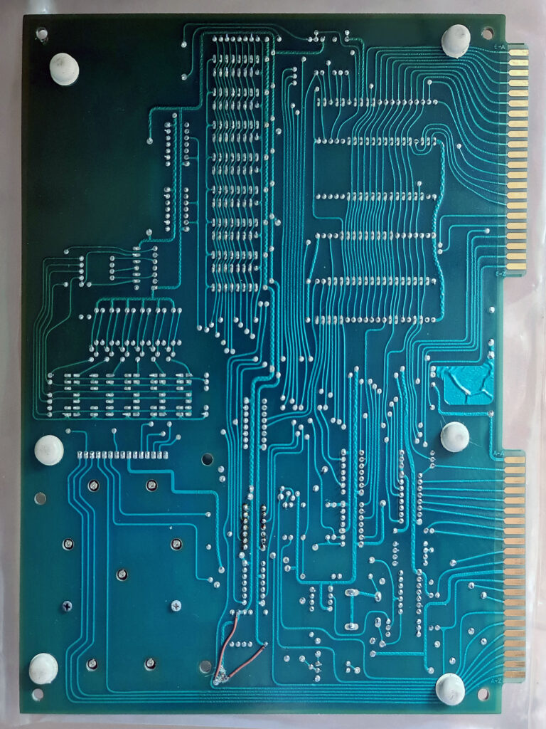
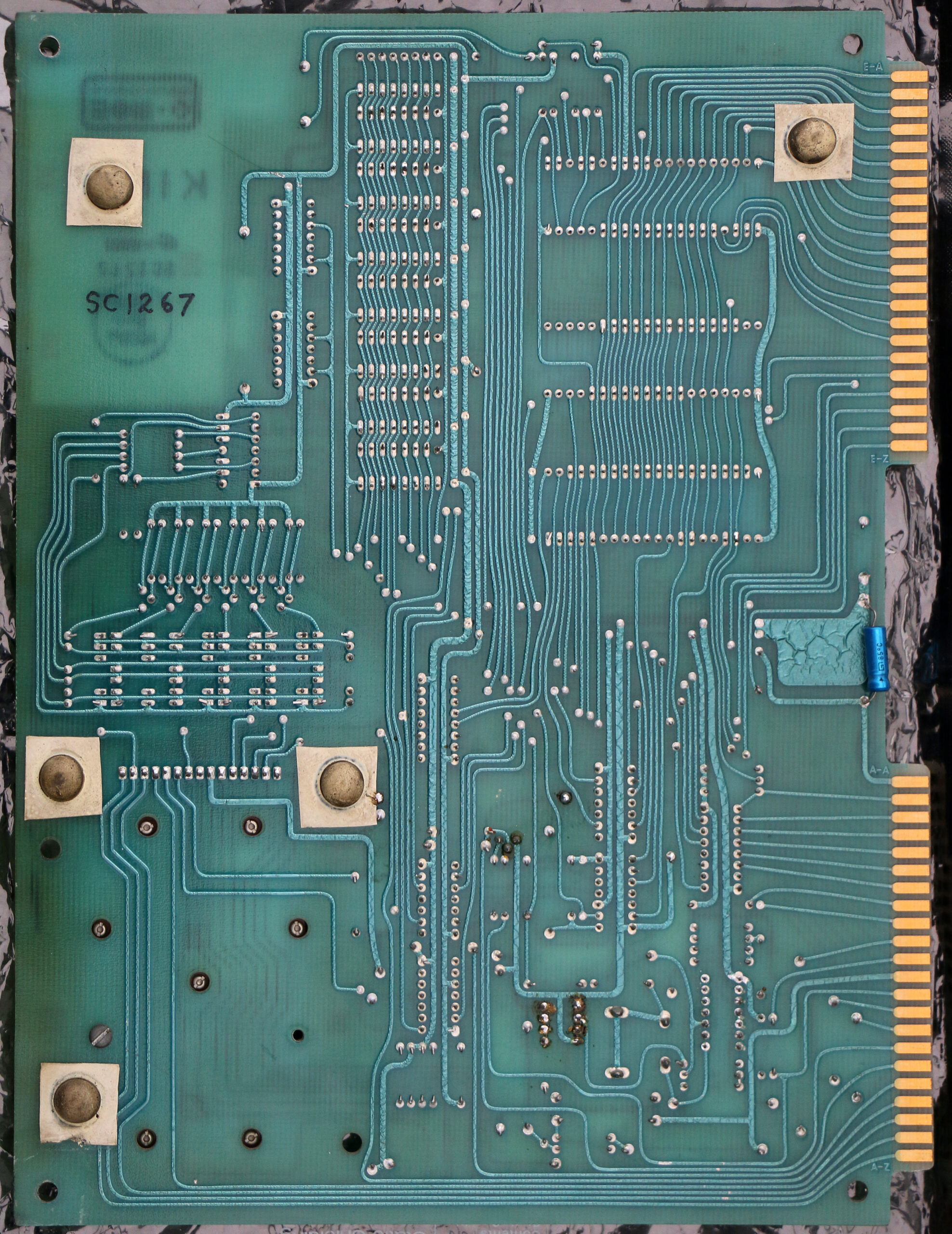
My Micro-KIM shipped with a 65C02, and apparently there is a timing issue which prevents single-step from working with the 65C02. I tried an original NMOS 6502, and single-step worked ok with it, but not with any of my 65C02s. I did some debugging with my scope and determined that there is a small timing difference causing the SST signal to be erroneously asserted (pulled low) for 100-200 ns during EEPROM accesses with the 65C02, which is just enough to cause a problem. The easiest way I could think of to fix this was to delay the SYNC signal briefly with a small RC circuit, which prevents the glitch in the SST signal. I cut a trace on the back side of the board and added a small resistor and capacitor, and single-step is now working correctly with my 65C02’s. It still works with the original 6502, also. Click on the image to see a larger picture.

Photos

Tiny Basic

Microsoft Basic KB9


Videos


https://www.youtube.com/watch?v=R_zD5T_khKs


KIM 6530 to 6532

Replace the 6530-002 and -003 in a KIM-1: a KIM-1 clone.

The base for all ‘modern’ KIM clones, KIM reproductions, MICRO KIM, PAL-1 and more.

Credits to Ruud Baltissen for the idea and details. ‘I’ means Ruud in this page!

RRIOTs are mask programmed for address selection, choices are:

Pin 18 PB6 or CS1
Pin 19 PB5 or CS2
Pin 17 PB7 can have a pullup
ROM selection on RS0, CS1 und CS2 s
RAM on RS0, CS1, CS2, A9, A8, A7 and A6
I/O on RS0, CS1, CS2, A9, A8, A7 and A6
See the various 6530/6532 datasheets for (some) more detail.

The troublemaker: 6530, detailed background information

The KIM-1 has two 6530s on board. For more info about this IC, please read the datasheet. Anybody who is a little bit familiar with the hardware market can tell you that you cannot buy the 6530 anymore. Happily enough there is another IC available which you could call its brother: the 6532. The 6532 has 16 I/O-lines, an internal timer and 128 bytes of RAM on board, but no ROM. The internal ROM of the 6530 can be selected independently from the I/O. So for this project we’ll use an external EPROM as replacement. The pin out of the 6532 is completely different but that should not be a problem.

The next difference is the fact that the 6532 has a separate IRQ and PB7 line. As we will see, the functionality of both lines is the same as with the 6530. To create the same circumstances we only have to connect them together.

The third difference is the availability of PB6 with a 6532. See it as a bonus as I haven’t found any reason how it could jeopardize our project.
The fourth difference is that it is possible to generate an interrupt depending on the behaviour of PA7. But this is an option, which is out of function by default after a reset.

The last and major difference however lays in the way the registers are selected:

function:       RS:  A6:  A5:  A4:  A3:  A2:  A1:  A0:  R/W: 
                                                            
RAM              0    x    x    x    x    x    x    x    x   
                                                            
DRA              1    x    x    x    x    0    0    0    x     A
DDRA             1    x    x    x    x    0    0    1    x     B
DRB              1    x    x    x    x    0    1    0    x     C
DDRB             1    x    x    x    x    0    1    1    x     D
                                                            
PA7, IRQ off,                                               
      neg edge   1    x    x    0    x    1    0    0    0     F
PA7, IRQ off,                                               
      pos edge   1    x    x    0    x    1    0    1    0     G
PA7, IRQ on,                                                
      neg edge   1    x    x    0    x    1    1    0    0     H
PA7, IRQ on,                                                
      pos edge   1    x    x    0    x    1    1    1    0     I
                                                            
read interrupt                                              
       flag      1    x    x    x    x    1    x    1    1     E
                                                            
read timer,                                                 
       IRQ off   1    x    x    x    0    1    x    0    1     J
read timer,                                                 
       IRQ on    1    x    x    x    1    1    x    0    1     K
                                                            
Clock / 1,                                                  
       IRQ off   1    x    x    1    0    1    0    0    0     L
Clock / 8,                                                  
       IRQ off   1    x    x    1    0    1    0    1    0     M
Clock / 64,                                                 
       IRQ off   1    x    x    1    0    1    1    0    0     N
Clock / 1024,                                               
       IRQ off   1    x    x    1    0    1    1    1    0     O
                                                            
Clock / 1,                                                  
       IRQ on    1    x    x    1    1    1    0    0    0     P
Clock / 8,                                                  
       IRQ on    1    x    x    1    1    1    0    1    0     R
Clock / 64,                                                 
       IRQ on    1    x    x    1    1    1    1    0    0     S
Clock / 1024,                                               
       IRQ on    1    x    x    1    1    1    1    1    0     T

In total 5 address lines are used, meaning 32 registers. 
But 11 of the 19 registers have one or more mirrors.
Read:        J E J E       K E K E       J E J E       K E K E 
Write:       F G H I       F G H I       L M N O       P R S T 
R/W:         A B C D       A B C D       A B C D       A B C D       

As we can see, the last 16 registers equal the 16 of the 6530 itself.
So now we have to develop some logic which will do the following:

  • The 6532 is only visible within a range of 128 bytes
  • The first 16 bytes represent register 16 to 31
  • The next 48 bytes are mirrors of the first 16
  • The last 64 bytes appear as RAM

Conclusion:

  • Input A6 won’t be used and can be tied to GND
  • Input A4 is connected to address line A4 of the 6502 via an inverter.
  • A 74LS138/74LS08 construction or equivalent enables the RS- and CS-lines at the right moment.

ROM and RAM

Here we have a luxury problem. We only need 2K of (EP)ROM like the 2716. The problem is that the 2716 is hard to find and more expansive then the 2764 or its bigger brothers. When we use a bigger EPROM we only have to tie the unused address lines to GND. The same problem occurs with the RAM.

If we have to use bigger RAMs or EPROMs anyway, it is quite easy to use other parts of that chip by OR-wiring the CS-line with more Kx-outputs of the main 74145. (Don’t forget the address lines!) In case of the EPROM we also can tie switches to the surplus address lines and have the advantage of a multi-KERNAL system.

Schematics of the new KIM-1

What are the major differences with the original circuit:

  • Replacement of the 6530s by 6532s.
  • Replacement of the 6108 RAM-ICs by one 6264 or equivalent 8K*8 SRAM.
  • Adding an EPROM.
  • Adding a 74LS138 to decode the RAM and I/O of the 6532s.
  • Combining K6 and K7 to one line, dropping the resistor for K6.
  • Adding jumpers to enable combining other K-lines as well.

You may notice that Ruud did not change things which are more or less obvious like replacing the clock circuit by a module or replacing the various 74XX TTL-ICs by their LS or HCT equivalents.

6530’s KIM-1 specification

(Thanks to J Coville)
Back in the day, a designer ordering a custom 6530 would have to specify certain parameters in addition to the ROM contents. During my KIM-1 restoration effort, I found a datasheet for the Synertek version of the part. The datasheet has quite a bit of information describing how to provide the ROM contents. There is also a form for “Additional Pattern Information” (tables to describe the desired chip-select and addressing information). They look like this:

Chip Select Code (Check one square in each block)

CS1
PB6
CS2
PB5
Pull-up on PB7
YES
NO

ROM/RAM/I-O SELECTS (Specify H or L or N (don’t care) in each box.)

RS CS1 CS2 A9 A8 A7 A6
ROM Select N N N N
RAM Select
I/O Select

As best as I can determine, the designers of the KIM-1 filled out the tables for the RRIOTs like so:

6530-002:

CS1 X
PB6
CS2
PB5 X
Pull-up on PB7
YES
NO X
RS CS1 CS2 A9 A8 A7 A6
ROM Select L H N N N N N
RAM Select H L N H H H H
I/O Select H L N H H L H

6530-003:

CS1 X
PB6
CS2
PB5 X
Pull-up on PB7
YES
NO X
RS CS1 CS2 A9 A8 A7 A6
ROM Select L H N N N N N
RAM Select H L N H H H L
I/O Select H L N H H L L

In a KIM-1, K5 is asserted low by addresses 1400-17FF. It is connected to the CS1 lines of both the 6530-002 and 6530-003. A9 and A8 need to be 1 for all I/O and RAM, and A6 and A7 determine which chip and I/O or RAM you get:

0001 0111 00XX XXXX = 1700 – 173F = 6530-003 I/O
0001 0111 01XX XXXX = 1740 – 177F = 6530-002 I/O
0001 0111 10XX XXXX = 1780 – 17BF = 6530-003 RAM
0001 0111 11XX XXXX = 17C0 – 17FF = 6530-002 RAM

The RS lines are connected to different select lines, K6 for 6530-003 and K7 for 6530-002, this gives:
0001 10XX XXXX XXXX = 1800 – 1BFF = 6530-003 ROM (1k)
0001 11XX XXXX XXXX = 1C00 – 1FFF = 6530-002 ROM (1k)

All these values agree with the KIM-1 memory map documentation.

K0 $0000 – $03FF 1024 bytes of RAM (8*6102)
K1 $0400 – $07FF free
K2 $0800 – $0BFF free
K3 $0C00 – $0FFF free
K4 $1000 – $13FF free
K5 $1400 – $16FF free
$1700 – $173F I/O, timer of 6530-003
$1740 – $177F I/O, timer of 6530-002
$1780 – $17BF 64 bytes RAM of 6530-003
$17C0 – $17FF 64 bytes RAM of 6530-002
K6 $1800 – $1BFF 1024 bytes ROM of 6530-003
K7 $1C00 – $1FFF 1024 bytes ROM of 6530-002

K0..K7 = output lines from 74145

post

KIM 6530 replacement

Have a KIM-1 with faulty 6530? Look here for replacement with 6532 and some.

post

KIM-1 6530 Replacements

On this page two KIM-1 replacements are presented.

Based on the same design principles of 6530 with a 6532 + ROM and glue logic, as also used in .

Both solutions are made up of a PCB with 6532 + ROM and glue logic. The defective 6530(s) need to be replaced with an IC socket, the replacement board is fitted in the IC socket on top of the KIM-1.
Which one you choose depends on the state of the KIM-1. If only one of the 6530s is damaged, the Corsham solution is the right one. If both 6530s need replacement the Eduardo Casino design is the appropiate solution.

post

TIM 1 System by Joseph Watson

In the Facebook group ‘6502 programming’ Joseph Waton published a story about his TIM 1 system and photos.

13902788_1297285456956011_4038706379477634999_n

post

VAE T4 system

The dutch company Visser Assembling Electronics, Alkmaar, working for and in cooperation with the dutch carpet-factory Forbo Krommenie, developed a system based upon the KIM-1.
The T4 system consist of a large portfiolio of RAM, ROM, EPROM, input (Analog and Digital) and Output boards. Also a videoram card was developed.

Scanned documentation and all photos of the system

kim

kim

kim

kim

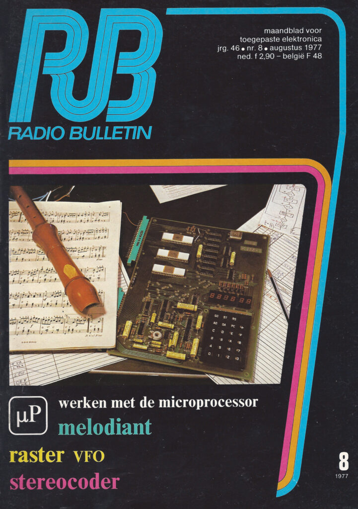
Radio Bulletin

The dutch magazine Radio Bulletin (RB, RB Electronics) has a long history, going way back to the early years of electronics. The name was derived from what electronics meant for amateurs in these days: building radios yourself.
It was published by Uitgeverij de Muiderkring, a publishing company in the Amroh group of companies.

The magazine was published in large volumes in the years 1970-1985, due to the popularity of do-it-yourself electronics and audio. Also the beginning of the microprocessor revolution was adequately covered and the great years of the hobbycomputers 1980-1990 were contributing to the success. Besides the magazine Uitgeverij de Muiderkring published many books on electronics. After 1990 the success faded and the magazine left the mass market and stopped in 2003. The publishing company Uitgeverij de Muiderkring, together with Amroh, went bankrupt in 2002 (I lived closely to the last location and saw the empty offices when passing by).

In 1977 Dick de Boer joined the staff of RB and introduced the readers to microprocessors and in particular the 6502 and the KIM-1. Also the KIM Gebruikers Club and the HCC were founded that year and RB started to write articles about all this exciting new developments!
I was then already a freelance writer about electronics but Dick made me study the microcomputer such as the KIM-1 and made me join the KIM
Gebruikers Club and the HCC (member 760 member). Dick de Boer, his successor Paul de Beer and me (Hans Otten) and others wrote many articles about the KIM-1 and related 6502 based systems for Radio Bulletin. Especially Dick wrote good introduction articles and developed sophisticated hardware and software like a graphical display. After leaving the magazine he became a software engineer and helped me also to my first job as software engineer in 1980. Me and Paul de Beer concentrated more on expanding 6502 systems like the KIM-1 with memory (RAM, ROM) and I/O cards like PIA, VIA and ACIA and mass-storage such as the Mini Digital Cassette Recorder. The bus of this expansion system was the so called BEM-bus.

I did translate a book Computer Interfaces by Owen Bishop for de Muiderkring to dutch. A scanned version is presented here.

All these articles are downloadable here, as they describe my publishing history and my KIM-1 system, designs by us of which the prints sold quite well. As you can see in the long list of articles the KIM and the 6502 played a major role in the microprocessor revolution starting in 1977 and lasting until 1987 for me.

What you see about Amroh, Uitgeverij de Muiderkring and Radio Bulletin is:

Selection of my and others articles 1977 – 1987 in Radio Bulletin
the RB Specials
the Cosmicos 1802 CPU based system by H.B. Stuurman, book and articles
some bits about the long history of Radio Bulletin
Elektronica ABC, the diy magazine

See also:

– Dr Blan articles on Step-by-Step radios
– Step by Step radio by Amroh

post

KIM-1

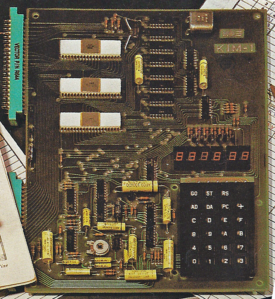
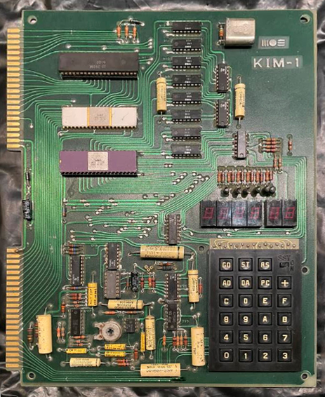
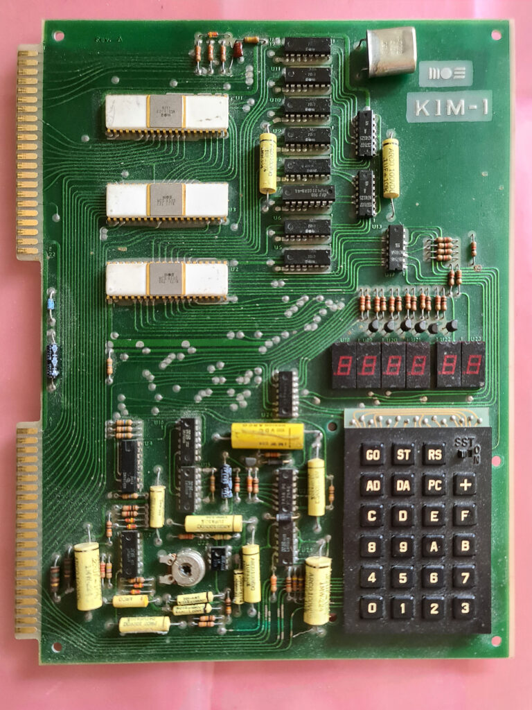
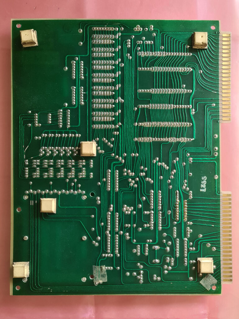
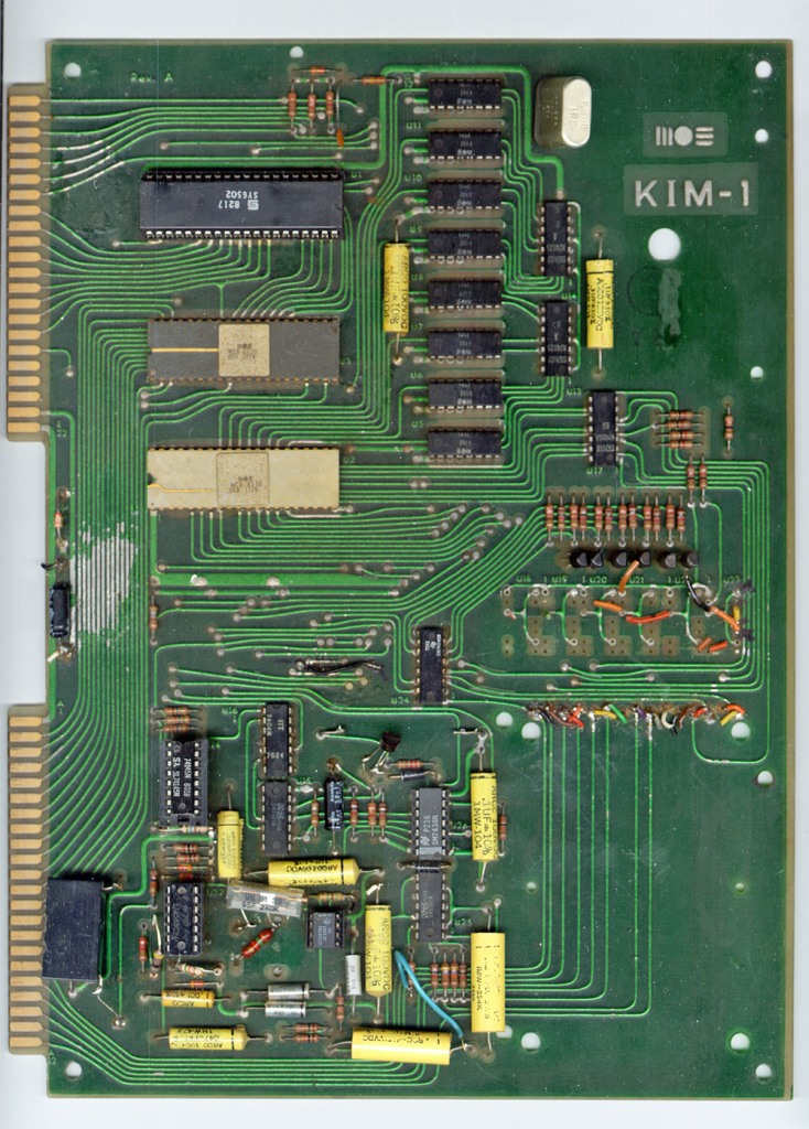
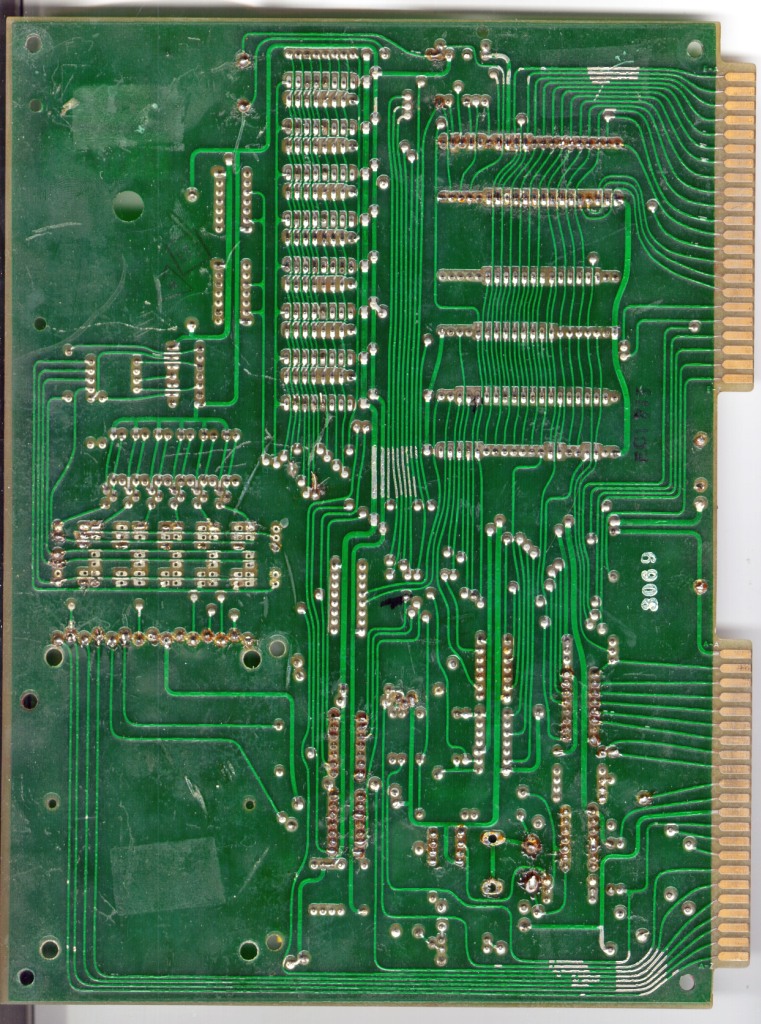
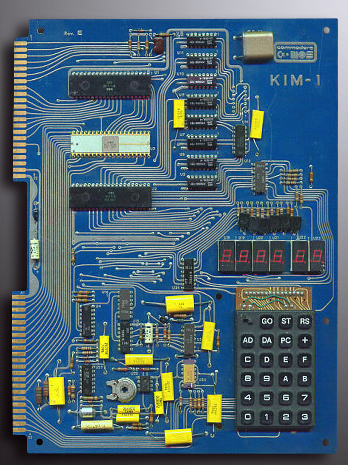
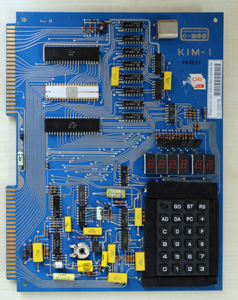
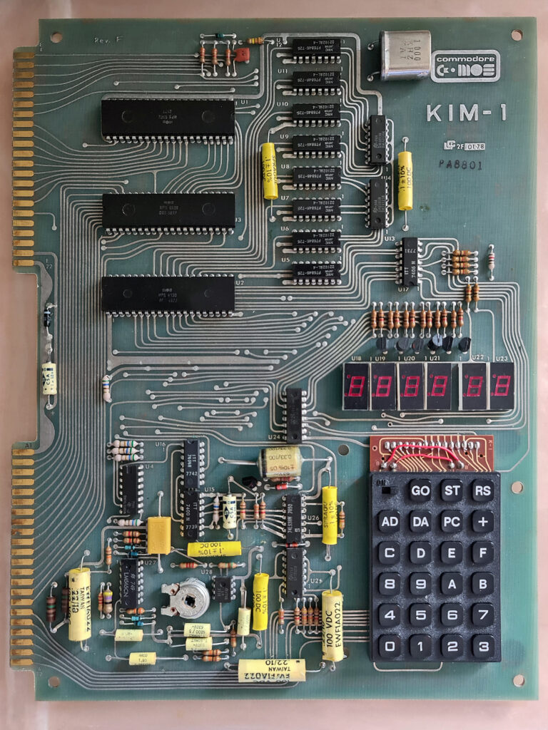
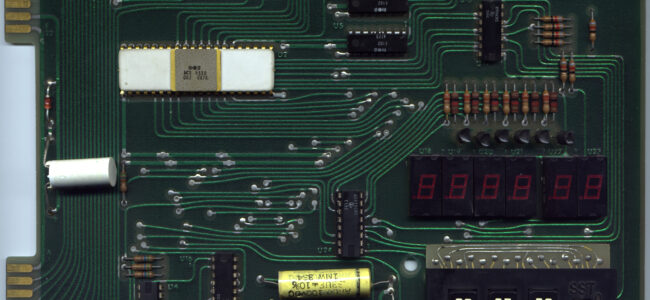
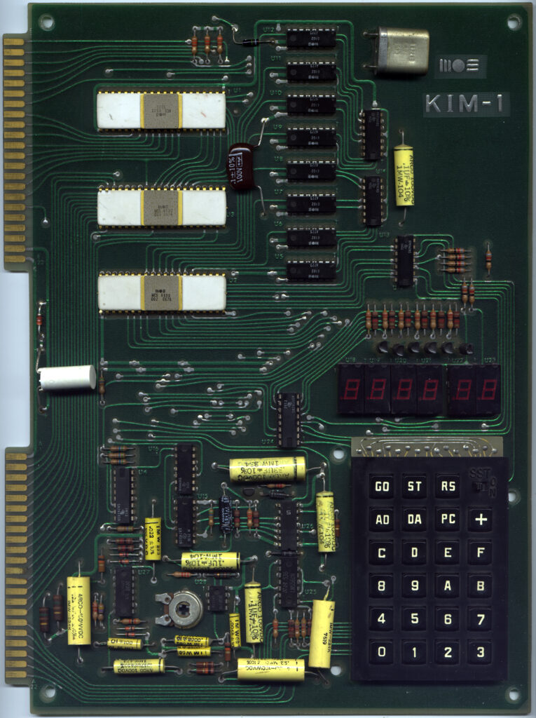
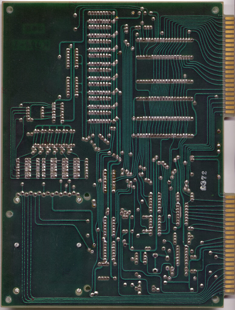
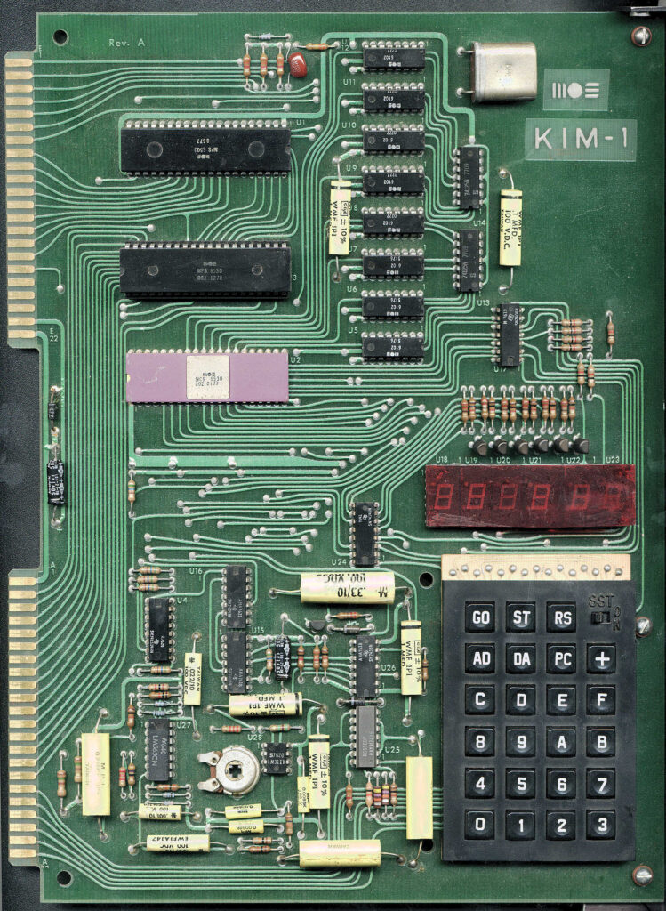
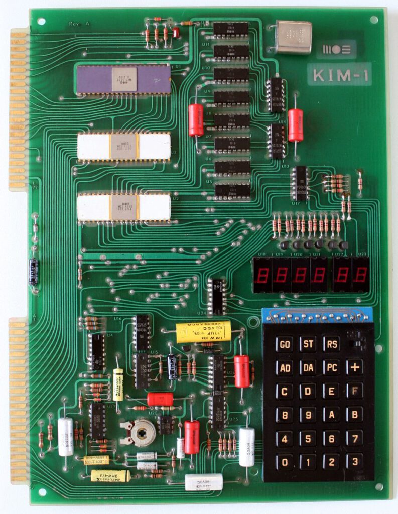
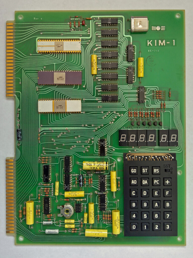
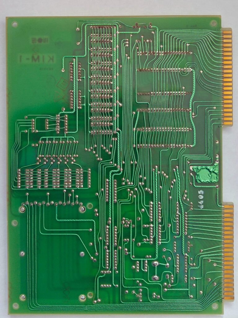
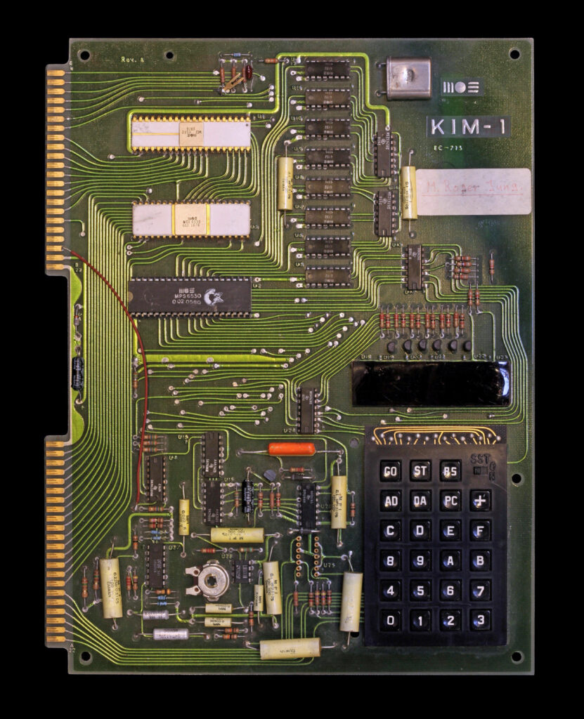
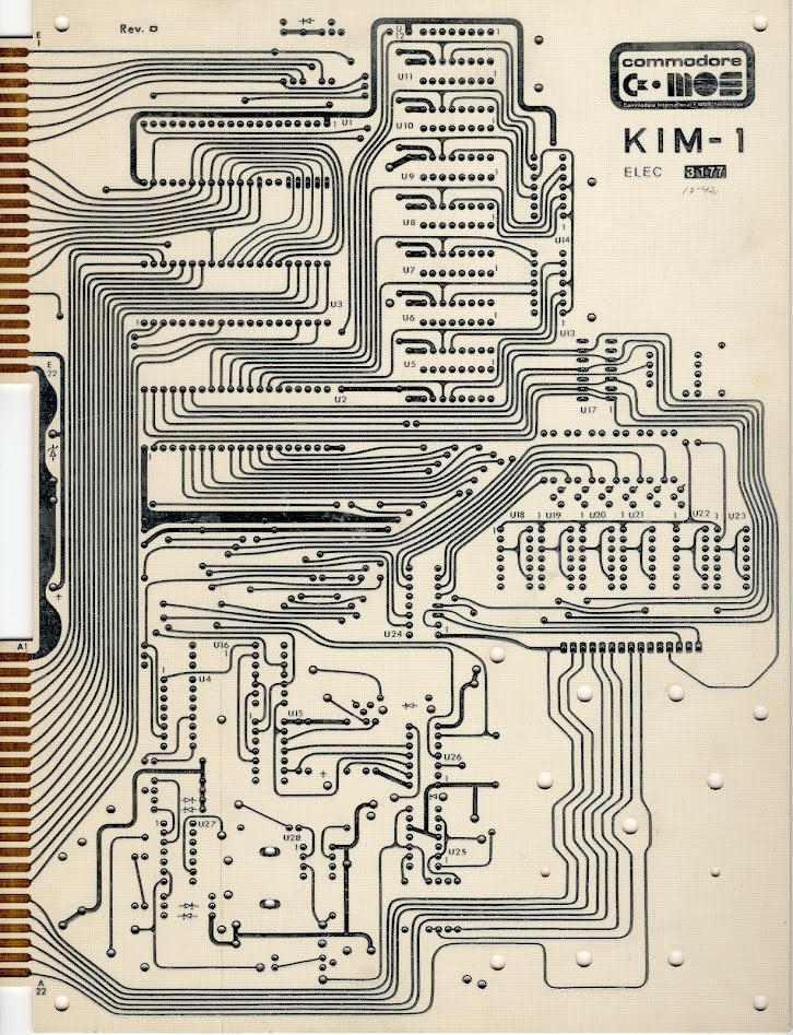
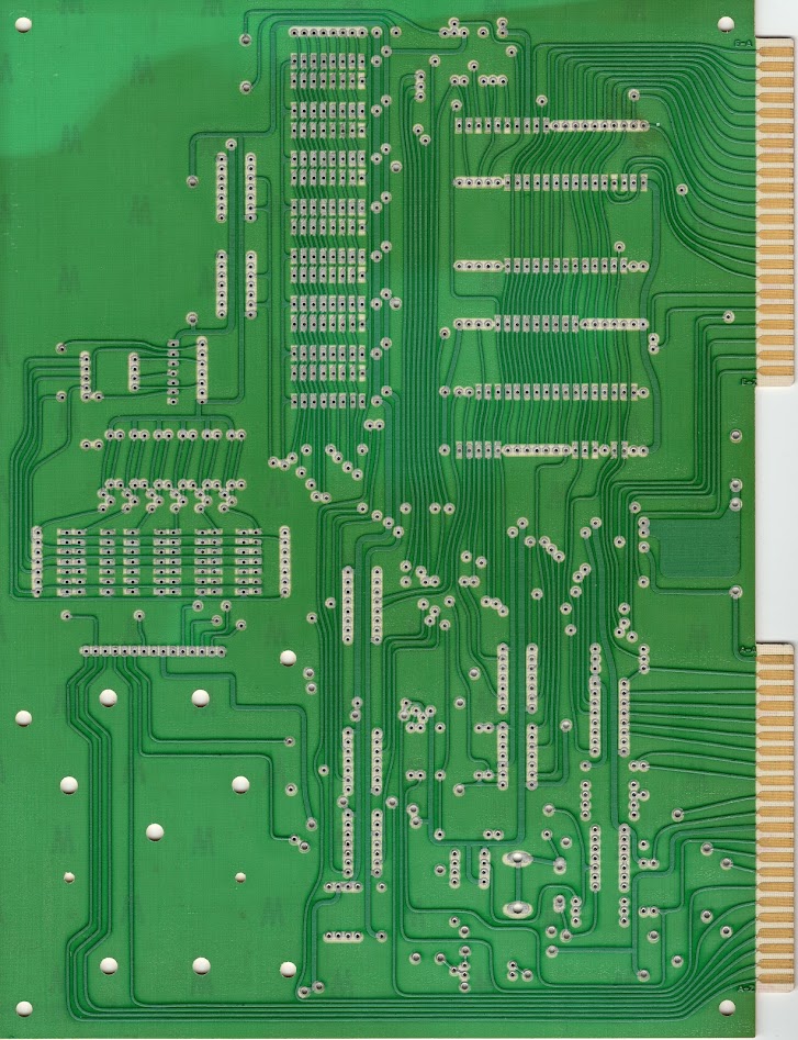
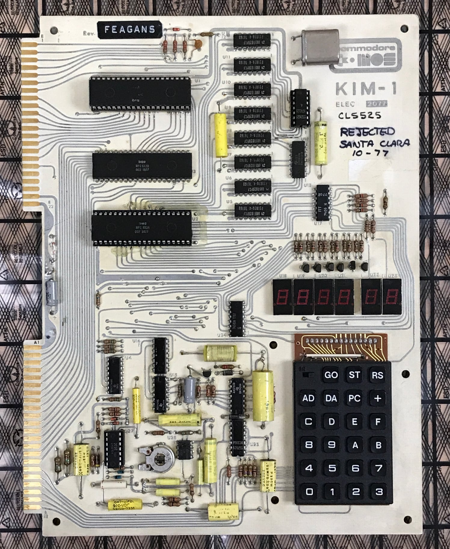
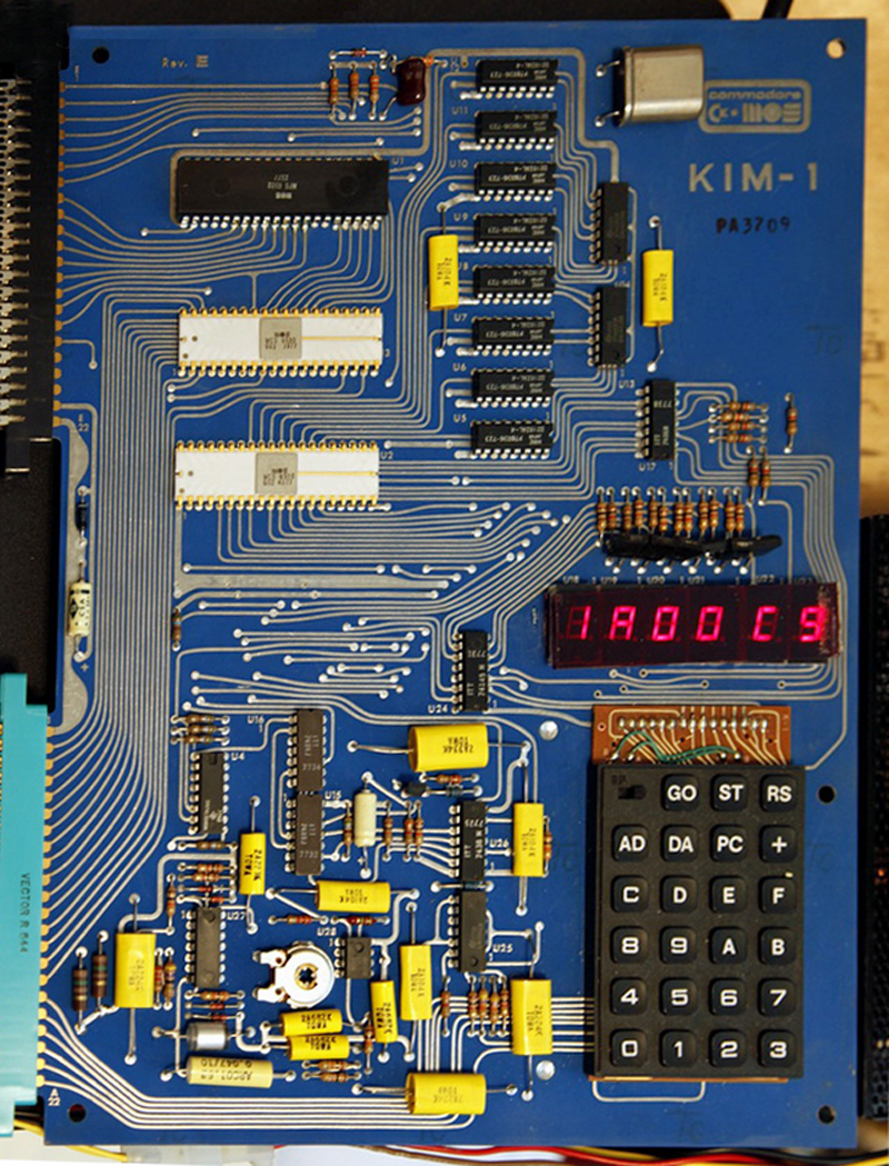
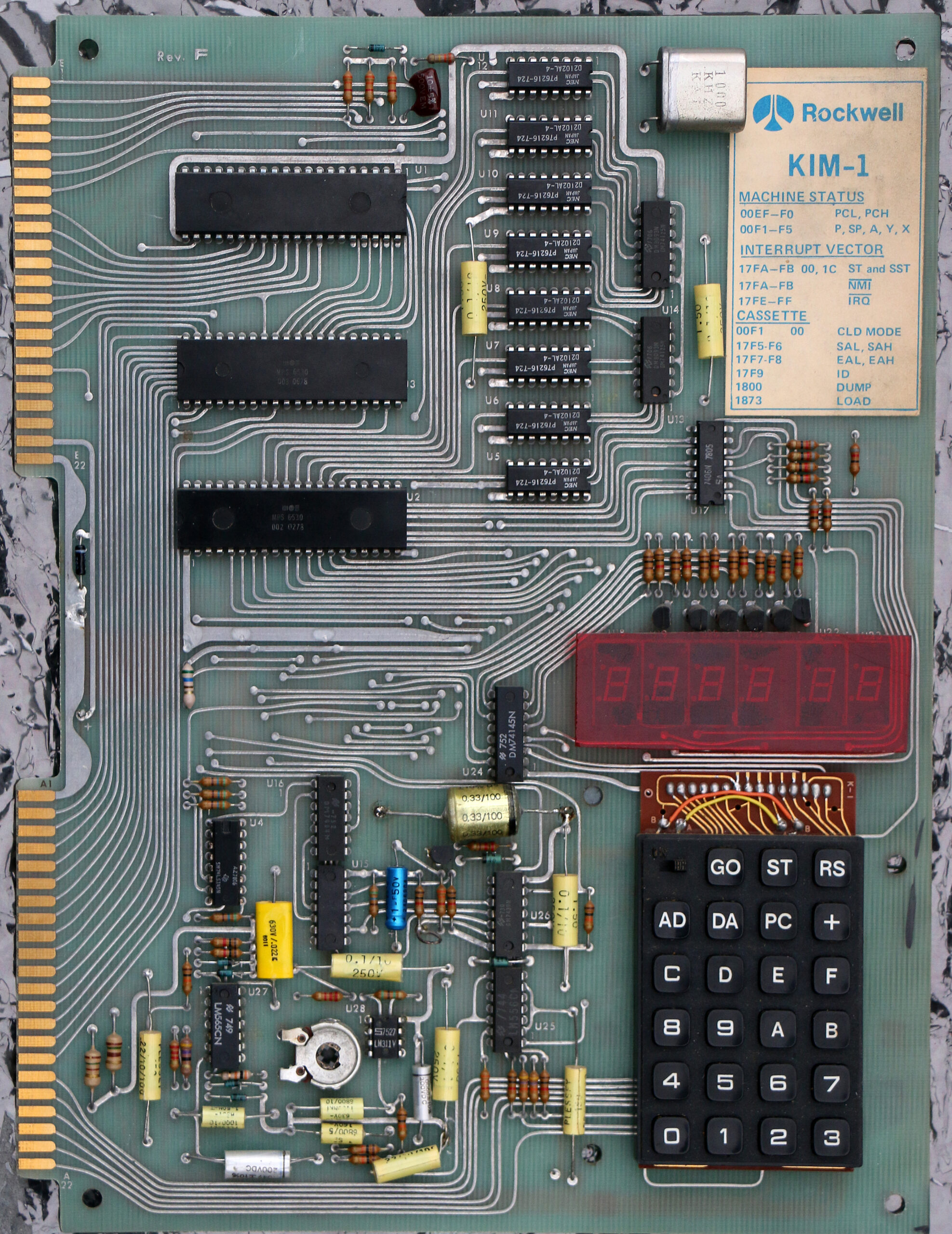
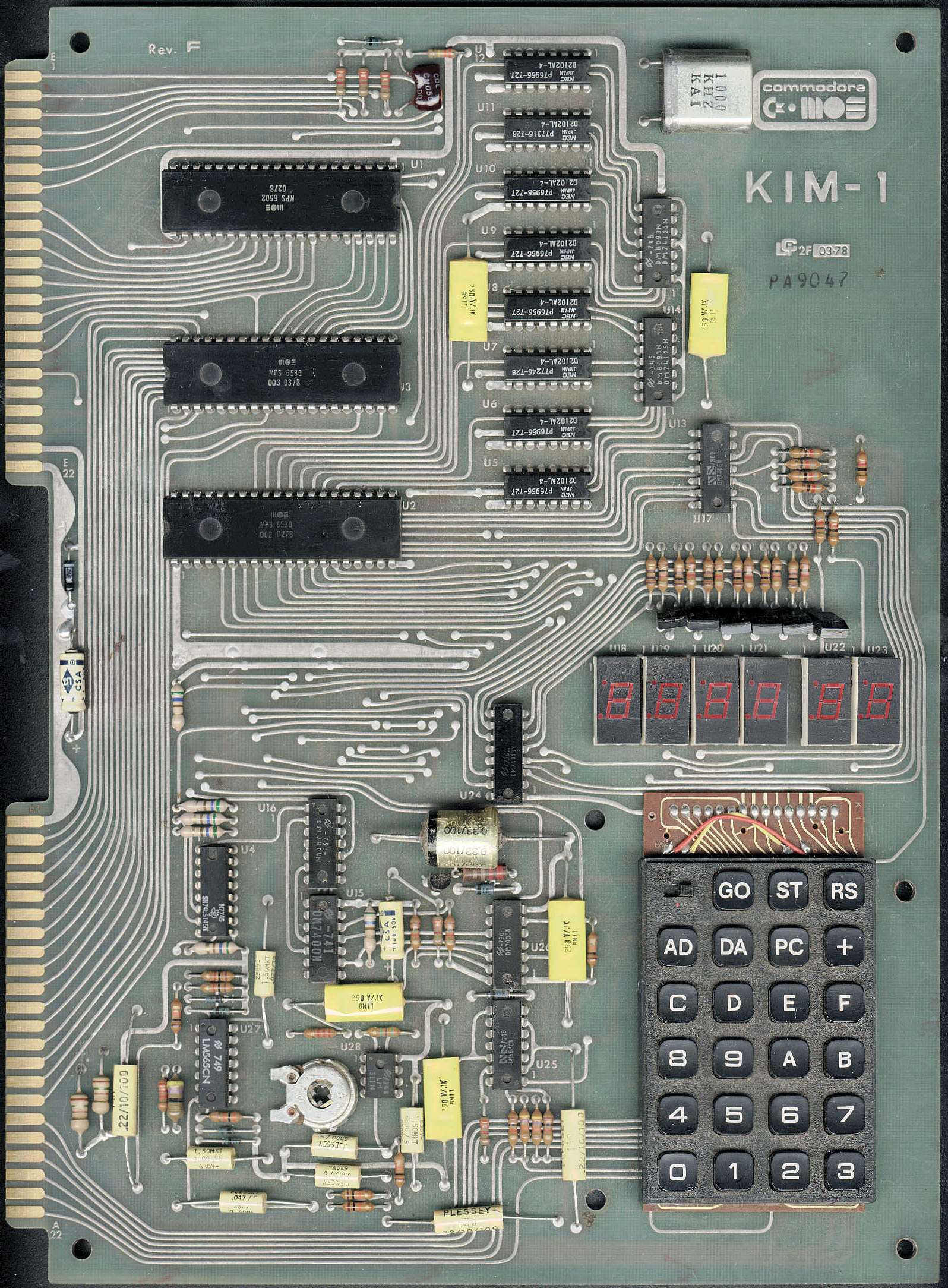
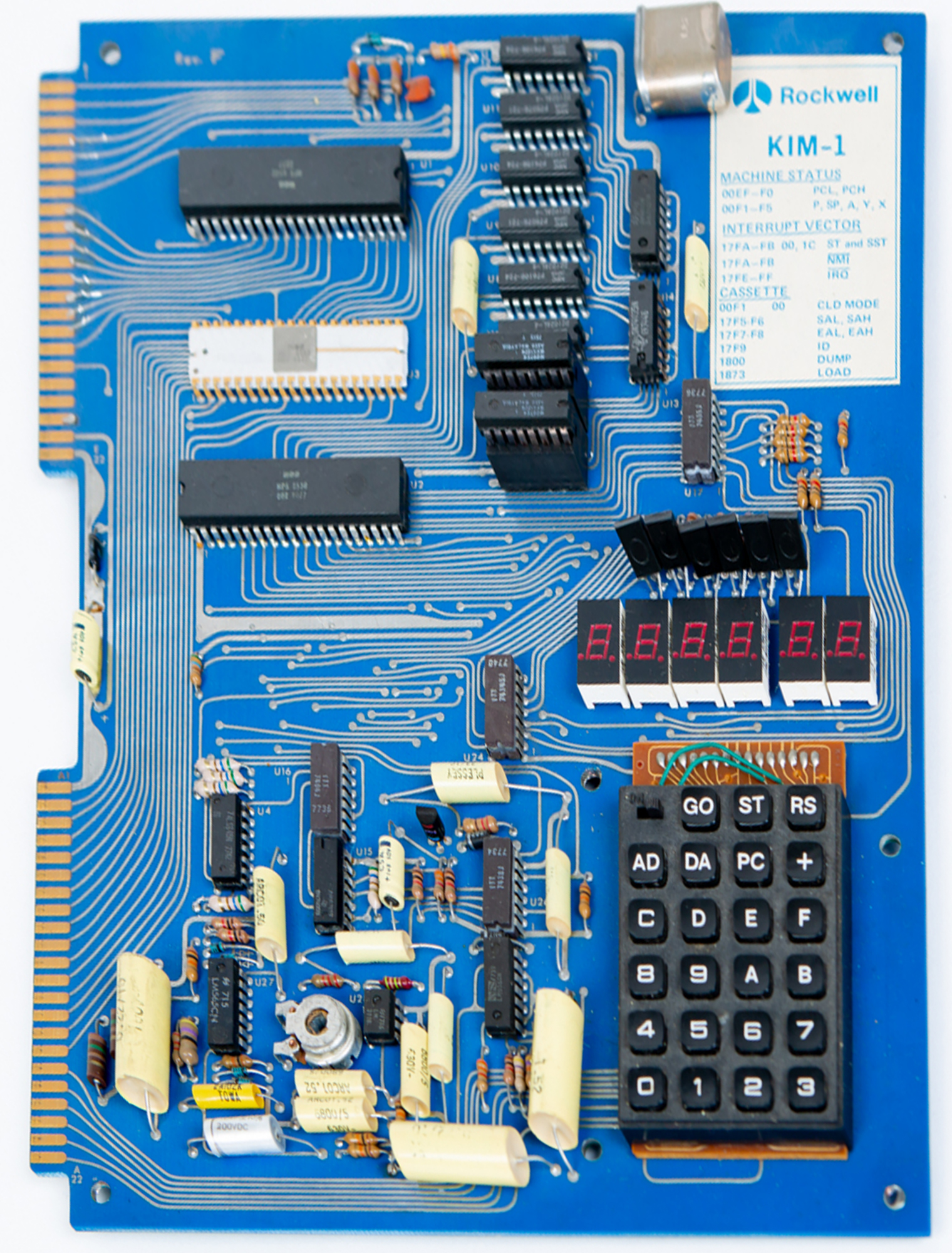
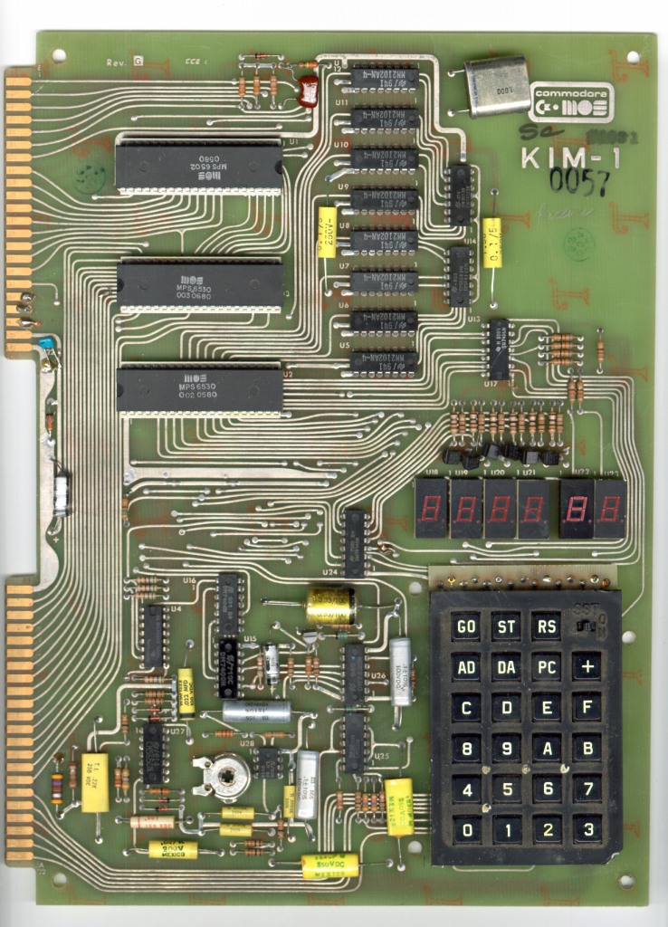
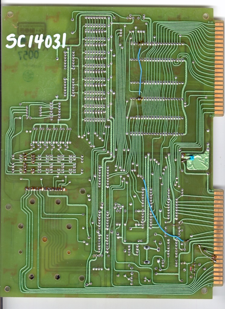
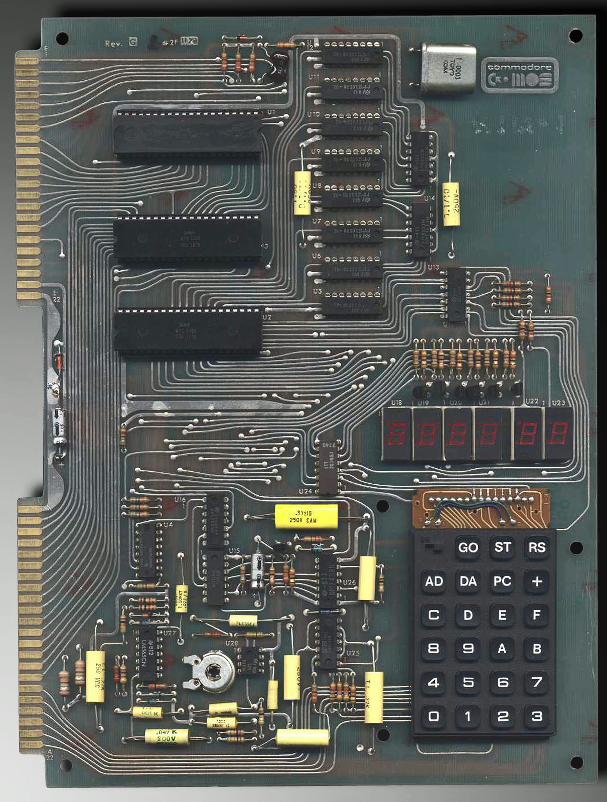
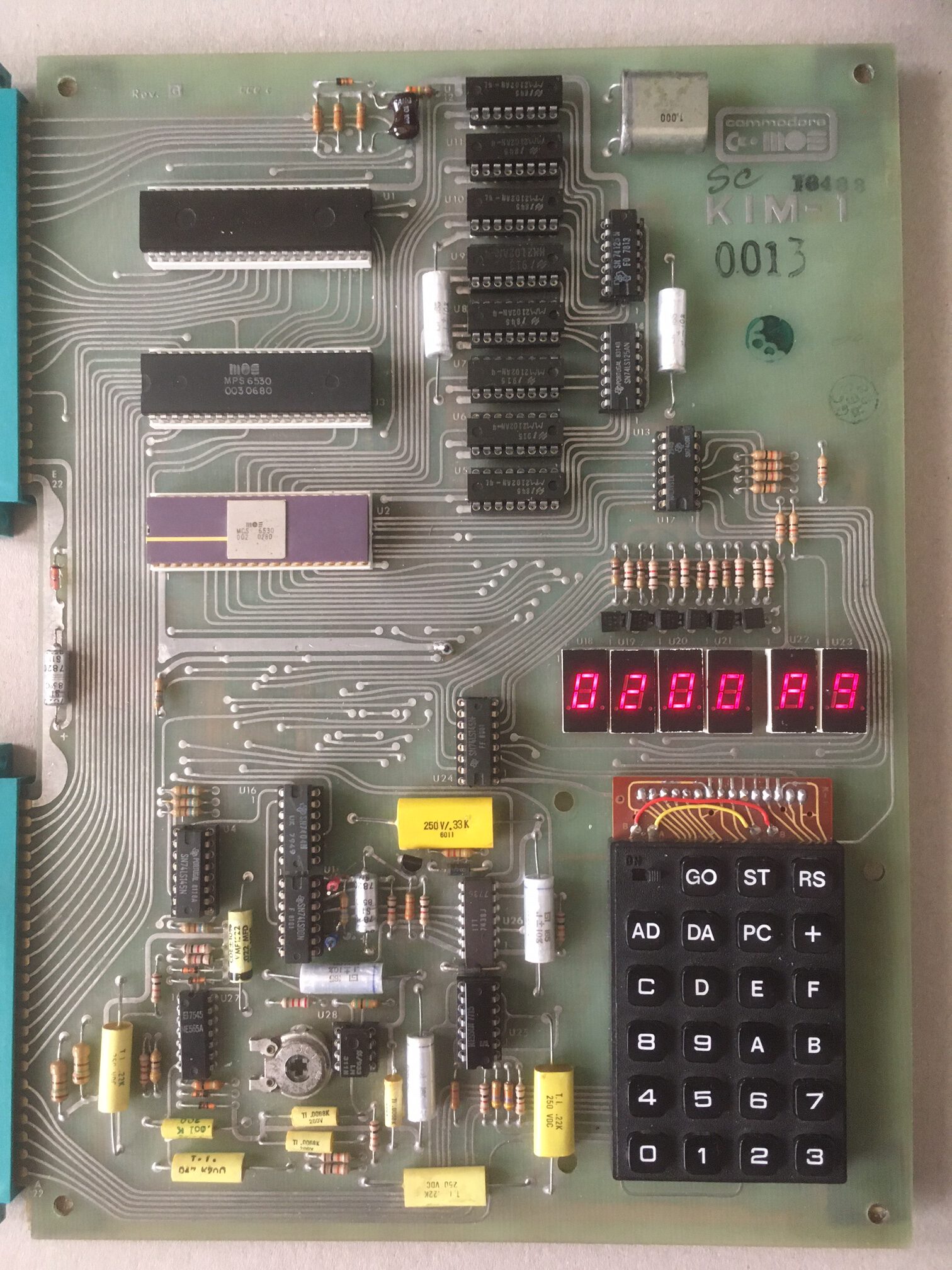
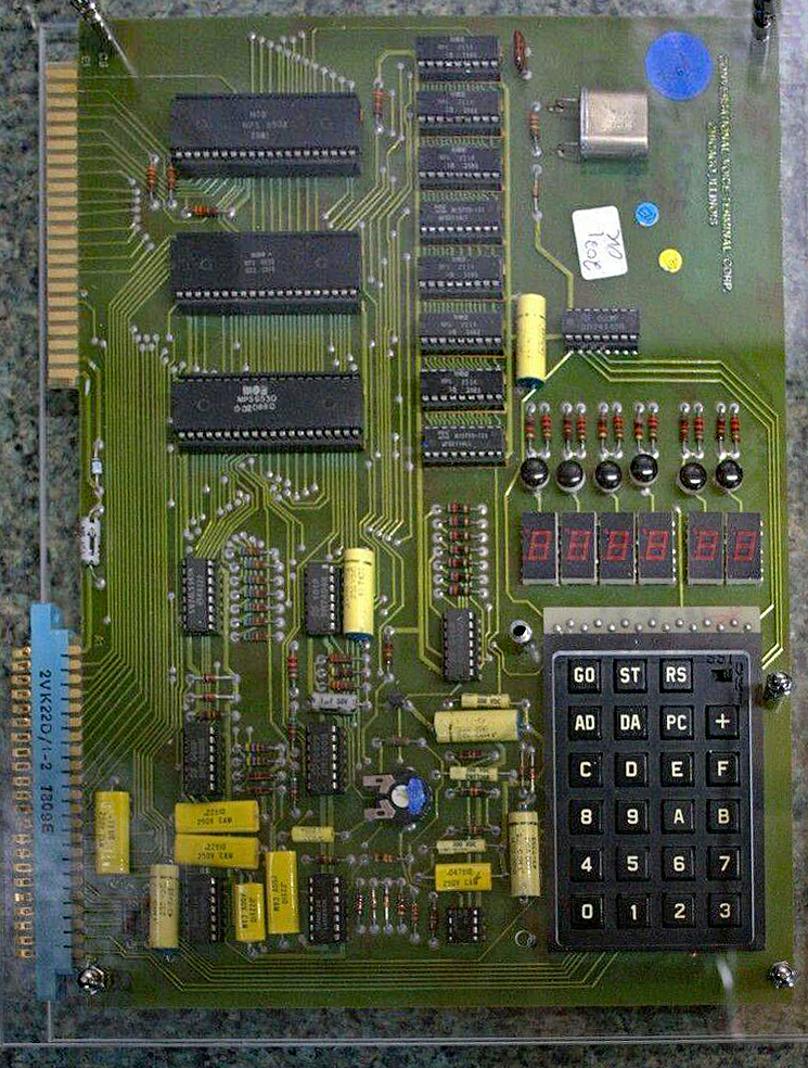
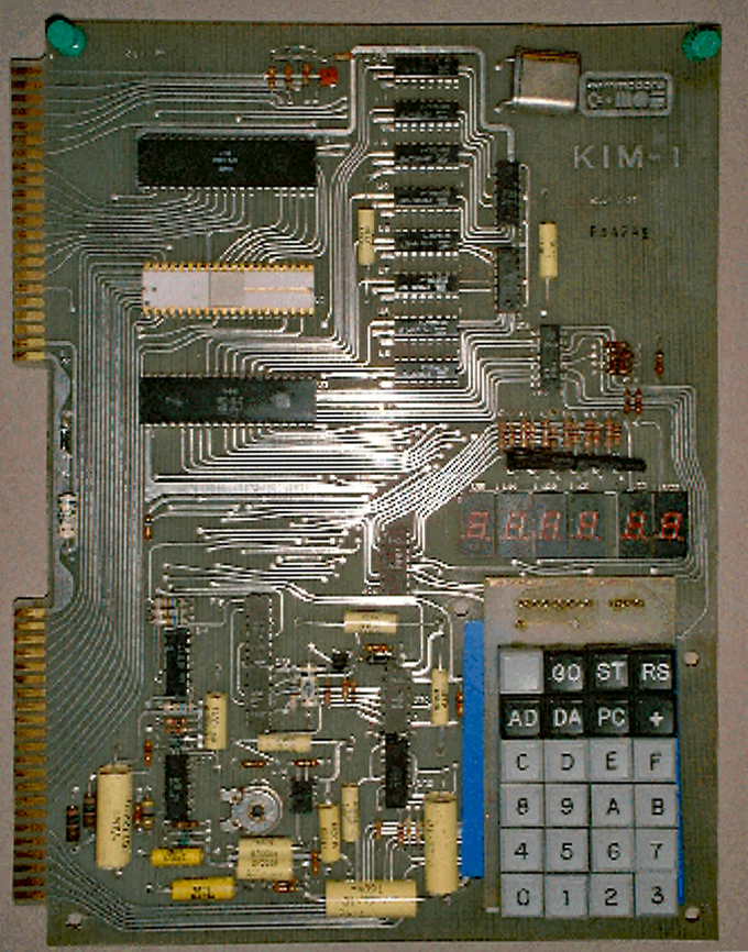
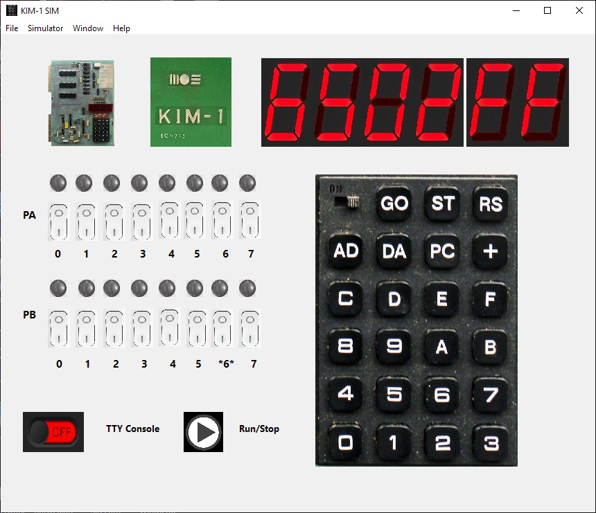
Developed by Mos Technology. later acquired by Commodore, to show the possibilities of the 6502 microprocessor but quickly discovered as the first mass-produced personal computer. Easy to extend, lots of detailed documentation. With assembler/editors, first Microsoft Basic on cassette and even a Pascal compiler, it could do a lot. The first have an original Mos Technology logo, later versions have the Commodore logo on the board, small technical differences other than more recent 6502 IC’s without the infamous ROR bug.
IMG_9755
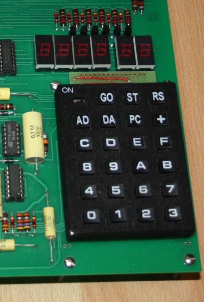
This prehistoric computer has no “real” keyboard and no video output, program are entered by the small hexadecimal keyboard (located in the lower right part of the picture) and results are displayed on the small LED “screen” (it can display only 6 digits). It has a simple monitor that allows one to examine & modify memory, load and save paper tape, load and save cassette tape, run and debug programs through a ‘single step’ mode. The monitor works with the built in keypad and LEDs, or a terminal like the Teletype ASR33. This 20 mA current loop is easy to adapt to RS232C and so any videoterminal can be used.

Information on the KIM-1, also reachable from the menu on the right:

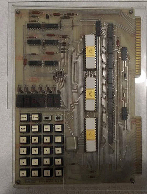
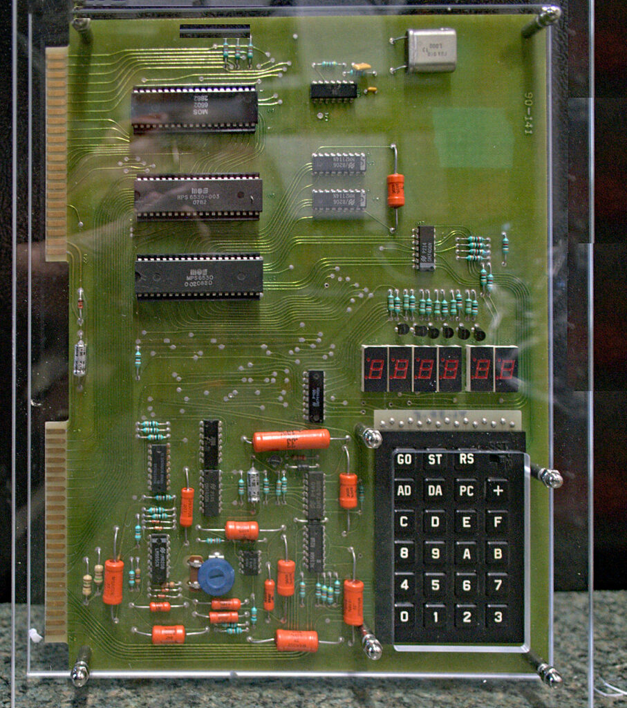
Prototype KIM-1

On team6502  I found a photo of a prototype KIM-1 at MOS Technology, Terry Holdt has this in his office.
The layout is different from the final product, everything seems to be present on this prototype.

KIM in test frame at a MOS Technology facility (John Feagans)