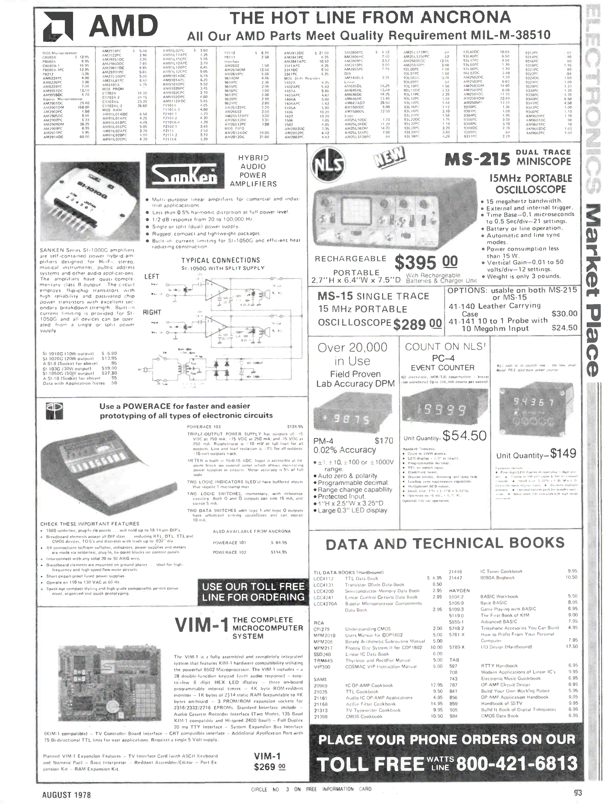
Diese erste Deutsche Fachzeitschrift für die kleinen Computer wurde von Roland Löhr, Ahrensburg, in den Jahren 1978-1985 herausgegeben.
65xx Micro Mag 1
65xx Micro Mag 2
65xx Micro Mag 3
65xx Micro Mag 4
65xx Micro Mag 5
65xx Micro Mag 6
65xx Micro Mag 7
65xx Micro Mag 8
65xx Micro Mag 9
65xx Micro Mag 10
65xx Micro Mag 11
65xx Micro Mag 12
65xx Micro Mag 13
65xx Micro Mag 14
65xx Micro Mag 15
65xx Micro Mag 16
65xx Micro Mag 17
65xx Micro Mag 18
65xx Micro Mag 19
65xx Micro Mag 20
65xx Micro Mag 21
65xx Micro Mag 22
65xx Micro Mag 23
65xx Micro Mag 24
65xx Micro Mag 25
65xx Micro Mag 26
65xx Micro Mag 27
65xx Micro Mag 28
65xx Micro Mag 29
65xx Micro Mag 30
65xx Micro Mag 31
65xx Micro Mag 32
65xx MicroMag Inhalt 1-32 (also listed here after)
65xx Micro Mag 33
65xx Micro Mag 34
65xx Micro Mag 35
65xx Micro Mag 36
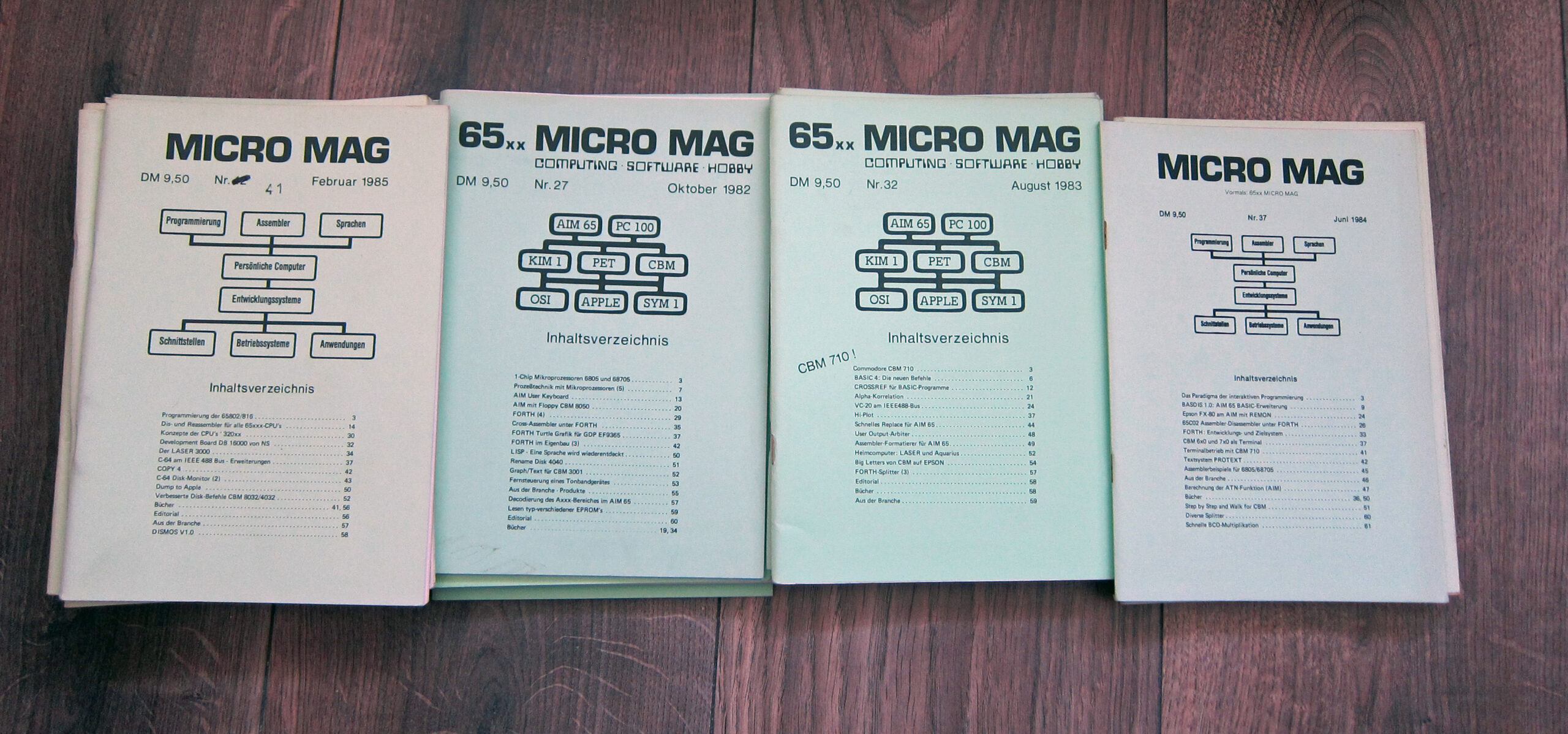
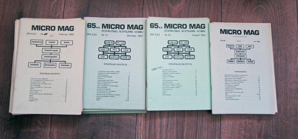
The name changed after Issue 36, the 65XX was dropped to represent the wider nature of the magazine.
Micro Mag 37
Micro Mag 38
Micro Mag 39
Micro Mag 40
Micro Mag 41
Micro Mag 42
Micro Mag 43
Micro Mag 44
Micro Mag 45
Micro Mag 46
Micro Mag 47
Micro Mag 48
Micro Mag 49
Contents of Nr. 1 1978 to Nr 32 1983
Numbers are either the Issue number (pointing to one of the PDF’s above) or a B1 Buch 1: Issue 1-6, B2 Buch 2: Issue7-13
Allgemeine Themen
-Wie soll man Arbeitsspeicher bereitstellen? B1-77
-Adreßkonstante vs. Verschieblichkeit B1-78
-Formate und Kompatibilität bei der Magnetbandaufzeichnung B1-82
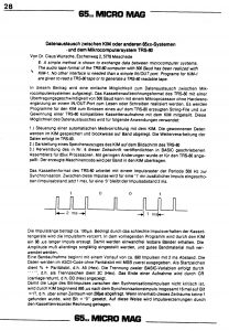
-Datenaustausch zwischen KIM-1 und TRS 80 7-28*
-Erzeugung quasistatischen Rauschens durch Zufallszahlenfolgen 7-43*
-Zufallszahlengenerator 8-35*
-Magnetbandbetrieb 9-32*
-Umbau eines Cassettenrecorders 9-35*
-Anschluß von numerischer Anzeige und Tastatur (1) 11-31*
-Interruptgetriebene Cassettenein- und Ausgabe 12-23*
-Anschluß von numerischer Anzeige und Tastatur (2) 12-32*
-Wie liest man ein Programm-Listing? 13- 8*
-Anschluß von numerischer Anzeige und Tastatur (3) 13-20*
-Basic DATA-Generator 13-33*
-Interruptgetriebene Cassettenein- und Ausgabe (2) 13-43*
-Rechtsbündige Zahlenausgabe 14-41
-Datenaustausch zwischen zwei Mikroprozessorsystemen (1) 15-53
-Steuerung – elegant per Assembler 16-16
-Datenaustausch zwischen zwei Mikroprozessorsystemen (2) 16-55
-Datenaustausch zwischen zwei Mikroprozessorsystemen (3) 17-27
-Rechnerkopplung mit Interrupt 17-31
-Die (Un-)Zuverlässigkeit von Kassettenspeichern 17-32
-Hannover-Messe 1981 18-47
-Einkommensteuerberechnung 1980 19-71
-PRINT-Formatierung 19-35
-Prozeßtechnik mit Mikro-Computern (1) 20- 3
-Einkommensteuerberechnung 1981 21-46
-Feedback 21-47
-Prozeßtechnik mit Mikro-Computern (2)
-BASIC-Formatierungen 22-57
-Prozeßtechnik mit Mikro-Computern (4) 23-23
-Lösung der kubischen Gleichung 23-26
-Formatierte Zahlenausgabe 23-27
-SHAKE (Permutationen) 23-30
-RAM-EPROM-Karte 4 kB g 4 kB 23-36
-BASIC mit Struktur 23-39
-Geisterzeilen im Microsoft-BASIC 23-42
-Low Cost Typenraddrucker 24-41
-Prozeßtechnik mit Mikro-Computern (3) 24-50
-Hinweise für Autoren 24-57
-Prozeßtechnik mit Mikro-Computern (4a) 25-54
-SHAKER 25-60
-Low Cost Typenraddrucker (2) 26-32
-Timesharing 26-44
-Prozeßtechnik mit Mikro-Computern (5) 27- 7
-LISP – eine Sprache wird wiederentdeckt 27-50
-Lesen typ-verschiedener EPROMs 27-59
-Code-Wandler 28-20
-Prozeßtechnik mit Mikro-Computern (6) 28-28
-Parser und Entscheider 29- 3
-Symbolisches Differenzieren (BASIC) 29-33
-Symbolisches Differenzieren (LISP) 29-41
-Multi-TASK bei Mikrocomputern 29-50
-Einkommensteuerberechnung 1982 29-56
-MOVE und RELOCATE 30-31
-Spätlese 30-61
-32 kB CMOS-RAM 31-46
-Supertape – Kassettenaufzeichnung mit 600 Byte/Sek. 32-52
-Hi-Plot 32-37
6502
-Ein Leitfaden ein die Programmierung B1- 1
-ASP – Advanced Subroutine Package B1-35
-Makros für 65xx B1-67
-SWEET 16 B1-20
-Neue Intelligente Peripheriebausteine B1-81
-Die VIA 6521 7- 3*
-ASP – Advanced Subroutine Package (6) 9-22*
-Align für ALPHA-SORT 9-28*
-Ein Leitfaden für die Programmierung (4) 9-41*
-Interrupt-Demonstrationsprogramm für die VIA 6522 10-24*
-Ein Leitfaden für die Programmierung (5) 10-30*
-Geschachtelte Interrupts 12-28*
-Pseudo 16-Bit CPU 18-18
-APPLE II emuliert AIM 65 20-31
-VNITEX – Universale Textausgabe 21-30
-Binär-BCD-Wandlung 22-2)
-Druckerausgabe auf parallele Schnittstelle 22-30
-6502 Multiplikation, Division 22-31
6805/68705
-1-Chip Mikroprozessor 6805 und 68705 27- 3
6809
-Ein fortschrittlicher Verwandter: MC 6809 15- 3
-MC 6809: Register, Signale, Befehle 18- 3
-MC 6809: Befehle (1) 19-20
-MC 6809: Befehle (2) 20-50
-Adressierungsarten des 6809 22-42
-BASIC-Disassembler für 6809 24-10
68000
-Wichtige Merkmale des MC 68000 30- 3
-Interfacebaustein PI/T 68230 30- 7
CBM und PET
-PET 6502-Assembler B1-212
-Der PET-Assembler 7-37*
-PET Video-Driver 7-38*
-Primfaktoren-Zerlegung 8- 3*
-Video-Edit (PET) 8-11*
-PET-Petits 8-14*
-TRACE (PET) 9- 3*
-VIEW (PET) 9- 5*
-Text-Editor (PET) 9- 6*
-PETROL (Bildschirm rollen) 9- 9*
-RESTORE Line Number (PET) 9-13*
-Datenverbund zwischen AIM 65 und PET 2001 9-14*
-CBM-VIEW, neue Befehle 10-20*
-Berechnetes GOTO für den CBM 10-21*
-Tape Catalog (CBM) 10-41*
-Disk Utility Program (CBM) 11- 6*
-6502 Direct Assembler (PET) 11-12*
-Schaufel Relocate, (PET) 11-16*
-VARLIST (Variablenausdruck, PET) 11-17*
-CBM schießt sich eigene EPROMs 11-24*
-ROM-Vergleichsliste CBM-PET 11-28*
-BASIC Keywords to Shifted Keys 12- 3*
-CBM UNIPLOTT 12-48*
-Der CBM-Assembler 13-78*
-Binäres Speichern von Zahlen 13-27*
-BLANK-DELETER 13-29*
-Automatische Zeilennumerierung PET/CBM 14-33
-Das Auffinden einer BASIC-Variablen 14-35
-Dekadischer Logarithmus per USER 14-36
-Garbage Collection Routine im CBM 14-38
-Sichern und Laden dimensionierter Variablen 14-42
-Programmveränderung (CBM) 15-15
-Zeitanzeige auf PET und CBM 15-21
-INPUT-Routine (PET) 15-57
-Ein Sortierprogramm ein CBM 3001 16- 3
-Tastentest ein CBM 3032 16-53
-PASCAL ein CBM 17- 3
-Kaufmännisches Rechnen auf dem CBM 17- 9
-Grafik-Zugriff beim CBM-Busy 17-14
-1/4-0rafik für CBM 3001 17-15
-CBM 3032: Benutzung arithmetischer Interpreterroutinen 17-44
-ON ERROR GO TO 18-16
-Garbage Collection Routinen im CBM-BASIC 18-27
-Assoziative Tabellen (CBM) 18-29
-Direktzugriff mit CBM 18-45
-Niitzliche Dokumentationen für PET und CBM 18-50
-SUPER LIST CBM/Centronics 18-51
-Schnelle Sortierroutine für CBM 3001 19- 3
-REPEAT für den CBM 3007 19-32
-Zeitanzeige PET/CBM 19-36
-1/4-Grafik (CBM) 19-47
-SCREENROLL (CBM) 19-52
-Cross-Reference List für BASIC-Variable (CBM) 20-10
-Zweidimensionale Felder sortieren (CBM) 20-12
-Der Datenverkehr Rechner und CBM-Floppy 4040 21-10
-PRINTUSING für CBM 21-19
-ROM-Test für CBM 3001 21-33
-Einfache Sprachausgabe mit Kleinrechner 21-43
-ERASE rechts vom Cursor 21-61
-Mischbilder vom PET und einer Video-Kamera 22-38
-Berechnung von Pi mit großer Genauigkeit 22-41
-CBM-Math 22-50
-Breite Monitorausgabe für CBM 8032 22-56
-Disk-APPEND 22-57
-ISAM, ein Dateityp 23-17
-CBM-FORTH 23-49
-CBM: Abschalten des Interrupts 24-40
-SWAP für BASIC 3 25-58
-PETARI (CBM) 26-34
-Compactor-Review 26-50
-Disassemblieren des CBM-DOS 26-59
-RENAME Disk 4040 27-51
-Graph/Text für CBM 3031 27-52
-Fernsteuerung eines Tonbandgerätes 27-53
-Vom Code zum Text: UNASS (CBM) 28-33
-Der UNASS, ein erster Test 29-44
-Drei Disk Utilities 29-47
-High Resolution Screen Dump, CBM auf EPSON 2/3 30-42
-PETAL, Precompiler ein die CBM-Serie 30-51
-INPUT-Window (CBM) 31-42
-BASIC 4: Die neuen Befehle 32- 6
-CROSSREF für BASIC-Programme 32-12
-Alpha-Korrelation 32-21
-VC-20 am IEEE48B-Bus 32-24
-Big Letters von CBM auf EPSON 32-54
AIM 65 – PC 100
-AIM 65 – ein erster Anwenderbericht B1-170
-Der Monitor des AIM 65 B1-178
-AIM 65 User’s Guide B1-179
-AIMPLOT – Meßwerte plotten B1-180
-AIMGRAPH – Graphics Capability for the AIM Printer B1-182
-LOKIM – AIM Loads to New Location B1-184
-The Hamming Way (Tape with 3150 Baud) B1-186
-AIM Spezial B1-193
-QREAD B1-194
-AIM 65 – Monitor Cross Reference List B1-197
-Der AIM-Assembler 7-14*
-AIM-BASIC 7-20*
-MOVE and RELOCATE 7-24*
-AIM 65 als Terminal 7-33*
-AIM Spezial (2) 7-34*
-Gedanken zum Video-AIM 8-16*
-Oszillograph als Bildschirm ein den AIM 65 8-36*
-Auskunftssystem mit dem AIM 65 8-36*
-AIM-Tastatur mit Kleinschreibung 8-39*
-AIM Spezial (3) 8-41*
-AIM Spezial (4) 9- 8*
-Datenverbund zwischen AIM 65 und PET 2001 9-14*
-Assembler-Listing für den AIM 65 9-17*
-KOORD. Plotten mit dem AIM-Printer 9-29*
-Auskunftssystem mit dem AIM 65 (2) 9-37*
-AIM Spezial (5) 10- 3*
-MTEST, Speicherpriifung mit Zufallszahlen 10-11*
-Binärdisplay-Programm 10-15*
-Listing der Assembler-Symboltafe1 10-16*
-PRINT in 60 Spalten 10-22*
-TVINT – Systeminitialisierung 10-29*
-Erzeugung eines ‘kalten’ RESETs beim AIM 10-38*
-BASIC-Erweiterung ein AIM 65/PC 100 10-40*
-MLIST 11- 3*
-AIM Spezial (6) 11-22*
-Ein Printer für den AIM 11-23*
-USCOM – User Defined BASIC-Commands 11-37*
-Erweiterung des AIM 65 auf den S-700-8us 11-39*
-Cross-Reterence Table für den AIM 65-Assembler 12- 9*
-AIM Spezial (7) 12-43*
-NUMBR 12-45″
-Datenein- und -ausgabe ein das AIM-BASIC 13- 3*
-User Defined BASIC-Commands V2.1 13- 8*
-AIM Spezial (8) 13-52*
-Ein- und Ausgabe am AIM 65 (1) 14- 3
-BASXT – BASIC-Erweiterung 14-17
-Generelle Dumpprogramme für breite Drucker 14-23
-Ein- und Ausgabe am AIM 65 (2) 15- 7
-Disassemblierung in den Text-Editor 15-23
-NRINS – AIM-Editor mit Zeilennummern 15-38
-AIM 65 als Simplexfernschreiser am KIM-7 15-45
-Musikerzeugung mit dem AIM 65 15-50
-Assembler Cross Reference Map – AIM 65 16- 9
-Ein- und Ausgabe am AIM 65 (3) 16-27
-Schnelles und sicheres 8andformat ein AIM 65 16-33
-AIM 65 mit ‘fremder’ Systemsoftware 17-77
-FASTLINK 17-24
-Komplette BASIC-Statements durch CTRL und Tastendruck 17-35
-LMR. LOAD, MOVE, RELOCATE 17-38
-Laufzeitmessung ein Programme 18- 9
-SEARCH 18-34
-Assembler Object Deplacer 18-36
-Change to End 18-38
-Tape-Dupe 18-40
-NEW Single Step 19-30
-Plotten mit dem AIM 65 19-33
-AIM 65 am IEEE488-Bus 19-38
-EPROM-Programmiereinheit ein AIM 65 20-18
-Softuareentwicklung ein AIM 65 auf PDP 71 20-26
-Object Code Editor 20-47
-AIM Spezial (9) 20-61
-AIM mit Floppy Disk CBM 4040 21- 3
-Uhr und Kalender 21-36
-Ein- und Ausgabe am AIM 65 (4) 21-51
-Monitor-Erweiterung AIM 65 21-53
-AIM Spezial (10) 21-58
-Sortieren mit dem AIM 22- 3
-LINED (Editor-Erweiterung) 22-11
-AIM Spezial (71) 22-54
-Was bietet ‘Instant PASCAL’ ? (AIM) 23-16
-HISTO (Histogramme) 23-29
-Druckerausgabe auf TTY 23-32
-Assembler-Reformattor mit TTY-Ausgang 23-33
-Graphik-Plot am AIM 65/PC 100 23-43
-Fast Assembler 24-18
-Strukturiert und schnell: PL/65 24-25
-Graphik-Plot (2) 24-30
-Der AIM 65 PL/65-Compiler 25-41
-BASIC-Compactor 25-48
-AIM Spezial (12) 25-62
-Das AIM 65 Math-Package 26-30
-Textrettung 26-59
-AIM User Keyboard 27-13
-AIM mit Floppy CBM 8050 27-20
-Decodierung des Axxx-Bereiches im AIM 65 27-57
-REMON -Redigierter Monitor 28- 3
-AIM Spezial (13) 28-16
-Erweiterter Befehlssatz: CMOS-CPV R65C02 28-16
-Speichererweiterung für AIM 65 28-18
-SCREEN – Bildschirmeditor ein AIM 65 30-10
-Editor mit Steuerzeichen – AIM steuert Seikosha GM 250 30-23
-64K-DRAM am AIM 65 30-61
-EXEDIT – Extended Editor für AIM 65 31- 3
-Erweiterung des EXEDIT 31-18
-AIM Spezial (14) 31-22
-Schnelles Replace ein AIM 65 32-44
-User Output-Arbiter 32-48
-Assembler-Formatierer für AIM 65 32-49
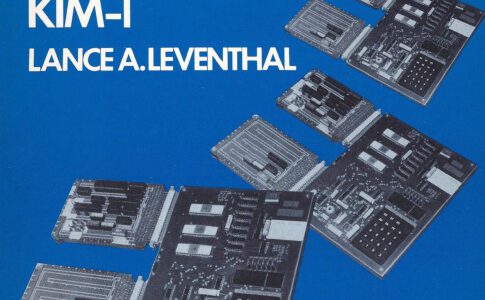
KIM-1
-Display- Blink- und Rollroutinen B1-86
-MRA. Modify Return Address after JSR B1-90
-RAM-Test with Random Patterns B1-93
-ROLDIS – Scrolling Disassembler B1-96
-Alpha-Sort B1-704
-Zahlenwandlung B1-170
-HEADHUNTER B1-122
-STATISTICIAN B1-123
-SUMMARY B1-126
-STRINGHUNTER B1-131
-RALOAD – Relocate after Load B1-133
-Relocate Programs with Header B1-740
-Universal Timer B1-143
-The Lovely Couple of OUICKDUMP and VERSALOAD B1-146
-Transscribe HYPERTAPE to quickDUMP B1-157
-OUICKLOAD Mini B1-758
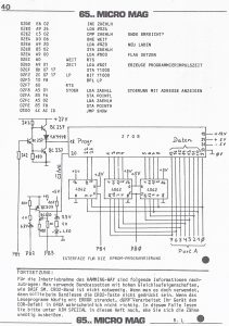
-EPROM-Programmierer KIM-1/2708 B1-760
-Printerprogramm ein Mini-Dot B1-763
-HEXDOT B1-765
-TYDUMP B1-166
-KIM-7 als Störungsanalysator B1-167
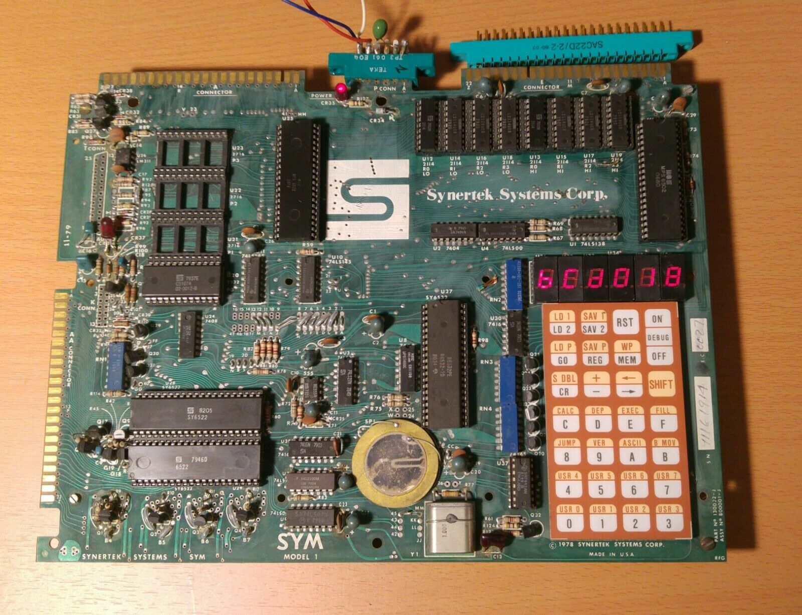
SYM-I
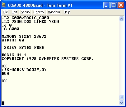
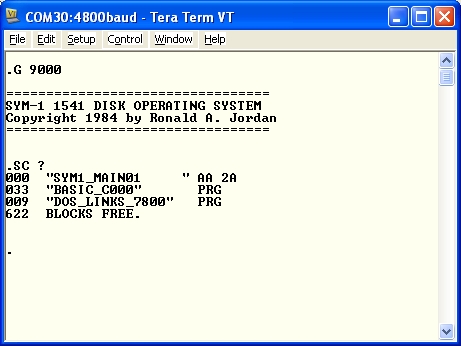
-SYM-I HYPERTAPE-Loader B1-217
-SYM-I, ein Anwenderbericht B1-227
FORTH
-AIM 65 FORTH 16-22
-AIM FORTH V7.3 19-78
-FORTH-Disassembler 19-24
-CBM-FORTH 23-49
-FORTH (1) 24- 3
-Strings für FORTH 25- 3
-FORTH (2) 25-75
-Mengen in FORTH 25-24
-FORTH im Eigenhau (1) 25-30
-FORTH: Befehle für 32-Bit-Zahlen 26- 3
-FORTH (3) 26- 8
-Dynamische Speicherverwaltung in FORTH 26-27
-FORTH im Eigenbau (2) 26-32
-FORTH (4) 27-29
-Cross-Assembler unter FORTH 27-35
-FORTH Turtle-Grafik ein GDP EF 9365 27-37
-FORTH im Eigenbau (3) 27-42
-Ausdruck von Kalendern 28-40
-Multiplikation und Division im FIG-FORTH 28-45
-Makro-Assembler unter FORTH 28-46
-FORTH (5) 28-49
-FORTH mit Fließkomma-Arithmetik 28-57
-FORTH-Splitter (1) 28-52
-Disk-Interface ein FIG-FORTH (CBM) 29-17
-FORTH-Editor 29-19
-FORTH mit Fließkomma-Arithmetik (2) 29-26
-FORTH-Splitter (2) 29-28
-FORTH mit JSR 29-30
-FORTH (6) 29-31
-Gerundete Integer-Quadratwurze1 IS9R 30-60
-FORTH (7) 31-25
-FORTH-Mnemonics? 31-28
-Adreßkartei unter FORTH 31-31
-FORTH-Disassembler 31-35
-FORTH-Splitter (3) 32-57
Produktbesprechungen
-Das VIDEO+ 11-41*
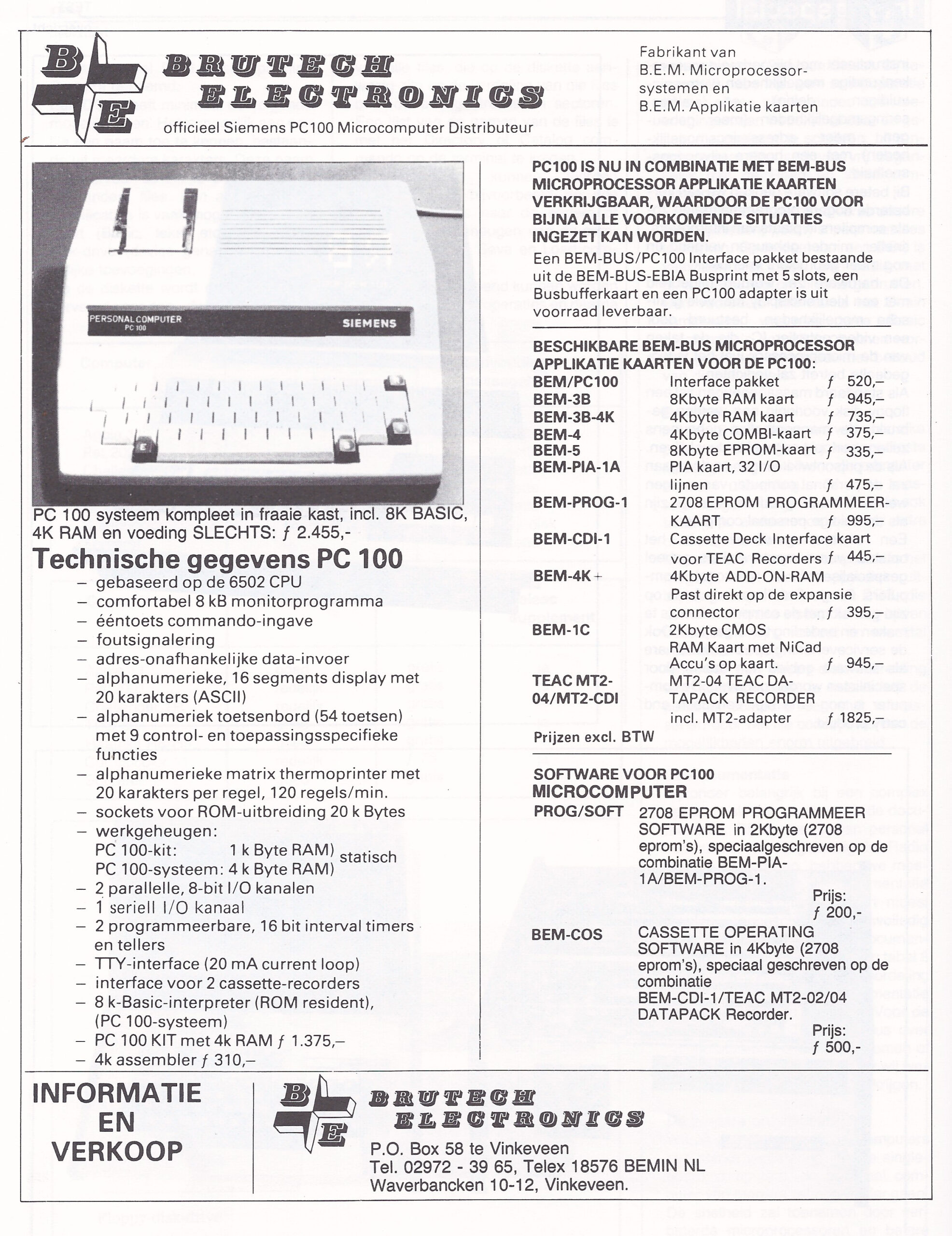
-Vorstellung des Siemens PC 100 10-18*
-Superboard CHALLENGER 1I 11-44*
-Die Challengers von OSI 11-16*
-NEWTIM-S ein CBM 13-26*
-Die neue CBM-Serie 8000 13-41*
-Der AIM 65/40 16-25
-Junior-Computer 16-52
-Video-Interface der Fa. Neudecker 16-49
-Hofer-Drucker 16-49
-Ein g(0)-System 18-43
-DAIM Floppy Disk-System für den AIM 65 18-46
-MatrixdruCker EPSON MX80 F/T 19-49
-12K Basic ein AIM 65/PC 700 19-50
-SM-Kit für CBM 20-59
-Rockwell’s AIM 65/40 23- 3
-Der TRS-80 Color-Computer 23- 9
-Commodore VC-20 23-73
-ISAM ein CBM 23-55
-NEC PC-8023 B-C: ein universeller Drucker 28-53
-FORCE SYS 68K/CPU 1: VMEbus-System mit MC 68000 30-48
-Commodore CBM 710 32- 3
-Heimcomputer: LASER und Aquarius 32-52