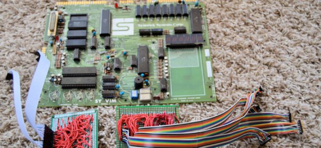
Wayne Parham of Parhamdata has an interesting page on his VIM-1 and SYM-1 systems.
He has written some interesting parts about MS Basic and CC65 C compiler for the SYM-1. reproduced here, credits go to Wayne Parham (the ‘I’ in the text).
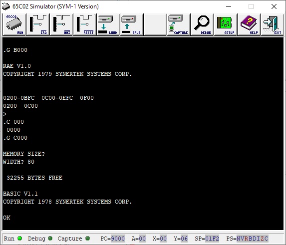
Microsoft 8K Basic on the SYM-1
Most people think Microsoft got its start with Windows. Some know about MS-DOS and the story of its inception. Gates’ deal with IBM to put MS-DOS – and later Windows – on the IBM-PC is definitely the defining moment for Microsoft. It’s what launched them into the juggernaut of success they are today.
But the first Microsoft product was actually 8K BASIC. It was in all the popular microcomputers in the 1970s. They started off making it for the MITS Altair 8800 computer, which had an 8080 microprocessor. And when the 6502 became popular, Microsoft created a version for it. The Apple II, the Commodore Pet and the SYM-1 all had very similar versions of this 8K BASIC.
You can run simple BASIC programs with 4Kb of RAM, but a lot of the “really good programs” need more than that. One in particular that I always loved, was Star Trek. Any time I was at a computer club meeting where someone had a computer with more than 24Kb RAM, they’d be running that game. Just like you could expect to hear Led Zeppelin’s “Stairway to Heaven” or Lynyrd Skynyrd’s “Freebird” in every college dorm and at every party, if you went to a computer club meeting you would see Star Trek running on the head geek’s computer.
So now, with the Corsham Technologies memory board, my SYM-1 could be propelled to the pinnacle of geekdom and run Star Trek.
The problem is there are a lot of versions of the game and most don’t adhere to the 72 characters per line length limit. Some come close though. That’s a problem with many of the popular BASIC programs – there wasn’t a standard back then. Even the language was slightly different between platforms. You had Dartmouth BASIC, the original. Then you had Digital Equipment Corporation’s PDP-11 BASIC and BASIC-PLUS. You had Data General’s Business BASIC. Wang had their own BASIC. Basically, every platform had their own version of BASIC.
Microsoft’s entry of 8K BASIC sort of standardized the microcomputer industry, simply because it was so common. But that was still just another version of BASIC, and the popular “BASIC Computer Games” was actually written for DEC BASIC, so some stuff worked on 8K BASIC and some stuff didn’t.
So I set about finding all the BASIC programs I could find and seeing which would run on the SYM-1. Where I found line length past 72, I modified the program so it would fit. I usually just split the line into two lines. Sometimes, I needed to do a little more. But in most cases, the program is completely original. I’ve noted changes in a README.TXT file in the archive.
Some programs use trigonometric functions, which aren’t included in the 6502 version of Microsoft BASIC. They’re in the other versions of Microsoft BASIC but wouldn’t quite fit into 8K ROM for the 6502. So since these functions are rarely used, they were left out.
Synertek provided code for the TRIG function, which was to be installed in RAM, when needed. I’ve included a version of this code that resides at 9EC7-9FFF in the memory region just above the Monitor ROM. So if you have the CorshamTech memory board, be sure to enable this memory bank. You can then load the TRIG function before loading any BASIC programs that need it.
Alternatively, you can modify BASIC to include the TRIG function and recompile it. The BASIC Interpreter Source for cc65 is available on the pagetable site. It’s assembly code – not C – but the ca65 assembler included in the cc65 distribution will build it. More information on cc65 is shown below.
CC65: C on the SYM-1
When the SYM-1 was introduced, the C language wasn’t very popular. But it became hugely popular, both for systems programming and for things like embedded systems. It has some constructs that are very “close to the machine” that make it perfect for embedded systems. But it has some abstractions that make it easy to write higher-level systems too. So it’s a great language to use.
Still, it was not available for the SYM-1 in the 1970s or 1980s, or for that matter, even in the 1990s. By that time, I had long moved away from the SYM-1, putting it on the shelf for more capable systems. I often used C for embedded controllers in the 1980s, and I still do. I still use C++ for systems programming too. So when I brushed the dust off my SYM-1 and started looking around for stuff to do with it, I was really excited to find the cc65 compiler for the 6502.
I stumbled across the cc65 compiler by finding the BASIC sources mentioned above. The BASIC sources are assembly language, and they are built using the assembler (ca65) and linker (ld65) included with cc65.
I was super-excited to find this compiler, but my excitement paused a bit when I realized that it didn’t have all the files to support a SYM-1. There was memory configuration in the BASIC source distribution that could be used as a basis for the C language configuration though, and the documentation is really good for creating the code needed for a new target system. So I set about doing that.
The cc65 compiler will actually work on the SYM-1 – “right out of the box” – but it can’t support any I/O so it’s not particularly useful. A person can, however, compile a full-featured C program that operates in memory and leaves its results in memory. So all the heavy lifting has already been done by all the contributors of the cc65 project that have made it such an excellent compiler for the 6502.
All I needed to do to complete a port to the SYM-1 was to create a memory map and to provide functions for system I/O. I made functions to access all the SYM-1 I/O lines, the built-in “front panel” display and to direct read and write to the async port so console I/O will work. So I created the (asminc) map of all the important memory locations for monitor access and memory-mapped I/O, wrote little assembly functions for all the I/O and voilà! I had a SYM-1 port for cc65.
One of the first things I noticed – which was actually a no-brainer after seeing it – was that the compiled binary was much smaller when using primitive console functions like getchar(), putchar() and even puts() than it was when using functions that had formatting functionality. The reason is pretty obvious – Code that has to parse and interpret a format specifier is more complex than code that just operates on a single char, or that iterates through a char array. So for example, see the following two “Hello World” code snippets and notice the difference in the compiled executable binary size:
“Hello World” using puts() builds a 526 byte binary:
#include <stdio.h>;

void main (void)
{
   puts( "Hello World!" );
   return;
}
“Hello World” using printf() builds a 2368 byte binary:
#include <stdio.h>;

void main (void)
{
   printf( "Hello World!\n" );
   return;
}
These two programs provide the exact same output.
The second thing I noticed was equally obvious, after actually doing it. I made two memory configurations – one for the “stock” 4kb SYM-1 and a second for a SYM-1 fully populated with RAM. That second memory configuration only uses the bottom 32kb because it is contiguous. So but the stock 4kb configuration provides only 283 bytes of heap storage, whereas the 32kb configuration provides up to 28,187 bytes of heap. I found this by compiling the following program and linking it once using the sym1-4k.cfg file and a second time with the sym1-32k.cfg file. I’ve included both in the SYM-1 distribution of cc65. Of course, since the heap-test program uses printf(), the small memory configuration would have more heap available if it hadn’t.
Understand that the 283 byte limitation on the 4kb configuration is for heap storage. It’s not the total memory available. The compiler allocates memory for the stack, and you’ll probably do everything on the stack when writing a 4kb SYM-1 program. You can do a lot with a 4kb SYM-1 if you are careful with your programming style. I’ve included a few sample programs in the SYM-1 cc65 distribution archive that run just fine in 4kb.
Heap test program:
#include <stdio.h>;
#include <stdlib.h>;
#include <string.h>;

void main (void)
{
   char* buffer;
   int   heap_size;

   heap_size = _heapmaxavail();

   printf( "Heap available is %d bytes.\n", heap_size );

   buffer    = malloc( heap_size );
   memset( buffer, 0x00, sizeof(buffer) );

   if( buffer ) {
      puts( "Memory allocated." );
   }
   else {
      puts( "Couldn't allocate memory." );
   }

   return;
}
You’ll notice that the simple programs above all include , which is fine for console I/O but has no access to the Sym-specific I/O. For that, one would include .
After I had the port completed, I thought I’d better compile some other stuff to make sure it worked. I found a cool little “Adventure” program written by Jeff Tranter. He makes Apple clones and runs cc65 on them. So I compiled his Adventure program and it built and ran first try. I was excited both to know the cc65 compiler was working fine on the SYM-1 and also because I had a cool Adventure program now too! I also compiled Payton Byrd’s port of Wumpus. It requires the time function to randomize – and the SYM-1 doesn’t have a real-time clock – so I removed the time call and instead used an uninitialized int within a function. So just a very small change was needed to get that to compile too.
Now knowing the C compiler was working well, I decided to write a few more programs with it. I always liked John Conway’s life simulator, and it was popular on systems of the SYM-1 era. Even though there was a BASIC version of it, the speed of a compiled executable made a C version of the program more attractive. So I wrote a version of Life in C. Similarly, the Mandelbrot set images were sort of a 1980s thing, but the first ones were primitive ASCII renditions made on minicomputers in the 1970s, so I couldn’t resist but to write a fixed-point integer version of the Mandelbrot program in C. And finally – my pièce de résistance for cc65 on the SYM-1 – was to write a really nice big text adventure game. It doesn’t have the space for the full version of Zork, but it does have enough room for any of the three-part “slices.” Then it occurred to me that even better would be to write something totally new. So I set about making a map and a storyline and Jinx was born.
One more thing – an aside, really – for those of you interested in writing C programs for the SYM-1 or any platform using cc65, for that matter. This is especially true for those of you coding in C++. Most developers today are working with technologies like objects and dependency injection. These approaches are several generations away from the original C, and coding style is much different. What is considered “best practice” today is not really what works best in cc65. For example, most would frown upon using global variables and would prefer to pass variables between functions. But that requires stack operations – pushes and pops – which are expensive operations, especially for a register-limited eight-bit processor like the 6502.
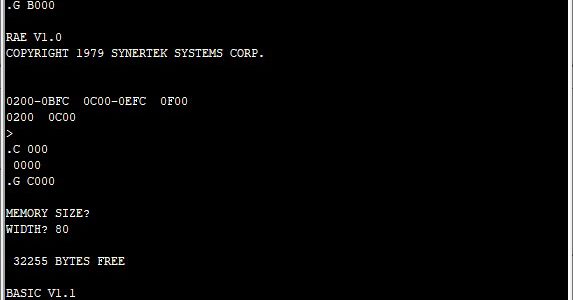
Resident Assembler/Editor
Synertek provided a Resident Assembler/Editor, commonly abbreviated the RAE. It was a bit of an oddball, because Synertek didn’t appear to use it, themselves. It was a ghost of a product, and I can’t recall ever seeing any RAE listings other than those from members of the SYM-1 users group. Even Synertek’s documentation mentions their use of the Teledyn cross-assembler, TASM. The RAE was somewhat popular with members of the SYM-1 users group though.
Still, it was a nice little assembler and an interesting product, so I modified a couple of the programs from Synertek’s Technical Notes (which can be found in the documentation archive) so they would build in the RAE.
I probably should address the issue of transferring the files to the SYM-1. There’s no really easy way to do it, at least not “right out of the box.” You would think you could just copy-and-paste the contents of a program from some text editor like vi or notepad into a terminal emulator program and it would transfer essentially the same as typing it manually. The problem is the SYM-1 has to interpret every keystroke and determine what to do with it, so every character that comes across takes some processing time on the Sym. And since the serial interface has no handshaking signals, the flow must be throttled.
What I found is the transfer of HEX files (for object code) and the transfer of BASIC programs each have their own issues. For HEX files, one must simply throttle the speed of the nibbles, so that there is a slight delay after the two HEX digits that make up a byte are sent. This gives the monitor code time to parse the input and put it in memory. For BASIC, the speed of each character sent is one parameter and the speed of each line is another separate parameter. In other words, each character of a line is throttled by one amount, and then after the carriage return is sent, we have an additional delay. This lets BASIC parse the line and put its tokens into memory.
So I wrote a couple of little Python scripts to do this for me. One is ‘upload’, and the other is ‘upload_hex’. Use ‘upload’ to transfer BASIC files and use ‘upload_hex’ for HEX files. They each take one argument, which is the source file name. The communications port is defined in the code, itself. My system has a USB-to-RS-232 adapter defined as COM3, so that’s what is in the Python script. You can change yours to whatever you need it to be, or modify the script to pass it as a command line argument.
To transfer BASIC files, I first start up BASIC on the SYM-1 then I type ‘upload ‘ on the connected PC. To transfer object code, I first type ‘m 200’ and press enter on the SYM-1, and then I type ‘upload_hex ‘ on the connected PC. It’s a gomer-approach, but it’s pretty reliable. Only occasionally do I get an error – if I see ‘ER xx’ when sending HEX files, I know right away I must do it over – but it works about 80% of the time.
Compilers always write object code as BIN files, sometimes without an extension. If you don’t name ’em, a compiler will even call the file ‘a.out’ so but the point is it is raw binary. To transfer to the SYM-1, it needs to be a hexadecimal representation of the binary, so you will need to run ‘bin2hex’ on the compiled/linked program before transferring it. You can easily find ‘bin2hex’ on the internet.
Another option is this interesting new tool that may make connection with the SYM-1 easier:
Symtool – A tool for interaction with the SYM-1, by Lars Kellogg-Stedman
So you can use whichever upload tool is easiest for you.