Updated December 2020, Linux compilation checked, bugs fixed, online program for comverting binary to wave file.
To aid in the handling of KIM-1 program and dataformats I have written some programs for Windows and Linux (Raspbian), sources included.
KIM-1 simulator
Convert 8 bit hex formats
KIMPaper
KIM Tape WAV to BIN conversion
KIMPoser Tape Convert hex to WAV online
KIM Tape Convert WAV to BIN and BIN to WAV
Pascal-M cross compiler
All programs come with source (Free Pascal Lazarus), compiled for Windows but thanks to Freepascal and Lazarus also compiled and tested on Linux (Ubuntu and Raspberry PI OS).
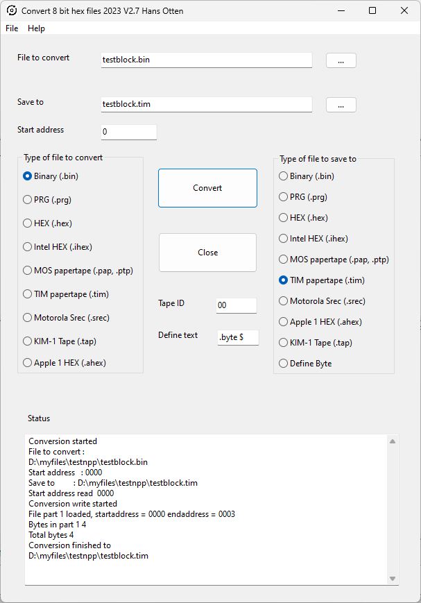
Convert 8 bit hex formats
A general purpose utility to convert common 8 bit hex and binary formats, such as Intel HEX, Motorola S records, MOS Papertape, hex format, and binary files.
Sources (Freepascal Lazarus).
Convert8bithexformat Setup for Windows, Executables for Ubuntu and Raspberry PI OS
Available formats:
– BIN binary, raw data, no formatting, no information on start address.
– HEX formatted as hex numbers raw data, no start address included.
– IHEX Intel hex 8 bit format, multiple memory block, start address included.
– PAP MOS Technology papertape format, multiple memory blocks, start address included.
– SREC Motorola 8 bit S record, contiguous memory block, start address included.
– A1hex Apple Woz monitor hex format, start address included.
– KIM Tape as used in the KIM-1 Simulator as emulation of audio tape files.
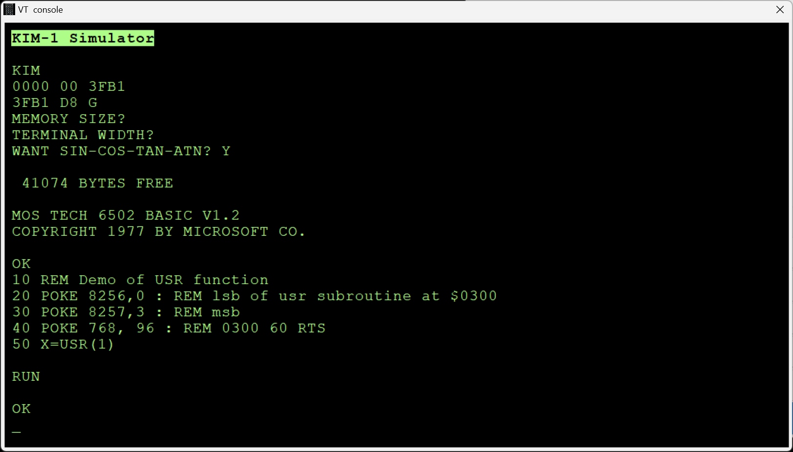
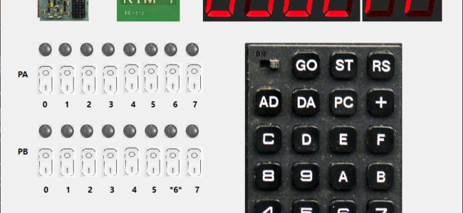
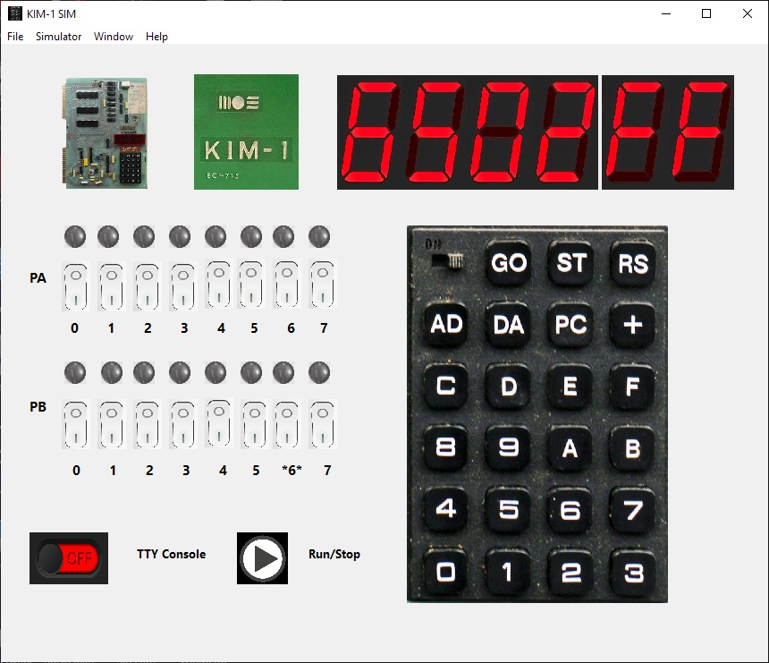
KIM-1 simulator
6502/65C02 CPU emulation, disassembler, TTY, KIM-1 keypad and LEDs.
See the KIM-1 Simulator page for more information.
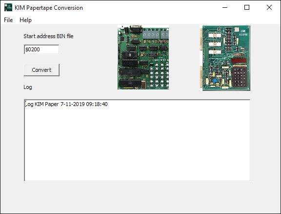
KIM Paper
Note that the Conver8bitHexFormat program is also capable of converting to and from Papertape format from many more formats.
Originally written for the launch of the MicroKIM, an older version is on the support CD.
When you attach a serial device like the teletype or a modern PC with Hyperterminal you can use the TIM monitor of the KIM-1. One of the functions is loading from and saving to a papertape device on the teletype. Now since this is a way to load and save data as a textfile this is in fact quite useful.
The Micro-KIM triggered me to modernize my conversion utility for MOS Technology papertape format dating from 1983, VAX/VMS and Turbo Pascal. A Windows and a commandline/console version are available.
KIMPAPER for Windows
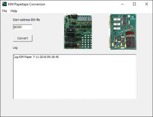
A program for Windows to convert between papertape and binary format.
Windows setup KIMPAPER
Sources (Freepascal Lazarus, build also on Linux)
KIMPAPER V1.1 for DOS
Not too modern, but handy, a commandline utility. Does exactly the same as the Windows program KIMPAPER. Runs fine in a commandline DOS box. Can also be compiled for Linux with Freepascal. In the KIMPAPER DOS archive the program, source and information on the program and papertape format can be found.
C:\MICROKIM\kimpaper
KIM-1 MOS Technology BIN papertape format conversion utility, Hans Otten, 2007 v1.1

Syntax is:
KIMPAPER [-[b|p] filename [startaddress]
C:\MICROKIM\kimpaper -h
KIM-1 Mos Technology BIN papertape format conversion utility, Hans Otten, 2007 v1.1
Syntax is: KIMPAPER [-[b|p|h] filename [startaddress] first parameter switches
-h help
-p convert to papertape
-b convert to binary
second parameter (first if no parameters, assumed binary to papertape)
name of file to convert
.BIN for binary, forces conversion to PAPertape
.PAP for papertape, forces conversion to BINary
third parameter (assumed 0000 if not present)
startaddress for BIN to papertape conversion
Files of type .BIN wil force conversion to papertape.PAP
Files of type .PAP wil force conversion to binary .BIN

Examples:
C:\MICROKIM\kimpaper mastermind.bin 0200
KIM-1 Mos Technology BIN papertape format conversion utility, Hans Otten, 2007 v1.1
C:\MICROKIM>kimpaper mastermind.pap
KIM-1 Mos Technology BIN papertape format conversion utility, Hans Otten, 2007 v1.1
Start address 0200 in file mastermind.BIN
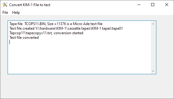
Convert KIM tape to text
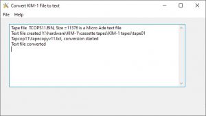
KIM Tape to Text is a utility to convert between binary format of a KIM-1 tape dump to a DOS text file.
The KIM tape dump is a binary file and is just a dump of part of the memory of the KIM-1.
This binary file can be a text file as used in editors Micro Ade or CW Assm/TED.
By using the tape write routine in the KIM-1 one can write an audio file on cassette.
When this audio file is captured on a PC as WAV file (22K, mono) this can be converted back to a binary memory dump with ED’s Utility KIMTape
These text files can be converted to DOS text files with this utility.
First open the binary file. If this is recognized as Micro Ade or CW Moser format, the Save as text file can be used.
Windows program.
Full source for Freepascal and Lazarus, no Windows dependencies. Compiled on 64 bits Windows 10 as 32 bit application.
Note on detection of assembler editor type
1. Micro Ade file must start with CR: when present this is Micro Ade
line nr follows 2 byte
line ends with $0D
file ends with $40
2. Assm/Ted by CW Moser starts with line number $10 $00
end of line is high bit set
There may be rare situations that a file starts with a $0D or a different line nr. You can force CW Mose detection by changing this to a sequence of $10 $00 $0D and if necessary blanks $20 to make it consistent. If in doubts: use an editor that shows the file in hex (Ultra Edit, or the free Notepad ++, Text editor PRO) and study the tape file.
Methods to get the binary file out of a Junior or KIM-1.
Read the record tape into a binary with Ed’s KIMTAPE conversion *see below). It is MS-DOS and runs fine in VDOS (https://www.vdos.info/) or DOsbox (slow).
Make a note of start address as shown by KIMTAPE.
Non-printing ASCII characters are filtered out of the resulting text file.
KIM Tape Convert WAV to BIN and BIN to WAV
Not my program, but so handy!
KIMTAPE v0.5 – tape conversion utility for KIM-1 and SYM-1 (2004-05-17) Local copy of http://dxforth.mirrors.minimaltype.com/#kimtape)
KIMTAPE allows programs stored on cassette tape to be decoded to a program file. It handles both MOS Technology KIM-1 and Synertek SYM-1 tape formats including HYPERTAPE. The reverse process – converting a program file to an audio wavefile is also possible, allowing one to produce perfectly regenerated cassettes. KIMTAPE works with 8-bit mono WAV, VOC or RAW audio files recorded
at 22050 samples per second.
Download: kimtap05.zip (MS-DOS) It is MS-DOS and runs fine in VDOS (https://www.vdos.info/) or DOSbox (slow).
The binary files in the KIM-1 program archives have been reproduced, from the original cassette recordings, with the tool KIMTAPE on a PC in a DOS box. See Eds DX-Forth and Utilities Page for this and other nice programs.
This program also makes it possible to reproduce the original cassette recordings that can be read by a KIM-1.
The files were made as follows: The KIM-1 cassette audio was connected to the PC audio input and (with e.g. Audacity) recorded as a wave file (mono 22KHz).
For example: qchess.wav
The wave file was then converted with KIMTAPE to a binary file (the exact content of of the KIM-1 memory when recorded).
And the KIMTAPE utility then displays load address (for example and tape ID
c:\kimtape qchess.wav qchess.bin
KIMTAPE version 0.5 17-May-04
infile: qchess.wav
outfile: qchess.BIN
Program 01 address 0200 checksum OK xxxx bytes done
This .bin file (any extension is fine!) is NOT a wave file! It contains the exact content of the KIM-1 memory when recorded. The size is exactly the number of bytes as stored in the memory of the KIM-1 and much smaller than the wave file. This binary file can be converted back to a wave file with KIMTAPE or converted to a papertape file with KIMPAPER:
C:\kimtape -M -A0200 -D01 -B2 qchess.bin qchess.wav
As you can see: you have to specify the load address and the program ID. The B parameter indicates hypertape speed (2 here, slow)
The resulting wav file should be acceptable for the KIM-1. It is (as I have tested) acceptable as input for KIMTAPE!
All command parameters can be seen by typing KIMTAPE without parameters:
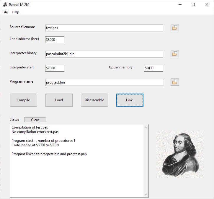
Pascal-M Cross compiler
Executables of cross compiler, workflow, sources, command line utilities.