Contents
Introduction
The Jolt/Superjolt/TIM simulator is written for my personal use to aid me in developing and testing software for the TIM/Jolt/Superjolt. It is not meant to be a cycle exact complete emulation. Instead it shows as much as possible what is happening inside.
Just for fun and a tribute, it looks and feels and functions as a real Jolt or Superjolt. The debugger is what the purpose of this program is. The program is developed on Windows 11 and tested and compiled on Ubuntu, macOS and Raspberry Pi. Since source is available, it will run anywhere Lazarus IDE is available.
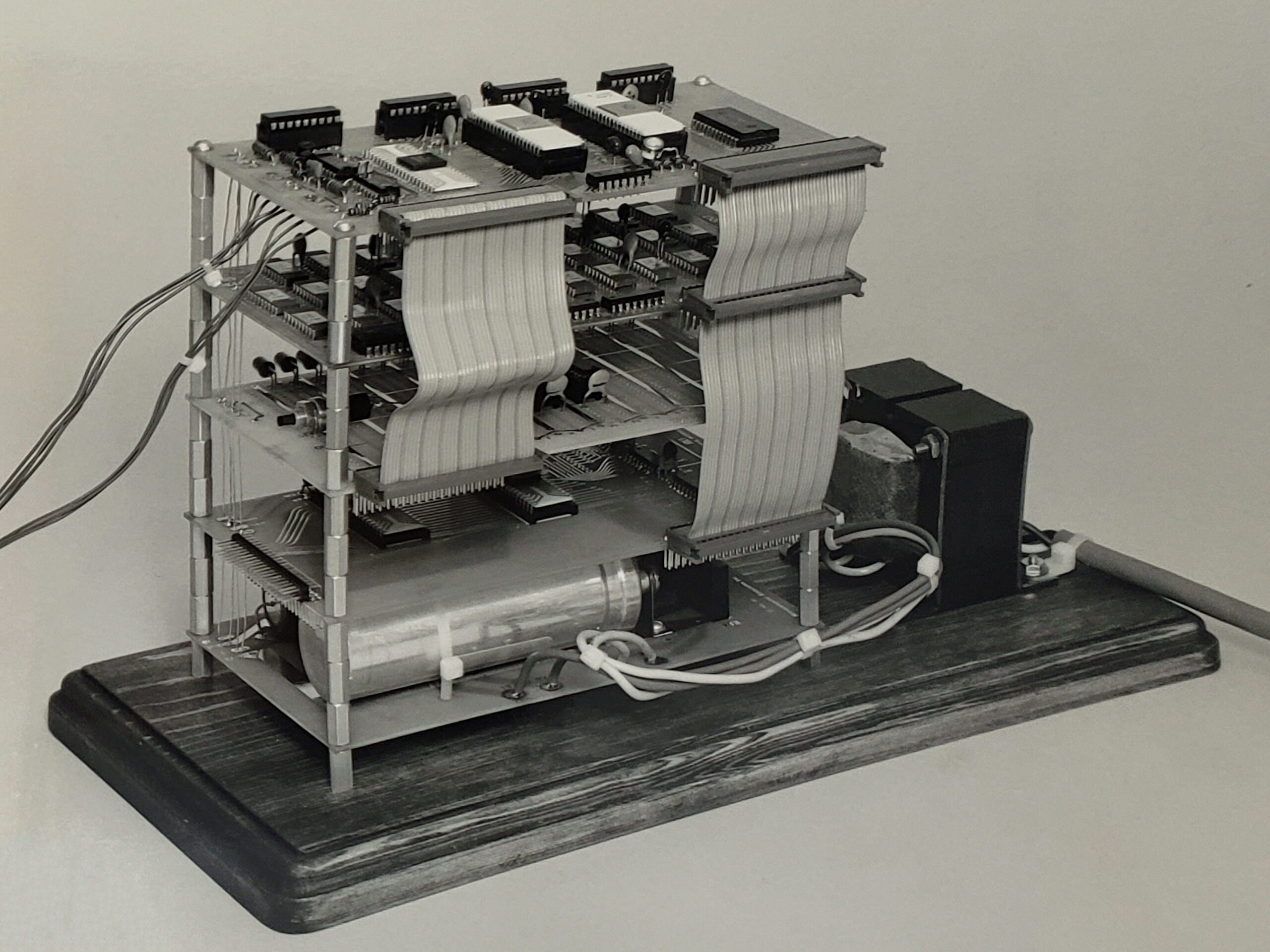
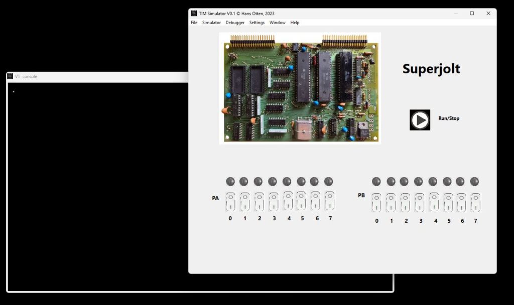
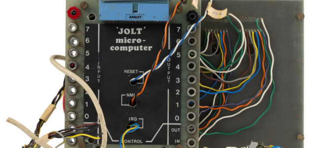
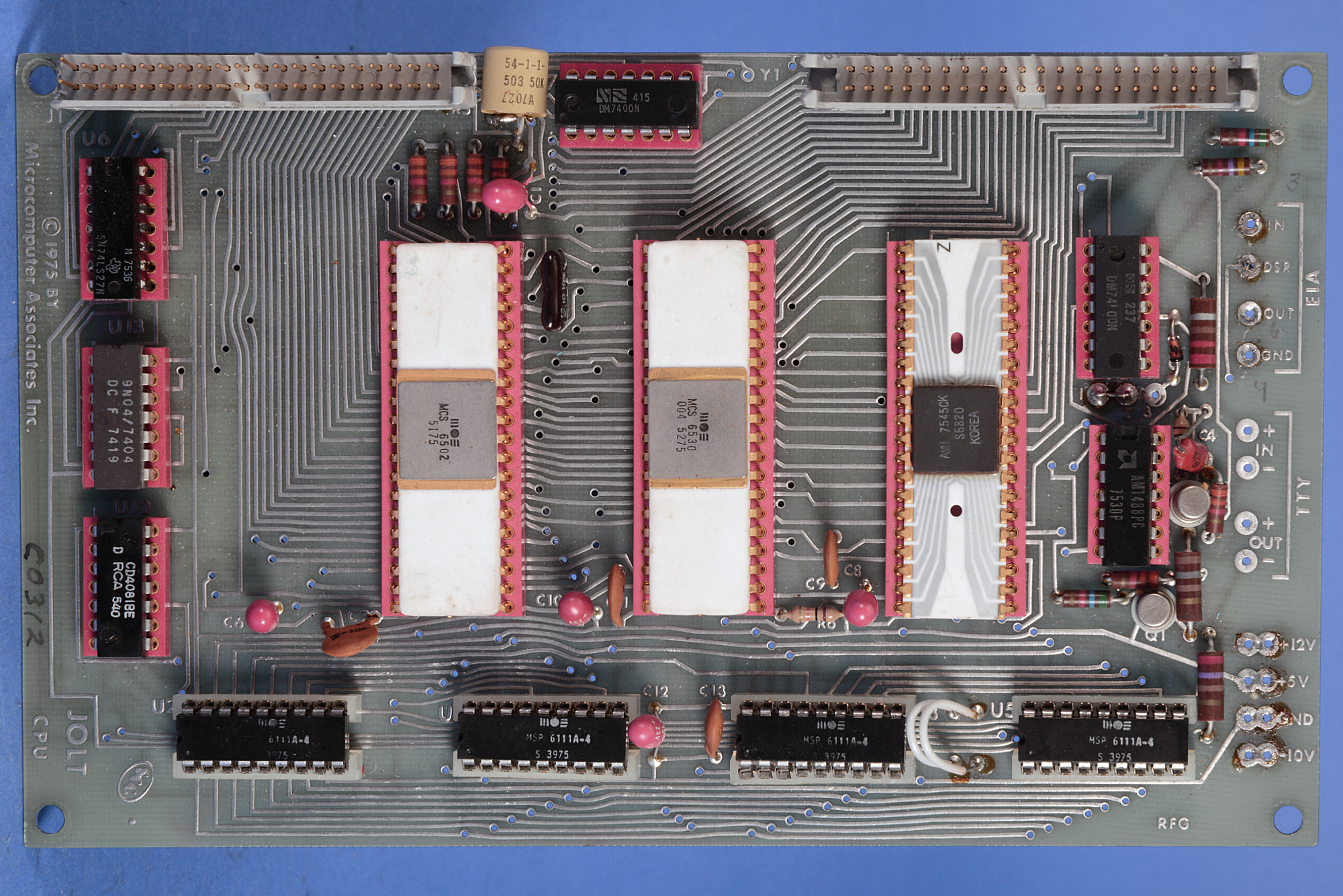
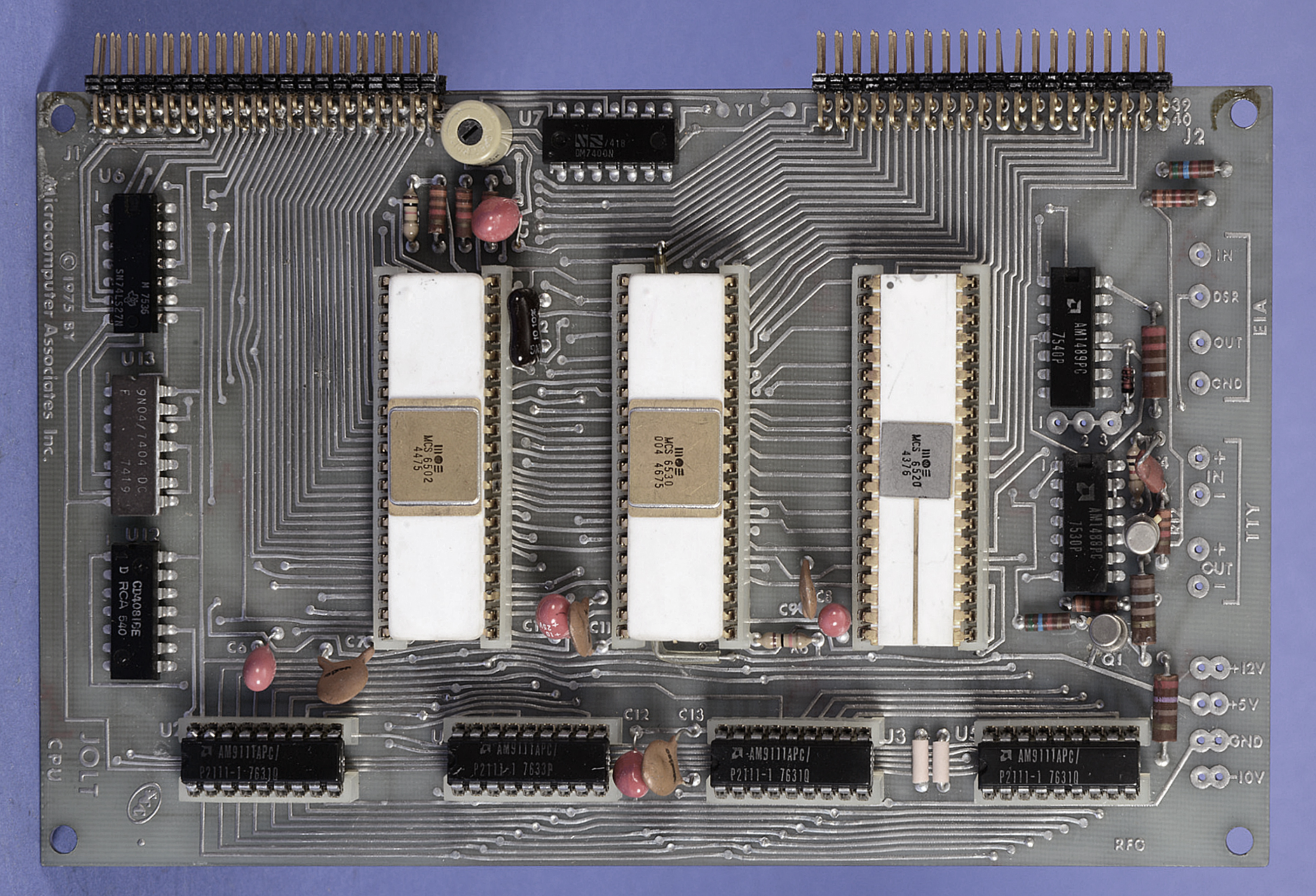
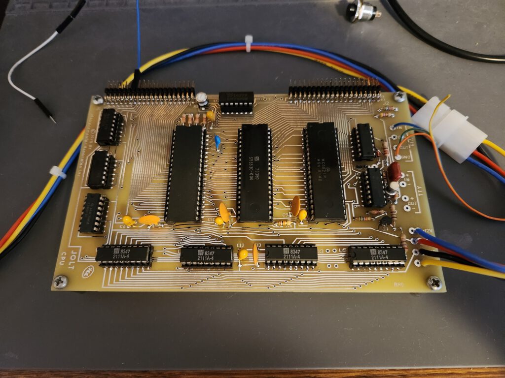
What is simulated looks like a Jolt or Super Jolt or any TIM based computer connected to a videoterminal.
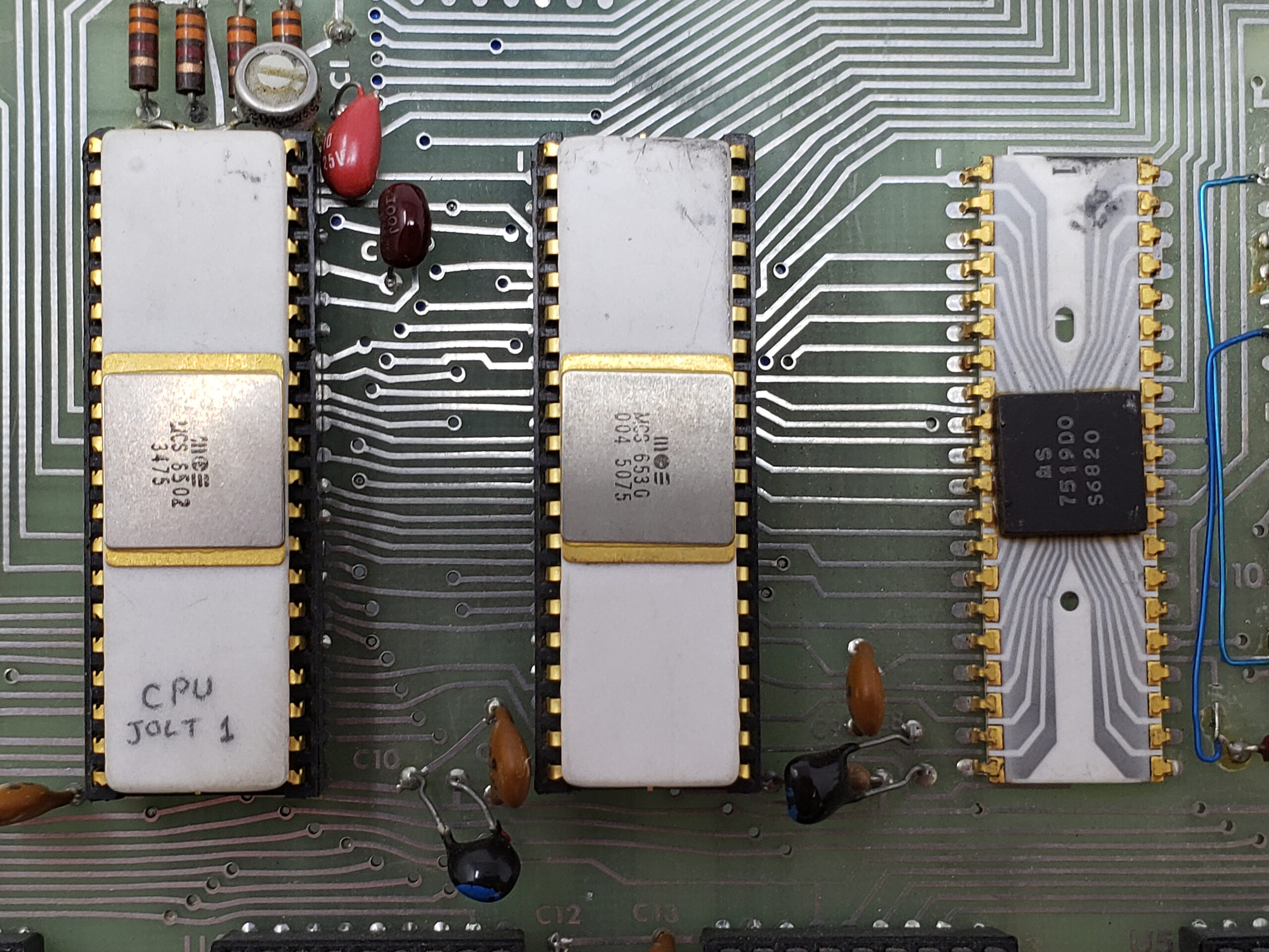
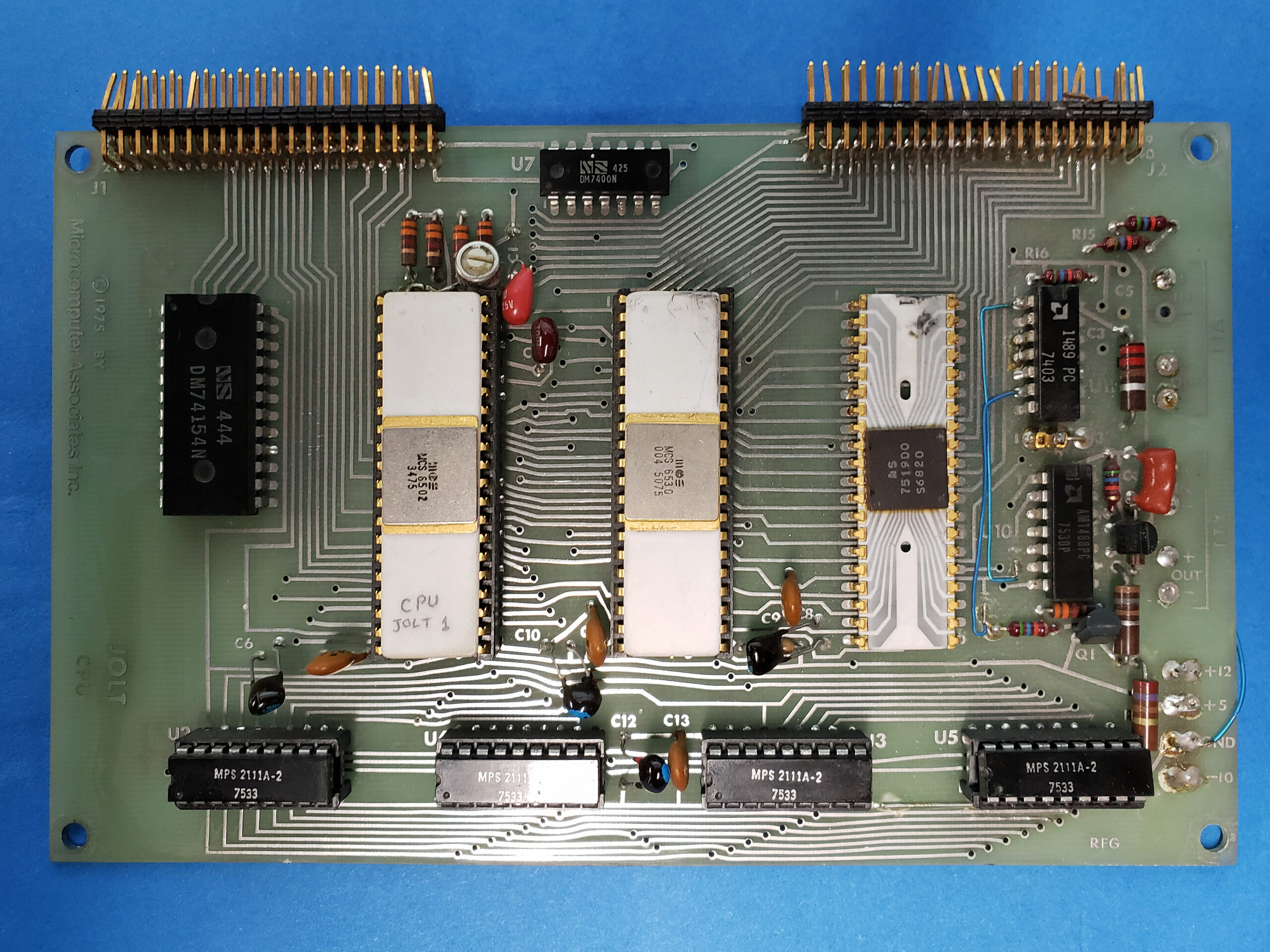
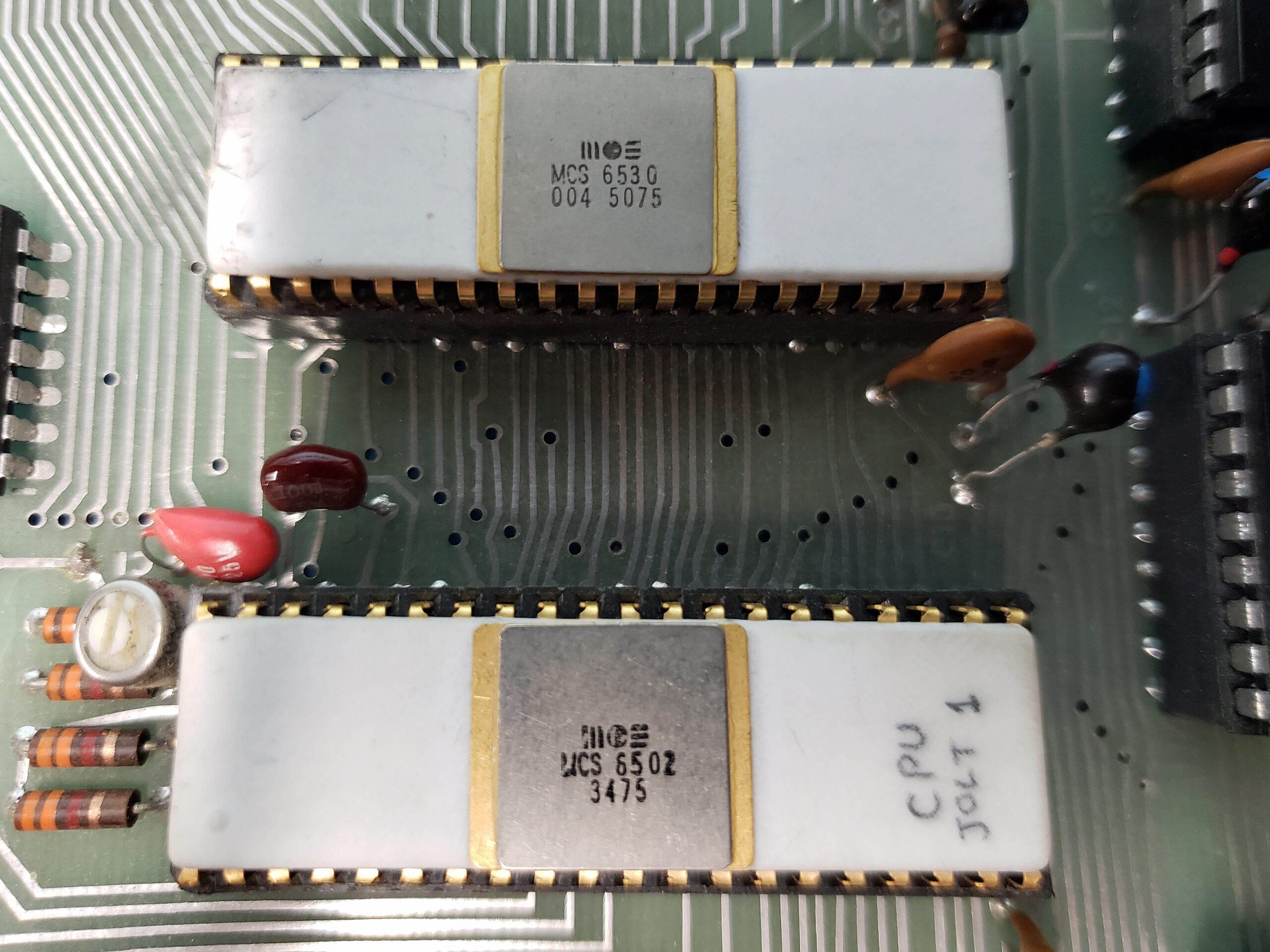
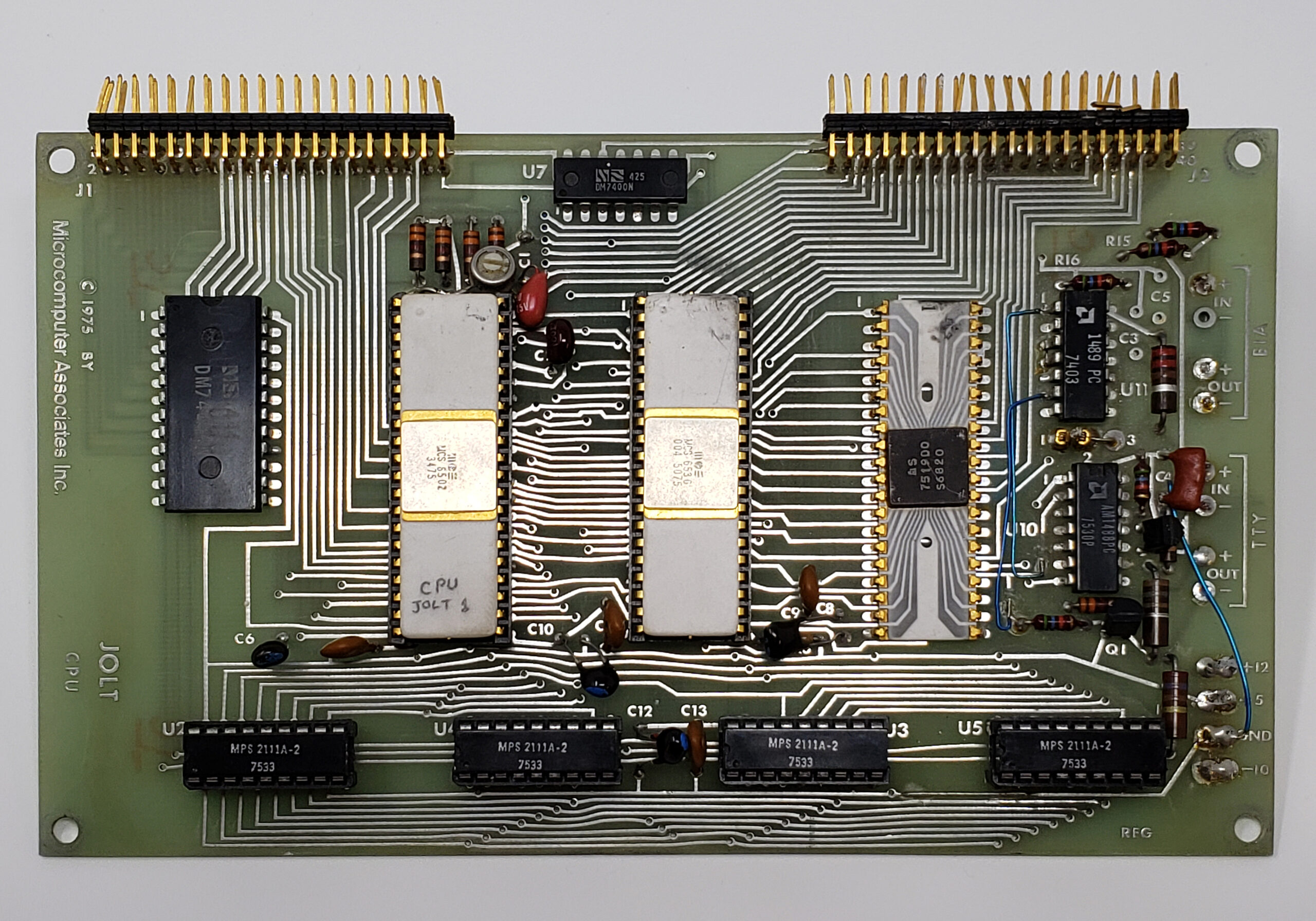
- 6502 or 65C02 CPU (only documented behavior)
- TTY in and out with serial video console or via a serial port
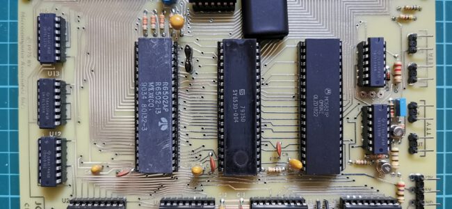
- 6530-004 RRIOT
- A PIA 6821 (not implemented yet)
Limitations
What the TIM Simulator does not do as the real TIM/Superjolt:
- The CPU runs as fast the host CPU allows, and lets the host operating system do some work like key and display and other applications running and continue the emulation loop until the user stops the 6502 CPU.
The speed is herefore dependent on the host CPU. Running the classic Clock program, showing a HHMMSS clock on the LEDs, on my Intel core I7 one minute real time has the clock show 1 hour 37 minutes.
The CPU is halted every 1000 clock ticks to let the GUI of the program a chance to handle mouse and keyboard and screen updates like the stop key.
This works well on modern PCs.
- The CPU emulation may not be perfect, only valid and documented opcodes are implemented, especially ADC and SBC have many, not emulated here, undocumented issues.
- RRIOT emulation does not include the timer
Enhancements
The TIM Simulator is to be a Jolt or Superjolt with:
- 6502 or 65C02 CPU (make the choice in the Debugger)
- RAM to $6000
- 6530-044 TIM RRIOT
- ACIA 6850 at $FE00
- ROM at $F000 with ACIA routines
- Reset, NMI and IRQ buttons
- Tiny Basic and Resident Assembler ROMs
To do, planned expansions
Version 0.1 – 0.9 are beta, only the basic TIM ROM is tested.
- Testing and bugfixing
- Better documentation …
- Add the PIA. The display is already on the main window, but it is not functional
- Add the HS High Speed reader connected to the A port of the 6530-004
Downloads
Bundled with Conversion 8 bit hex formats utility, to convert to/from various binary files like MOS Papertape, Intel Hex, Motorola S-record and more.
Installation
Windows
Run TIMSIMsetup.exe or place the files TIMSIM.EXE file in a folder of choice.
For high DPI screens change the Properties of the TIMSIM.EXE, Compatibility settings,
– Change high DPI settings,
– check high DPI scaling Override,
– scaling performed by “System(enhanced)”.
Ubuntu or Raspberry 5 64 bit
Execute TIMSIM from the Ubuntu or Raspberry Pi folder in the setup archive.
Note that the font used is Courier New. Install ttf cour.ttf on Linux in .home/.fonts to prevent substitution with artifacts
macOS
- Unzip the file
- Move the TIMSIM app to Applications
- Remove quarantine:
$ xattr -dr com.apple.quarantine /Applications/TIMSIM.app
Other platforms
Install Lazarus (Version 2 or higher) and build from source.
You need the Lazserial package from the Package Manager.
No extra packages are required, just standard Lazarus.
Open the project TIMSIM.LPI and do RUN – Build to get an executable.
After installation
Start the TIM Simulator and choose Settings to
– set the default working directory. Otherwise files may appear at locations you do not want!
– Choose between serial or console
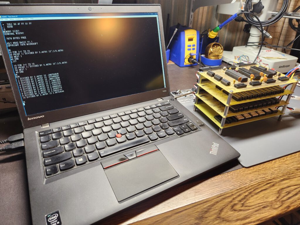
How to use as Jolt/Superjolt
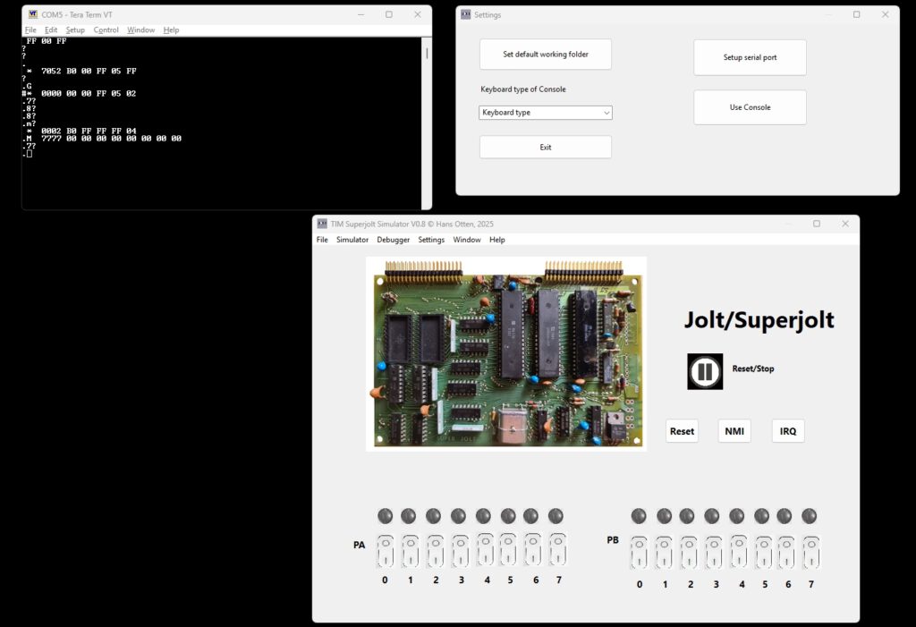
Start the emulator main program and push the ‘Reset/Stop’ icon.
The Console window is the default input/output device for TIMSIM.
Run/stop will display the TIM prompt ‘.’
Default working directory and other settings
Use the menu Settings to display the possible settings that survive sessions.
– Set default work folder to choose a folder for all files created or used by the emulator. The settings are saved between sessions.
Default settings config file : “/home/(user)/.config/TIMSIM.cfg” or C:\users\(user)\Appdata\local\TIMSIM.cfg”
Loaded at startup, updated via the Settings menu.
Load and Save
The menu has Load and Save functions, you can load and save to many 8 bit binary formats as MOS papertape, Intel HEX, Motorola S-record, binary and simple hex.
The 16 bit versions of Intel Hex and Motorola S-Records are not supported.
The Define Type is a text file format suitable for inclusion in assembler source.
The layout is as follows (all in hex)
; <Start address> - <end address>
        <define text> $<hex data>
		 ..
where <define text> is what you fill in the Define text entry, may be empty.

Example:
; 1800-1805
        .byte $A9
        .byte $AD
        .byte $8D
        .byte $EC
        .byte $17
        .byte $A9
a name=”console”>
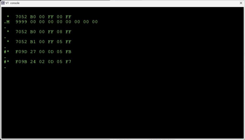
TTY console mode
The TTY console switch lets the TIM simulator use a glass teletype in a console window. The standard TIM user interface is shown, see the manual how to use.
The Console is an emulation video terminal (ANSI color, subset) connected to an ACIA (a Motorola 6850) in the TIM. The TIM Monitor is patched to send or receive via the ACIA and is transparant to the user of the TIM I/O routines (even the quirks like flags and returned register values!)
Note: set the PC keyboard to CAPS Lock, only uppercase is used in the TIM monitor.
Note the menu options to record a session, (Load Text to Console) or play (Save text from Console, followed by Stop saving text ) a text file in the console.
This is in fact the same functionality as a teletype with high speed papertape punch or reader.
Keyboard input, when the console window has focus, is sent to the serial input of the ACIA. No local echo. The TIM monitor only accepts uppercase (hint: Caps lock!), user programs are free to use upper or lowercase.
Characters sent tot to ACIA output are received by the console window and handled as a VT100 would do, a subset of the ANSI/VT100 is implemented.
All keys of the PC are usable, SHIFT works.
Received characters by the console are handled as follows, a subset of the ANSI/VT100 set.
Single control character
$01 : CursorHome
$04 : CursorRight
$05 : CursorUp
BS  : Backspace
TB  : Tab
LF  : LineFeed
FF  : ClearScreen
CR  : CarriageReturn
$13 : CursorLeft
$16 : DeleteToEndofLine
$18 : CursorDown
DEL : Backspace

ESC sequences

ESC[K             Clear from cursor to the end of the line
ESC[0K            Clear from cursor to the end of the line
ESC[1K            Clear from the beginning of the current line to the cursor
ESC[2K            Clear the whole line
ESC[J             Clear the screen from cursor
ESC[0J            Clear the screen from cursor
ESC[1J            Clear the screen until cursor position
ESC[2J            Clear the screen and move the cursor to 0-0, defined sprites are removed, loaded bitmaps are kept

Insert / Delete

ESC[1@            Insert a blank character position (shift line to the right)
ESC[1P            Delete a character position (shift line to the left)
ESC[1L            Insert blank line at current row (shift screen down)
ESC[1M            Delete the current line (shift screen up)

Move cursor

ESC[H             Move to 0-0
ESC[f             Move to 0-0
ESC[s             Save the cursor position
ESC[u             Move cursor to previously saved position
ESC[(Row);(Col)H  Move to row,column
ESC[(Row};(Col)f  Move to row,column
ESC[nA            Move the cursor up n lines
ESC[nB            Move the cursor down n lines
ESC[nC            Move the cursor forward n characters
ESC[nD            Move the cursor backward n characters

Attributes

ESC[m             Reset all attributes
ESC[0m            Reset all attributes
ESC[1m            bold
ESC[4m            underline (overstrike, no room for underline)
ESC[5m            italics
ESC[7m            Turn on reverse color
ESC[27m           Turn off reverse color

Color attributes

color     FG       BG      FG high  BG high
--------------------------------------------
black    ESC[30m  ESC[40m  ESC[90m  ESC[100m
red      ESC[31m  ESC[41m  ESC[91m  ESC[101m
green    ESC[32m  ESC[42m  ESC[92m  ESC[102m
yellow   ESC[33m  ESC[44m  ESC[99m  ESC[103m
blue     ESC[34m  ESC[44m  ESC[94m  ESC[104m
magenta  ESC[35m  ESC[45m  ESC[95m  ESC[105m
cyan     ESC[36m  ESC[46m  ESC[96m  ESC[106m
black    ESC[37m  ESC[47m  ESC[97m  ESC[107m

FG = foreground
BG = background
High = higher intensity

Note that setting colors is implemented in a limited way.
Combining attributes and fore/background in one Escpe sequence is not supported
If you want to use for example

  ESC [1;31;104m (bold, red foreground, blue background)

you will have to use

  ESC[1m  ESC[31m ESC[104m


Printable character (>= $20): placed on screen where the cursor is, cursor moved to next position
Wrap around at end of line, screen scroll up when bottom line is reached
Serial or Console
The TIM Simulator comes with a ‘console’, a glass teletype 24×80 screen. It has a subset of ANSI/VT100 support.
Of course there are much better terminal emulators, like Teraterm, Putty, Coolterm, Minicom etcetera.
And a real VT100 type device is really fun! Or a real Teletype …
Now the Simulator can use either an external serial device,e.g a PC with Teraterm or Minicom, or a terminal emulator locally on the same PC.
The Simulator starts up as usual, with the console window open.
When yo go to the menu Settings you can setup the serial port to use instead of the console for input and output to the Jolt.
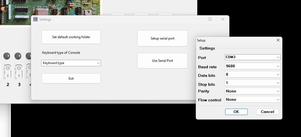
When you next select Use Serial Port, the console window disappears.
Now activate a serial terminal. Extern via the physical serial port (USB etc) or a local one like Teraterm. Make sure the settings are the same as in the Simulator. 9600 baud, 8 bits, no flow control will do fine.
Start the Simulator and the TIM prompt will show on your serial device.
Windows
Install the com0com null-modem emulator from here.
That delivers two COM ports that act as if they are connected via a null modem, anything entered at one is sent to the other and vice versa.
Use a terminal emulator as Teraterm with a serial connection to the other COM port. with the same settings for serial as in the Simulator!
Then select in Settings – Use serial and start the emulator.
Note TIM only works with uppercase characters.
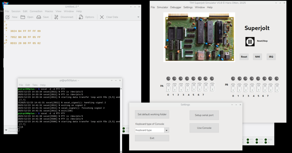
Linux
Use this commmand (install socat if not present).
socat -d -d pty pty
The code above returns (the pts numbers may be different).
2013/11/01 13:47:27 socat[2506] N PTY is /dev/pts/2
2013/11/01 13:47:27 socat[2506] N PTY is /dev/pts/3
2013/11/01 13:47:27 socat[2506] N starting data transfer loop with FDs [3,3] and [5,5]
Any character entered at one is sent to the other pts device as if a null modem cable is connected.
Use the device /dev/pts/2 in the TIM Simulator Settings – Setup serial. Default is 9600.
Start a terminal emulator like minicom or Coolterm and select device /dev/pts/3 at 9600 baud.
Select in Settings – Use serial port /dev/pts/3 and start the terminal emulator.
Now you can control the TIM via minicom or any suitable VT100 like terminal emulator.
Select in Settings – Use serial and start the emulator
Minicom is easy to use. Just set the terminal serial port (the other than the emulator uses).
Coolterm is tested, but is a little bit troublesome to configure.
Force the serial port via Custom and ignore the warning messages.
The debugger
From the menu Simulator choose Debugger to show the debug window. This windows has step/single step/run buttons, shows the registers and flags, zeropage, memory and the stack. The Trace logfile facility may store a trace of what happened.The disassembler part shows a disassembly.
Several refresh buttons let you update the current state of the machine.
Single step, RUN, trace log
First set the PC to the first instruction of the program to test.
- Step in: execute next instruction
- Step over: execute next instruction but skip JSR subroutines
- RUN: execute at maximum speed ( wait 0) or slow (wait x seconds between steps), use the STOP button to halt execution
- Step n: execute n instructions full speed
- Run to: execute instructions full instructions until the breakpoint or watchpoint location is reached or STOP pressed
- You can set 10 code breakpoints, 10 memory watch points and wacthpoints on registers A,X,, Y and Stackpointer, press the Breakpoints and Watches button to show the form to fill in as desired.
- Trace log on/off: first set the Trace log file directory from the file Menu, then use any Step to have every instruction logged with status in the logfile and the tracelog.Note that this slows down execution a lot and the files can become large. So clean up regularly!
The file name of the log is set to TIMSIMtrace(datestamp).log.
Search
From the Search Memory you can Search with hex 1,2 or 3 bytes in memory (leave unwanted fields blank), Fill memory and Copy/Move memory.
With a fill byte you can replace the moved bytes, leave the field empty to leave the original value.
Symbol table and the disassembler
The disassembler shows locations/labels in hex format. If the assembler symbol table is available (TASM can produce that as blank delimited list) you can load it and do some symbolic disassembly.
Load and show the symbol table from the menu “Symbol table”. Supported symbol table formats: TASM 32 bit and CA65 (part of CC65 suite).
The Profiler
Available from the ‘watches and breaks’ form or from the Window menu
This facility keeps track (once activated with the Profiling Check box) how much an instruction is executed,
Independent of the debugger, always available.
Use the Refresh button to see the current state, not automatically updated so it is no a high performance hit.
Any opcode, from o to 255, is counted. The display shows the maximum 65C02 instruction set.
You can save the profiler data to a CSV file, with instruction mnemonic and number of times executed per line.
Invalid instructions are marked as ‘Unknown’.
Compiling and building the simulator from source
Prerequisites
- A modern PC and operating system. Windows 10/11 is where the software has been developed, R Ubuntu has been tested.
- Development (Compile and run everywhere!) with Freepascal and Lazarus IDE, see https://www.lazarus-ide.org/
Any Lazarus version above 2.0 will be OK.
- The archive with the TIM Simulator sources TIMSIMs09.zip (or higher version).
- Unpack in a folder, avoid blanks in folder and filenames
- Start the IDE by clicking on TIMSIM.lpi
- Build with Run – Build
- On Windows a Setup installable can be made with Inno Setup, TIMSIM.iss and compile with Inno Studio.
Note that the font used is Courier New. Install ttf cour.ttf on Linux in .home/pi/.fonts to prevent substitution with artefacts
The include files with TIM ROM and 6502 code
If and when the ACIA routines and other routines in the TIMSIM ROM are altered you need to rebuild the TIMSIMrom.inc file.
Subfolder ‘romtoconst’ contains the binary of the original TIM ROMS (TIM.bin) and the additional ROM binary with ACIA routines (timsimrom.bin).
The .inc files for the compilation of the TIMSIM, to be placed in the main folder, are created with the program creatINC.exe, a console application (source included here).
Copy the the tree .inc files to the main folder and compile the TIMSIM program again.
Tiny Basic and RAP are in joltsw.bin
D:\myfiles\development\TIM simulator\romtoconst\creatINC.exe
timsimrom.inc include file created
timrom.inc include file created
joltsw.inc include file created
Folder TIM assembler sources
with command to create intel hex file
"D:\myfiles\development\TIM simulator\TIM assembler sources\tasm" -65 -x3 -g0 -s $(FILE_NAME) $(NAME_PART).ihex $(NAME_PART).lst -s $(NAME_PART).sym
or to create a binary file with
"D:\myfiles\development\TIM simulator\TIM assembler sources\tasm" -65 -x3 -g3 -s $(FILE_NAME) $(NAME_PART).bin $(NAME_PART).lst -s $(NAME_PART).sym
Note that also symbol files are generated which can be read in by the debugger in the TIM Simulator.
Changelog
- V 0.1 21 November 2023 First public beta
- V 0.2 22 November 2023 File load/save menu repaired
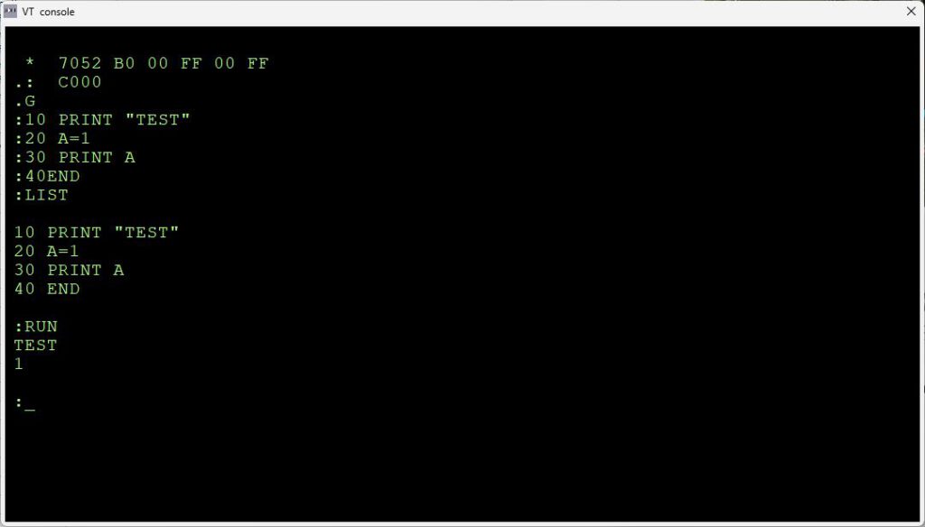
- V0.3 26 november 2023 Tiny Basic runs, console limited to ASCII to $7E, bit 8 masked off
Break condition now always false (Tiny Basic spits out rubbish) Backported to KIM-1 Simulator.
- V 0.4 1 December 2023 Tiny Basic corrected in ROM, TIM ROM corrected for LH ; error, forms now on taskbar Windows
- V 0.5 File types shown in load/save, bugfixes, setup with logo
- V 0.6 Console improvements
- v0.7 November 2024 Support ACIA ROM moved to F800.
Can now load KIM-5 Resident Asembler/Editor
- 0.8 Serial input/output added
- 0.9 Online help and general local keyboard support