Scott LaBombard started many years ago on a replica of the Jolt. Quite a challenge, since only photos are known.
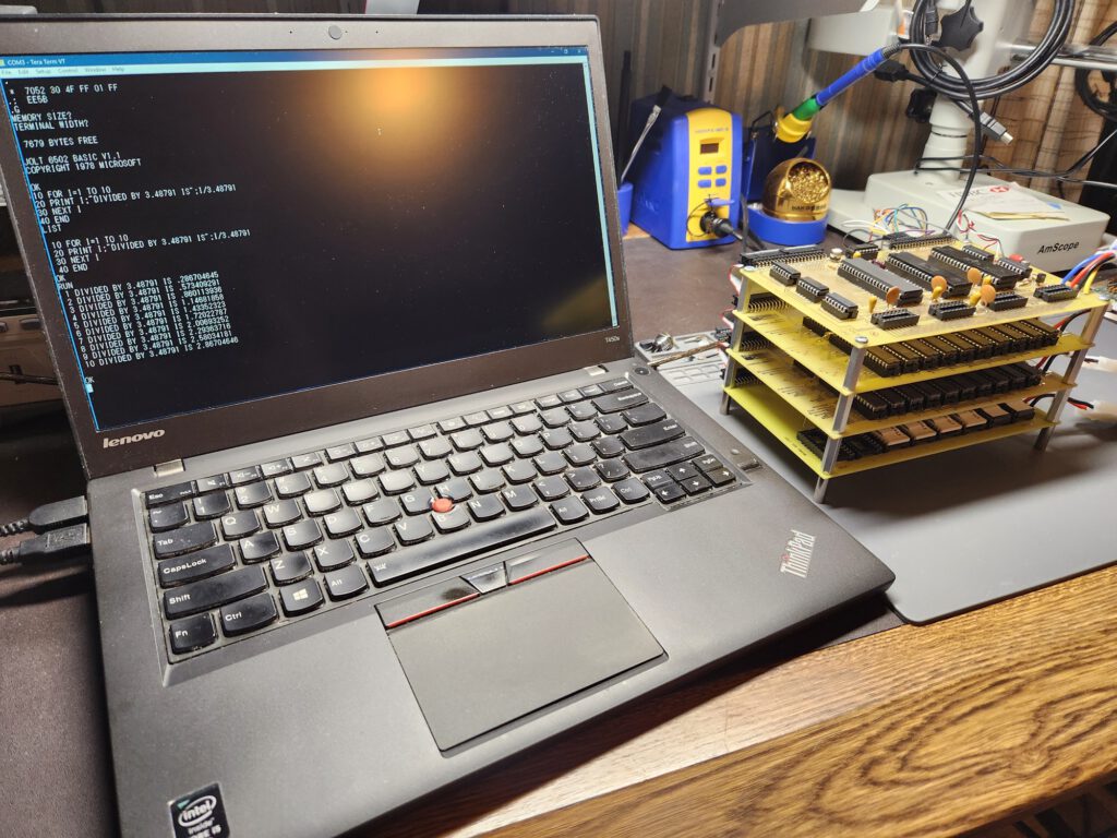
He succeeded in finishing a working replica as shown in the next photos sent by Scott.
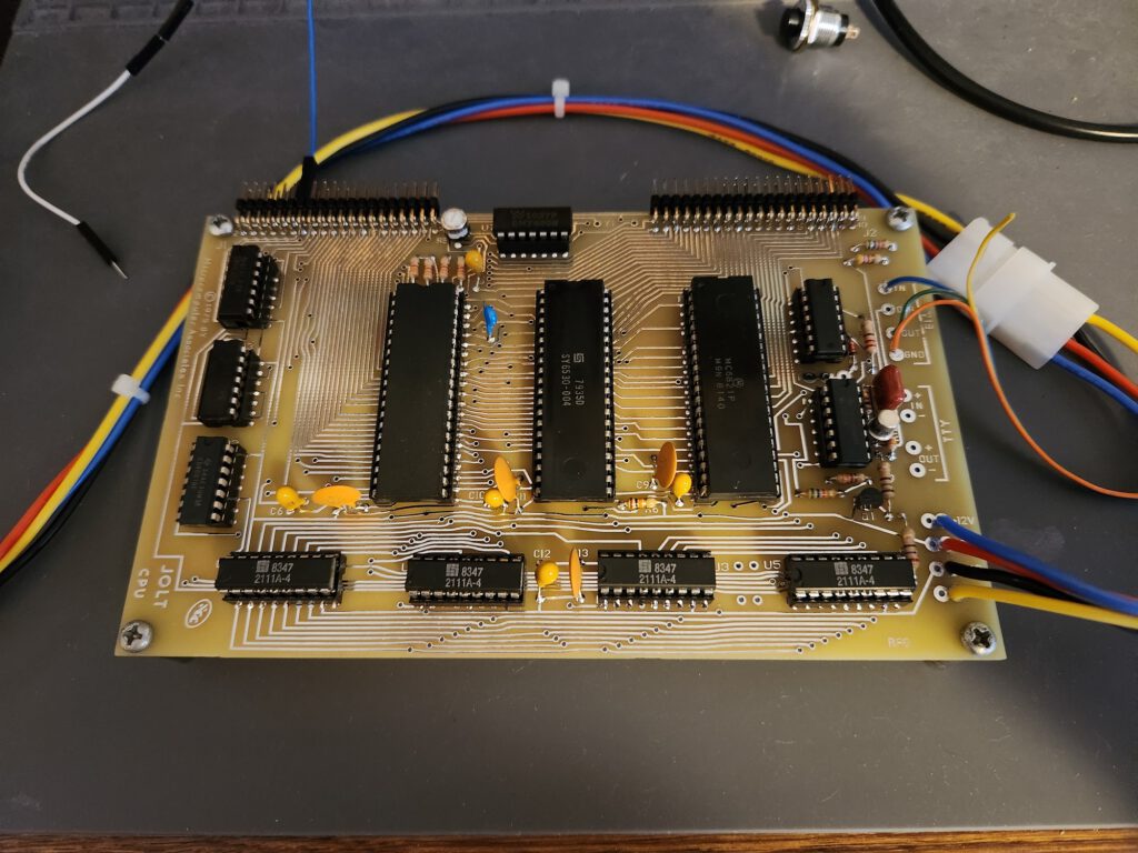
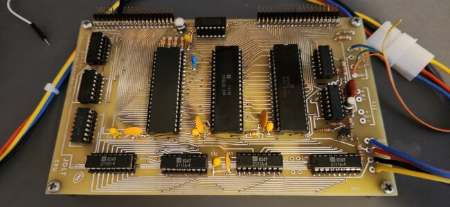
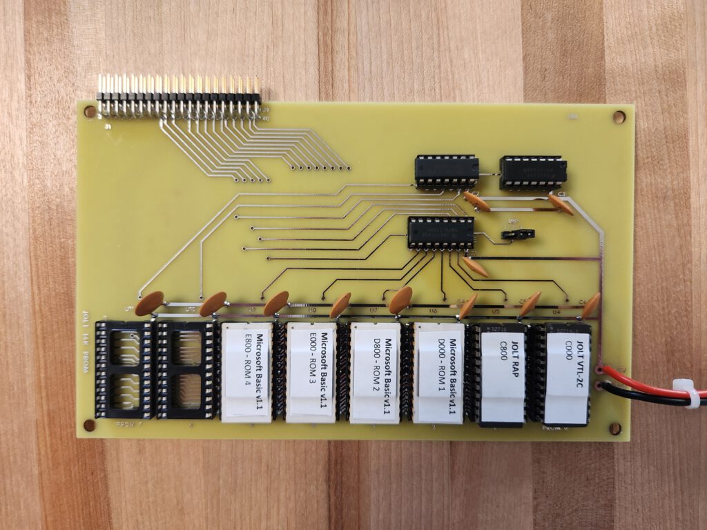
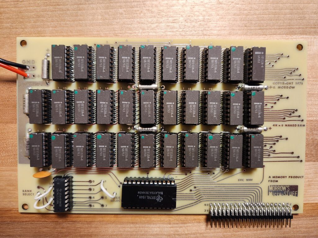
Attached is a picture showing the Jolt ‘stack’ running a late iteration of Microsoft’s 6502 Basic that Scott ‘ported’ to the Jolt. He even have it configured to support integer arrays and extended precision. Also included a picture of a replica of the George Morrow ‘naked’ 4k RAM board that was specifically marketed for Jolt owners back in the day (two are installed in the stack for 8k total). Last, there’s a picture of Scott’s own design of a 16K eprom board based on the mostly period correct 2716 eprom. It is jumper selectable for a base address of $8000 or $C000 (when configured for $C000, it only decodes $C000 – $EFFF because the Jolt decodes $Fxxx). One could install 28K of eprom with two of these boards!
In addition to Microsoft Basic, the eprom board has VTL-2 (Very Tiny Language) that is also ported to the Jolt. And last but not least, the eprom board has MAI’s RAP installed as well.
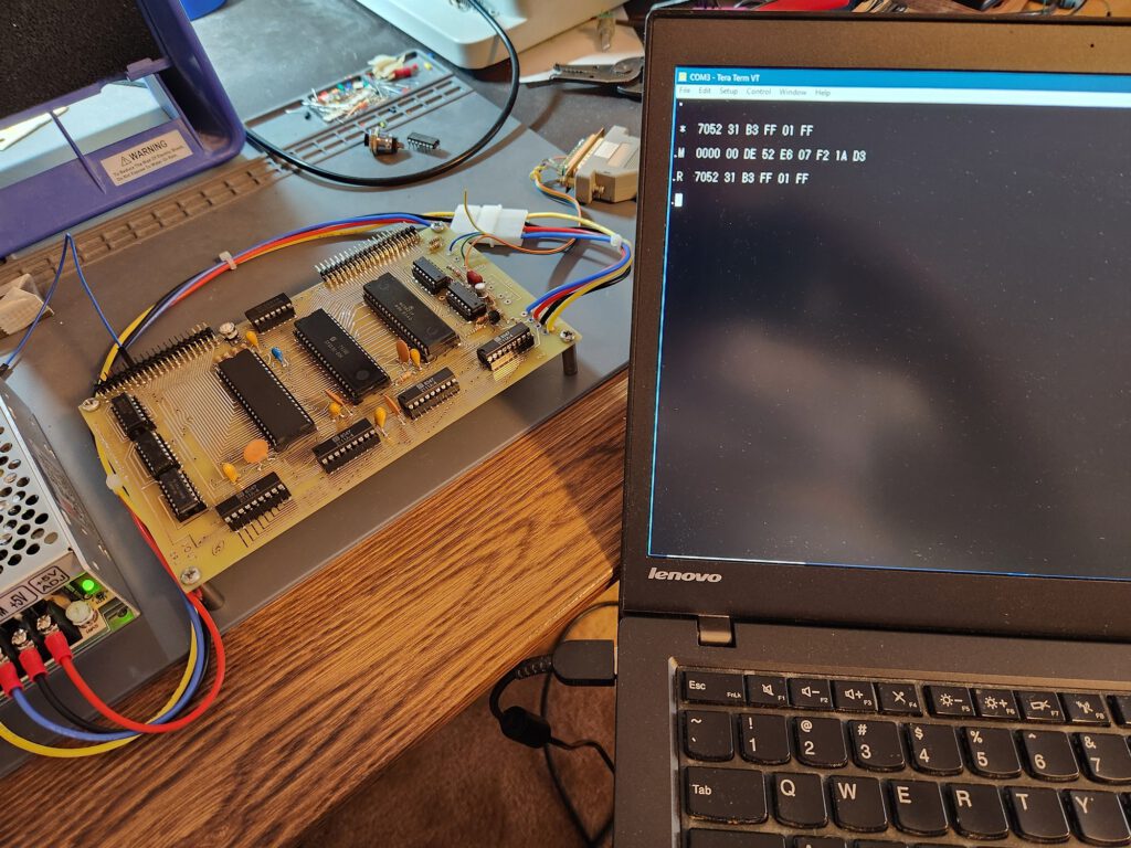
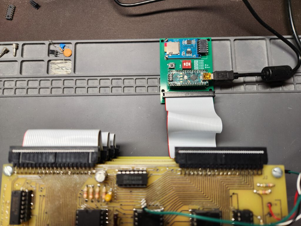
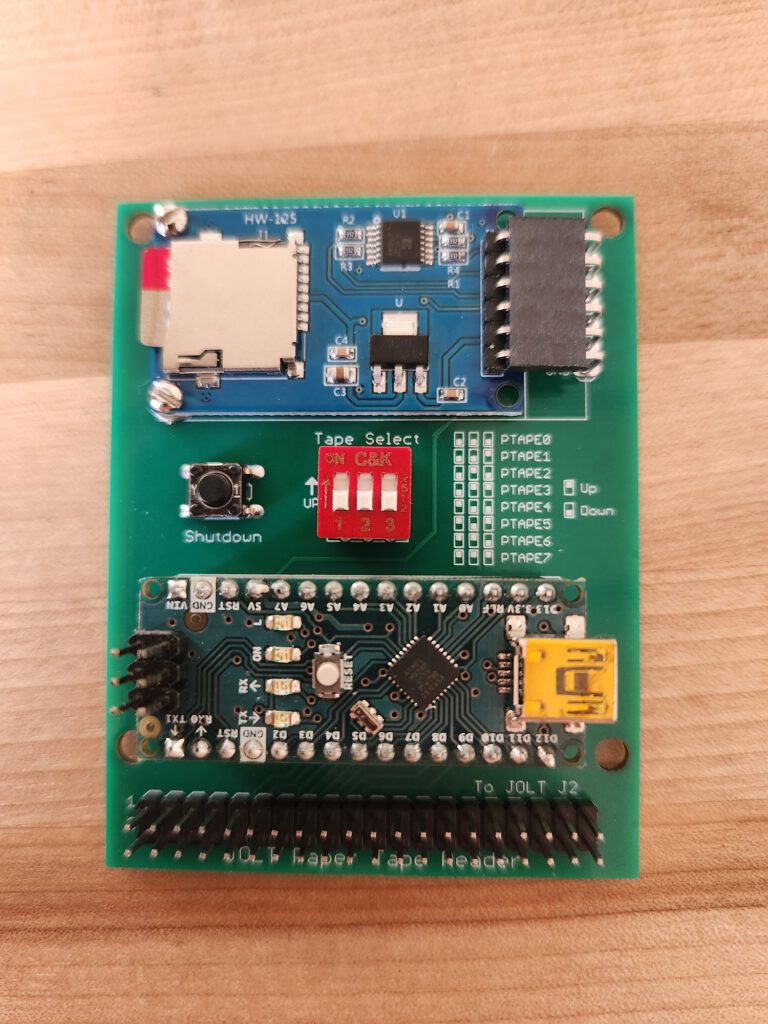
You may notice some wires hanging off from the J2 connector, that is connected to a ‘high speed tape reader’ that Scott designed specifically for the Jolt. It works directly with the TIM monitor just as documented (using the ‘H’ command to switch to the high speed tape reader, and then ‘LH’ to load ‘tapes’ in MOS Technology hex format). It’s super fast compared to loading via the console.
Scott has also created replicas of the original 2K eprom board that uses the venerable 1702 eproms, as well as the original power supply board.
He also did a replica of a George Morrow Micro-Stuff “Naked” 4K RAM board that was primarily marketed for the Jolt as an alternative to the original Jolt 4K RAM board.
+++++++++++++++++++++++++++++++++++++++++++++++++++++++++
JOLT TinyBasic Enhancement ROM Notes
Scott LaBombard
August 2025
+++++++++++++++++++++++++++++++++++++++++++++++++++++++++

Just add the ROM at $D000. No SW/HW modifications are
required.

Commands added: MON, HSPTR, NEW, AND, OR, NOT, PEEK, POKE
                ABS, FRE, FOR, NEXT, LOAD, and SAVE
+++++++++++++++++++++++++++++++++++++++++++++++++++++++++

AND
example:  PRINT AND(125,589)
output:   77

OR
example:  PRINT OR(125,589)
output:   637

NOT
example:  PRINT NOT(43)
output:   -44

ABS
example:  PRINT ABS(-43)
output:   43

FRE
Prints free memory.
Usage:    PRINT FRE(0)

HSPTR
Toggles between using the high speed paper-tape reader
or the console for input.

NEW
Clears the current program.

PEEK
Print the contents of the specified decimal memory address.
example:  PRINT PEEK(8192)

POKE
Store the specified value at the specified memory address.
example:  POKE 8192,44
result:   value 44 will be stored at address 8192

PEEK
example:  PRINT PEEK(8192)
output:   44

FOR/NEXT
Standard FOR/NEXT loop support. STEP is not supported,
however reverse order loops are:
FOR I=1 TO 10      FOR I=10 TO 1
PRINT I            PRINT I
NEXT I             NEXT I
END                END

SAVE
Will save the current Basic program in MOS Tech Hex format
to the console. After entering the SAVE command, you will
be at the TIM monitor prompt.

After the SAVE command has finished, you will be at the
TIM monitor prompt. Just enter the TIM 'G' command to
return to TinyBasic (via the TinyBasic warm start entry
point, so the Basic program remains intact).

LOAD
Will load a Basic program in MOS Tech Hex format from the
console or the high speed paper-tape reader (depending on
which is selected for program input by the HSPTR command
or via the TIM monitor's H command).
After the LOAD command has finished, you will be at the
TIM monitor prompt. Just enter the TIM 'G' command to
return to TinyBasic (via the TinyBasic warm start entry
point, so the Basic program remains intact).
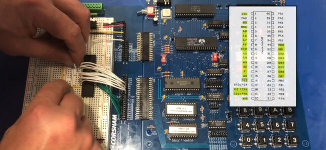
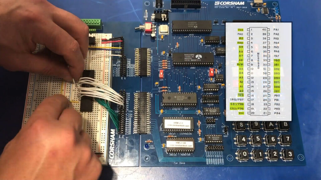
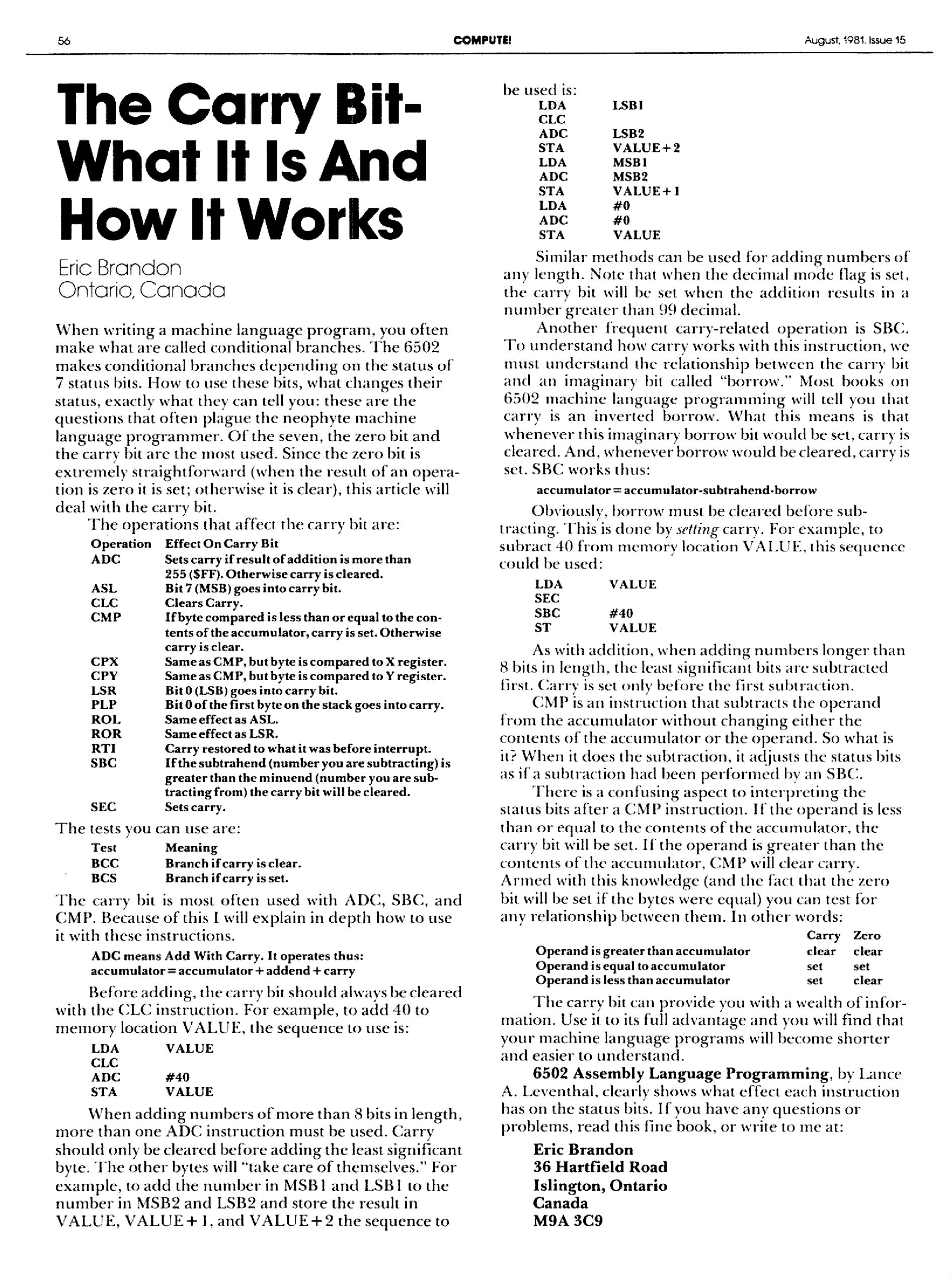
A 6530 IC is to be used in a 6502 computer as standard 65XX peripheral.
Two of the tests on the next pages are breadboard tests on a KIM-1 (clone)>
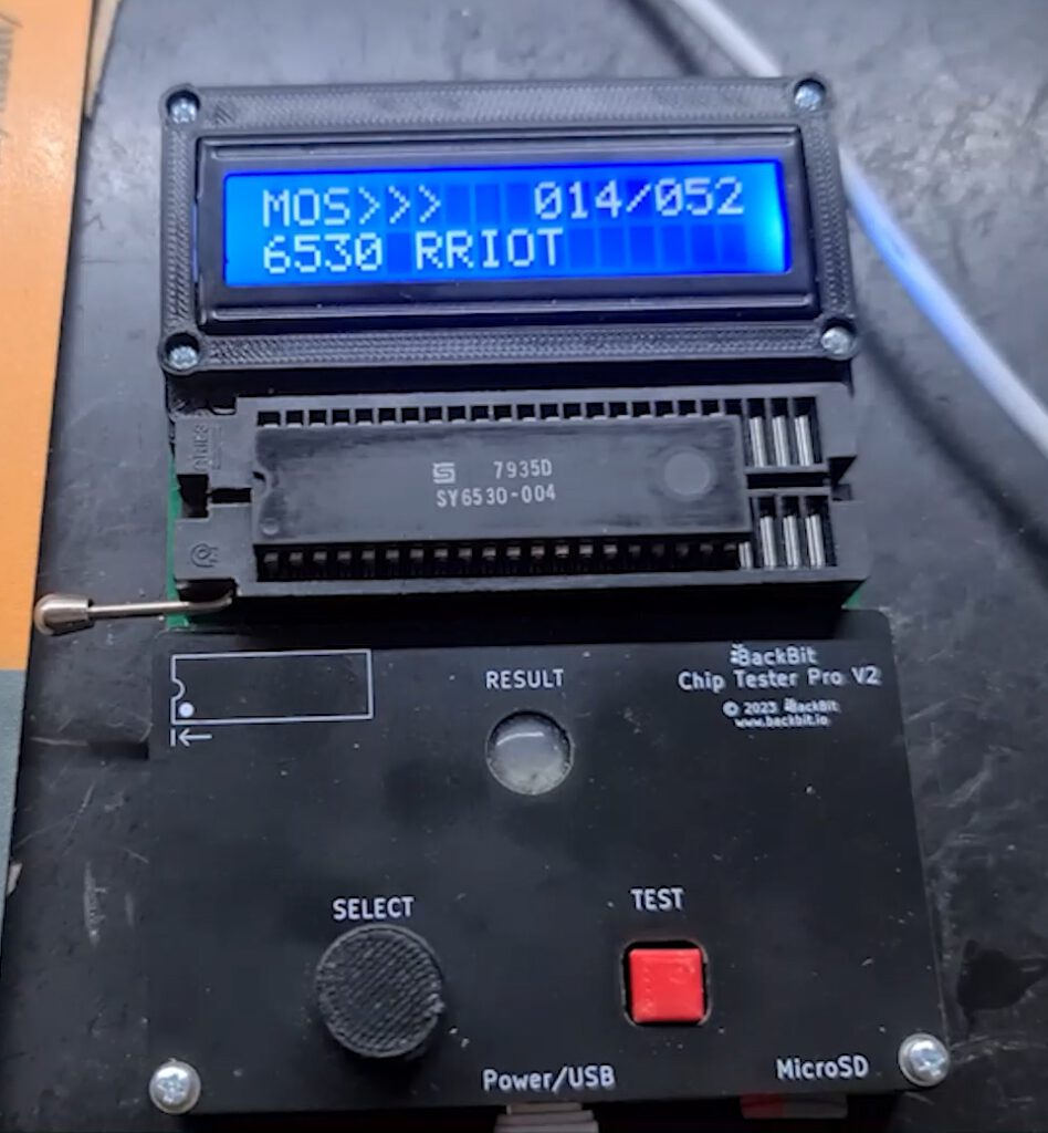
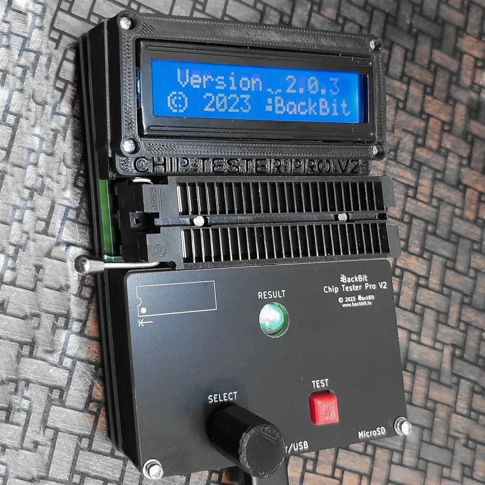
The first test is the simplest and fastest: the excellent Backbit Chip Tester Pro for a test and ROM dumps
I have a small collection of the MOS 6530 RRIOTs as made by MOS Technology.
Mask programmed, ROM and also ports can be used as chip select. See the 6530 pages!
6530-002 black all tests passed and ROM dumped OK, confirmed to be the 002 ROM, main KIM-1
6530-002 ceramic all tests passed, ROM test fails
6530-003 black all tests passed and ROM dumped OK, confirmed to be the 003 ROM, audio cassette KIM-1
4x 6530-004 all tests passed, except the PORT B and no ROM dumped, TIM
3x 6530-005 all tests passed, except the PORT B and the ROM (which is to be expected, the 005 has no ROM)
2x R6530P/R3004-11 all tests passed, except the PORT B and no ROM dumped, pinball
2x 6530-24 all tests passed a except the PORT B and no ROM dumped, Commodore diskdrives
I also tested a 6530 replacement, built with a 6532 and some glue logic and an EEPROM, both 002 and 003 variants tested OK.
SO I suppose all these 6530’s except the ceramic 6530-002 are all right. The Port B test fails, since the 6530-002 and 6530-002 use pin PB6 for a chip select and the others may have this as I/O pin. Now waiting for an answer of the Backbit Chiptester Pro to my query about Port 2 testing.
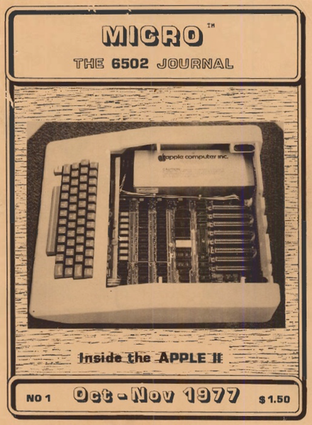
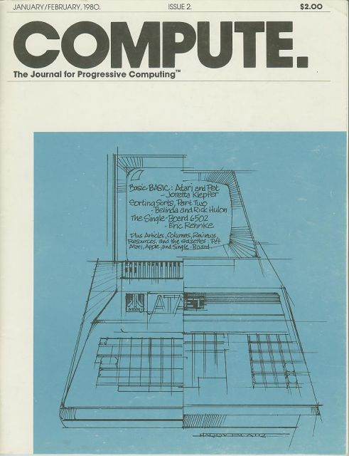
Published by Robert M. Tripp, The Computerist
Published from 1977 tot 1983. The first years many KIM-1/SYM-1/AIM-65 articles, slowly faded to Apple Atari etc in later years, and ended in 1984. The whole archive is here.
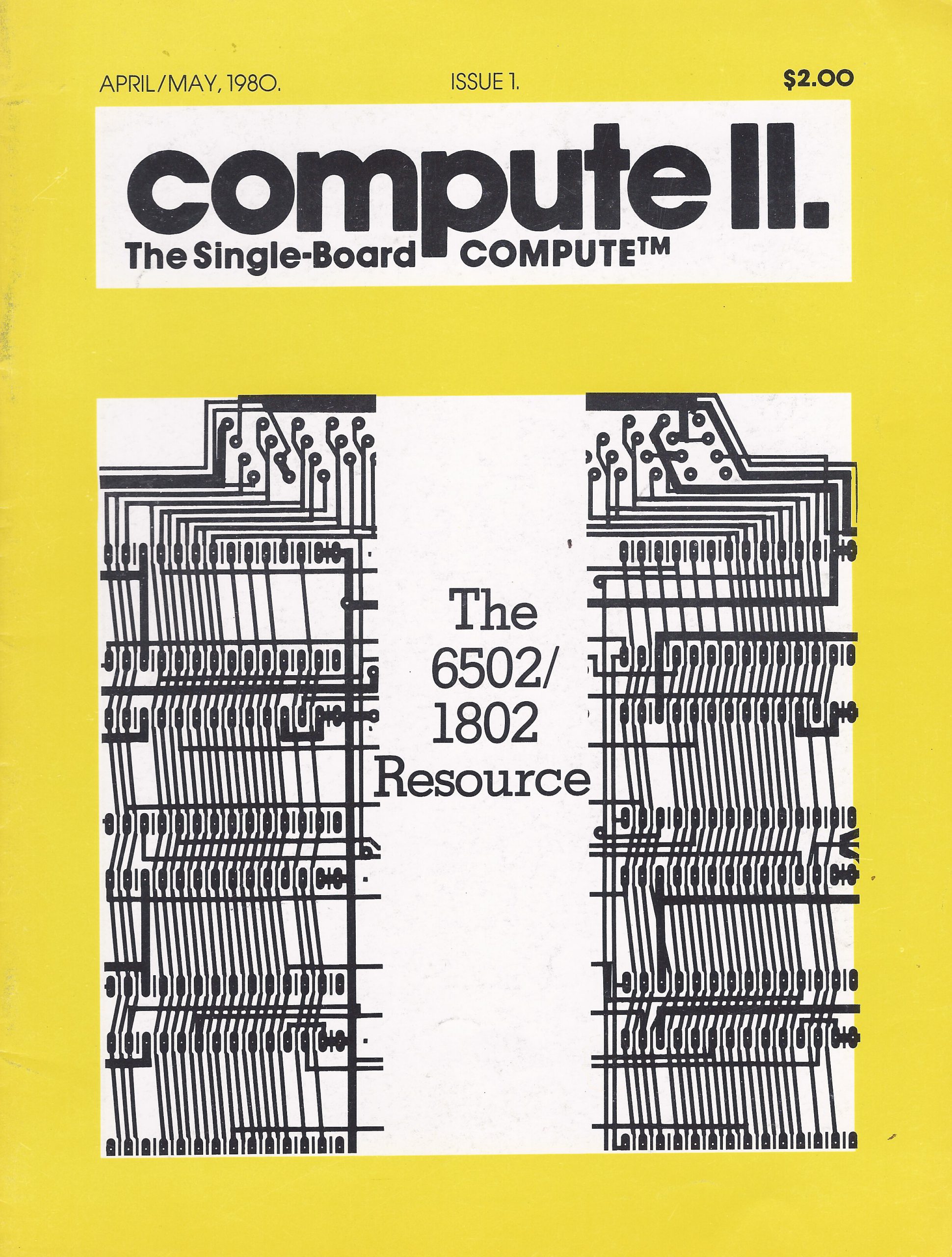
Compute II was a short lived split-off of Compute! and also a continuation of the KIM-1/6502 User Notes. Three issues and it was merged back with Compute! again.
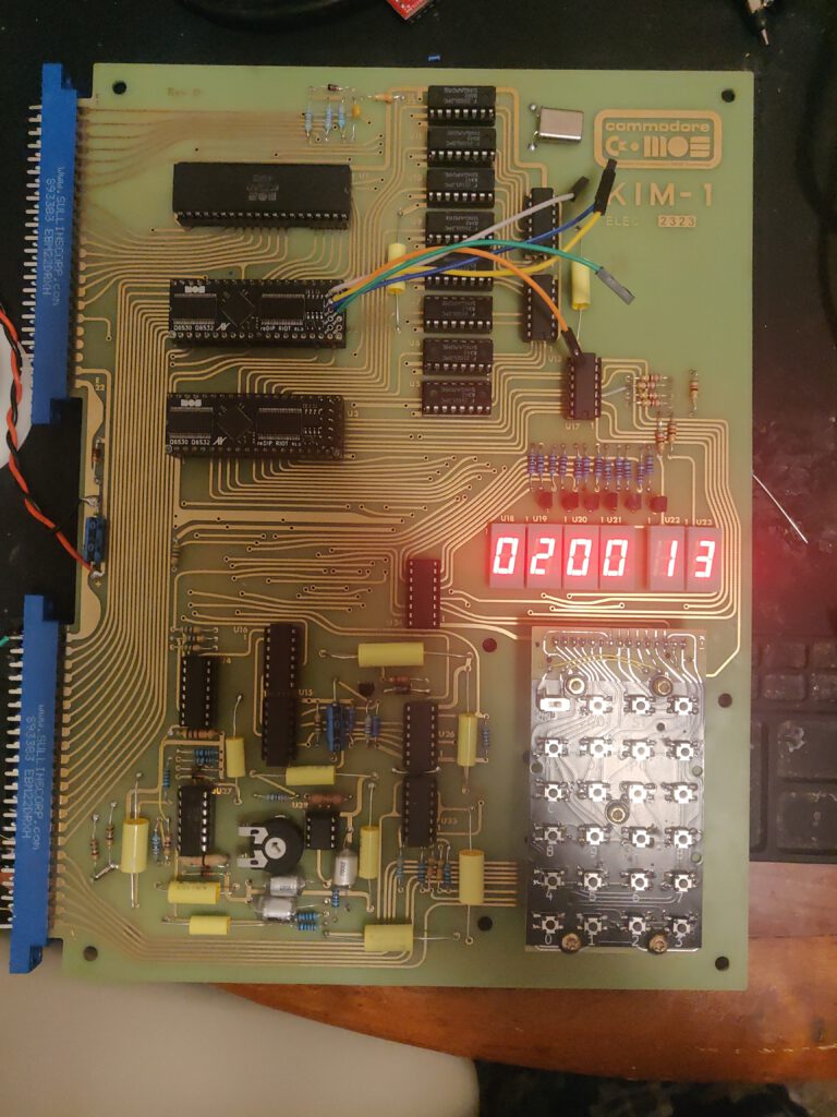
Since the 6532 is in fact a subset of the 6530 (no ROM, more RAM), it seems not too difficult to make a 6532 replacement this way.
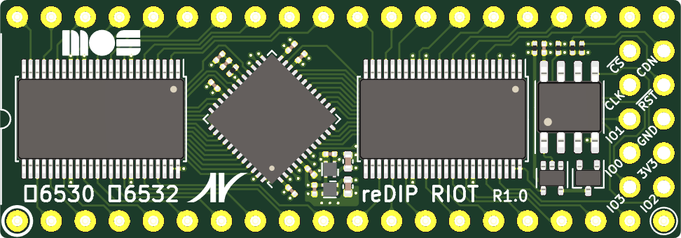
The reDIP RIOT is an open source FPGA board which combines the following in a DIP-40 size package:
Lattice iCE40UP5K FPGA
1Mbit FLASH
5V tolerant I/O
The reDIP RIOT provides an open source hardware platform for 6530 RRIOT / MOS 6532 RIOT replacements.
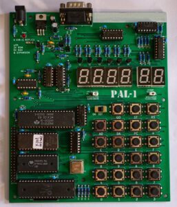
4 february 2025 2025 I have built the PAl-2 kit, now designing and building a I/O card.
This information is based upon the available documentation: User manual, Schematic, BOM.
The PAL-2 is for sale by Liu Ganning at Tindie
Just followed the interactive BOM, passive components first, ICs last.
Nothing special to note, compare yours with the photo on the PAL-2 Tindie site.
Orientation of IC sockets and IC’s, check twice!
Check your soldering joints, not too much sodler, but covered with the right color solder.
And the three slider switches,: the SST keyboard one has a higher slider that the other two!
Please be careful with the Dupont power cables, double check the polarity! If in error: magic smoke!
I do not like the Dupont wires for power, serial, TTY switch. Too easy to make a mistake in the power connection.
I am now designing and building a simple I/O card for the Application connector, experimenters print, point to point wires, male pin connector to PAL-2, on board female connector for USB to Serial, power switch, TTY/Keypad switch.
That may grow later to SD or 1541 or Corsham SD card interfaces.
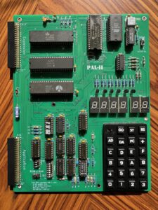
Video of PAl-2 #4, by Nils, running!
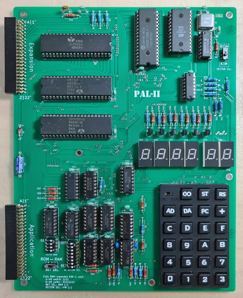
What is a PAL-2?
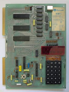
The PAL-2 is a kit for an SBC in the now large family of KIM-1 clones. Ranging from the Micro-KIM to the PCB exact replica by Eduardo Casino, all share the KIM-1 ROMs, LED display and TTY interface and the 6532 RIOT instead of the 6530 RRIOT.
What makes the PAL-2 unique:
It is a real and complete KIM-1 clone.
Available as a DIY kit with high quality components.
The layout is close to the KIM-1.
The good looking keypad is very close to the KIM-1
Application and Expansion connector with all relevant KIM-1 signals.
Lots of RAM in many configurable options.
Both RRIOTS 6532 on board.
TTY interface on TTL level, USB to TTL adapter included in the kit, quality serial!
Power can come from the USB to TTL adapter or from external 5V supply (same as for the KIM-1)
The PAL-2 differs from a KIM-1
No Audio cassette interface for file I/O circuit, but see below for a solution
Application and Expansion connector as 22×2 pinheader instead of PCB edge connectors
The signals on the Application connector are not all identical: no audio, TTY instead of 20 mA loop, decoding lines added
Not the same size PCB
The PAL-2 differs from the PAL-1:
The many quality improvements and enhancements make the base PAL-2 kit more expensive then a base PAL-1 kit.
If you expand the PAL-1 to the level of a PAL-2 you need to spend money on a motherboard, a RAM 32K, a second RRIOT kit, an RS232 cable and gender changer and a 9V power supply.
Improved keypad, with labels and look of the KIM-1
No need for a Motherboard
No external RAM module required
No external RRIOT required
E000-FFFF can be used freely from ROM expansion
The vectors (Reset, NMI, IRQ) can be placed in external ROM.
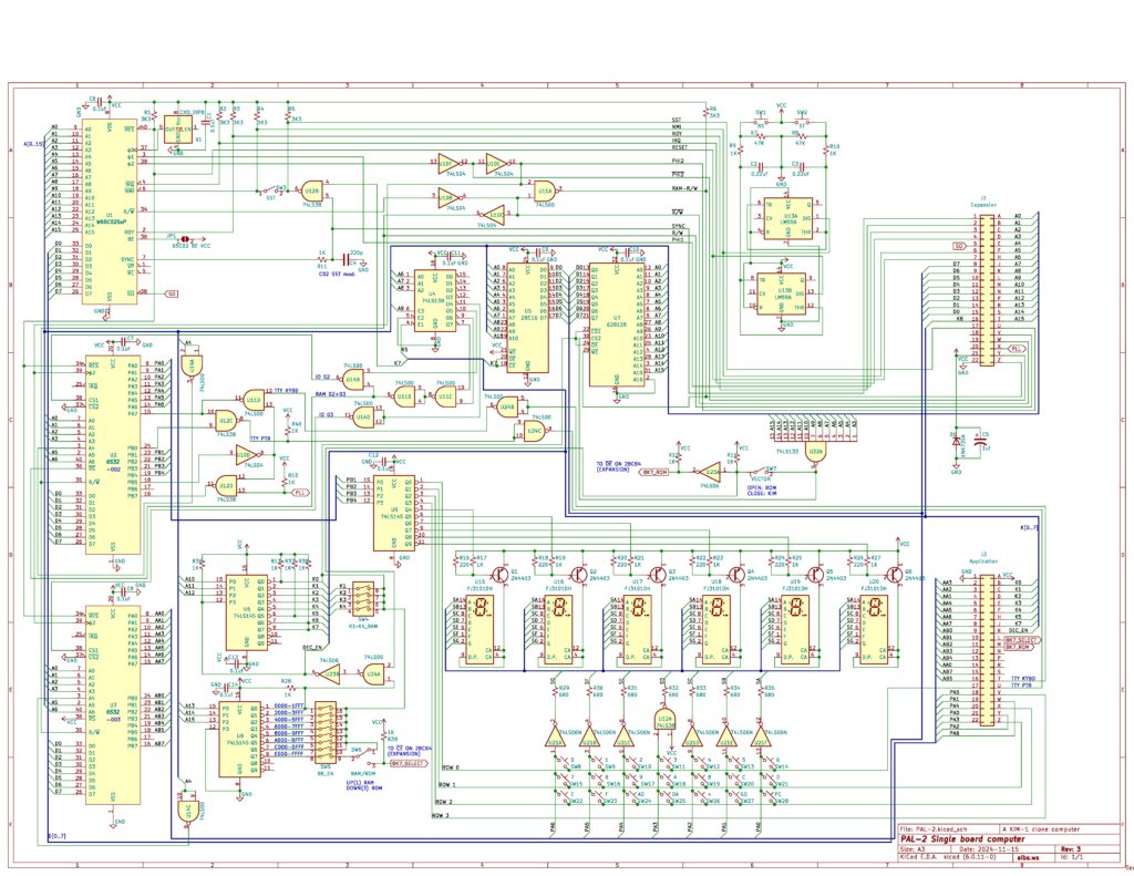
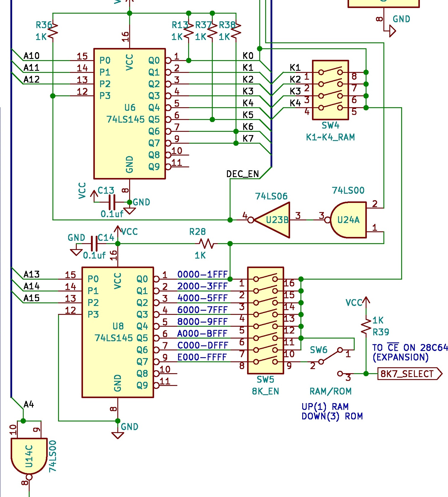
RAM decoding
The PAL-2 has a very flexible RAM memory layout, as shown in the next parts of the schematics:
Internal ROM and external ROM
The PAL-2 has a 2K ROM with the KIM-1 monitor. Since there is no audio in and out circuitry, the ROM from 1800-1BFF could be used for other programs, like the KIM Clone by Corsham Technology (Which also did not have the audio circuitry). The 28C16 is easy to program.
One of the first expansions that is to be expected is an external 8K ROM. The decoding for this ROM, e.g. an 28C64 is already present on the connectors and in the decoding circuit.
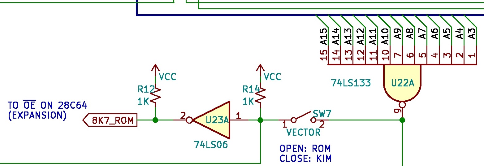
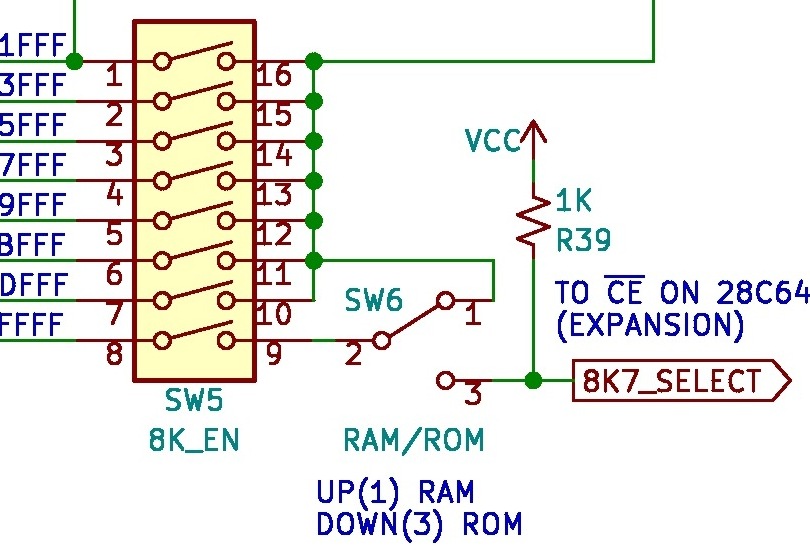
The decoding signals are 8K7_SELECT (CE on 28C64) and 8K7_ROM (OE on 28C64). Just the 28C64 IC has to be connected to address and data lines.
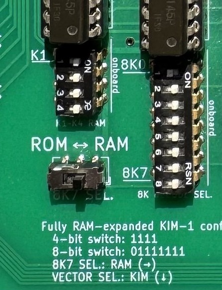
DIP Switches
The PAL-2 has a full 64K address decoder onboard, while the KIM-1 has only a 5K onboard address decoder for expansion. These two DIP switches on the PAL-2 are designed both to expand the KIM-1’s RAM and to maintain compatibility with its basic configuration.
On the PAL-2, the 4-bit DIP switch enables the onboard K1 to K4 RAM spaces, with each bit controlling 1K of memory. The K1 to K4 naming follows the definitions in the KIM-1 user manual, covering the address range from $0400 to $13FF. If all four DIP switches are set to ON, the entire 5K RAM space becomes available to the system.
The 8-bit DIP switch controls the “big segment decoder,” with each bit corresponding to an 8K memory block. These blocks range from 8K0 to 8K7, with 8K0 ($0000 to $1FFF) being the KIM-1’s default occupied address space. Since the PAL-2 is a KIM-1 replica, if you want to use it as a KIM-1 system, 8K0 must be set to OFF to allow the onboard KIM-1 logic to function. However, if you’re building a completely new system on the PAL-2, you can set 8K0 to ON to bypass the KIM-1’s onboard logic for the lowest 8K of memory.
The 8K1 block starts at $2000, controlling an 8K space beyond this address, and so on. If a bit is set to ON, the KIM-1 system will be able to access the corresponding address space, which will function as RAM. If a bit is set to OFF, the KIM-1 system will still work, but with reduced available address space. When performing expansion or add-on modifications on the PAL-2, you may need to disable certain address spaces to prevent the onboard logic from accessing the RAM chip.
The 8K7 block, representing the highest 8K memory segment, offers additional flexibility on the PAL-2. If 8K7 is set to ON, you can choose how to use this space—either as RAM or ROM—by adjusting the 8K7 SEL switch. For example, if you write a program (such as a tiny OS for the KIM-1) and burn it onto a ROM chip—similar to the well-known Jim’s ROM (but smaller)—you can connect the ROM to the PAL-2 (with some additional hardware, which is still under development). To boot from your ROM chip, use the VECTOR SEL switch to select ROM, allowing the system to retrieve the top three vectors from the ROM chip instead of the onboard KIM-1 ROM.
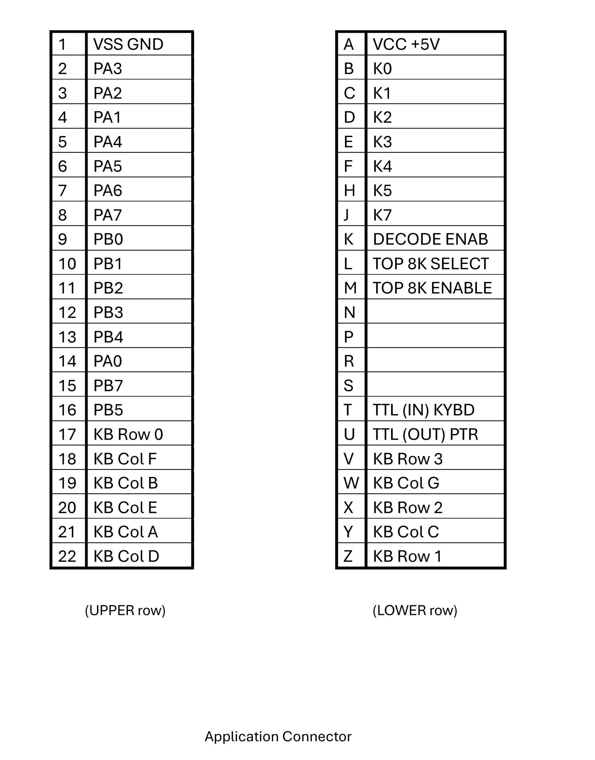
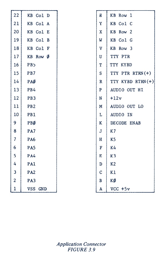
Application and Expansion connectors
KIM-1 Application connector
Differences on the Application connector with the KIM-1:
AUDIO IN -> 8k7_SELECT
AUDIO OUT LO -> 8K7-ROM
TTY in and out now at TTL level for USB to TTL converter
TTY PTR and KYBD, +1wV, AUDIO OUT LO not connected
This means, even if the edge to pin connector issue is solved, the standard KIM-1 I/O boards will not work for TTY and audio.
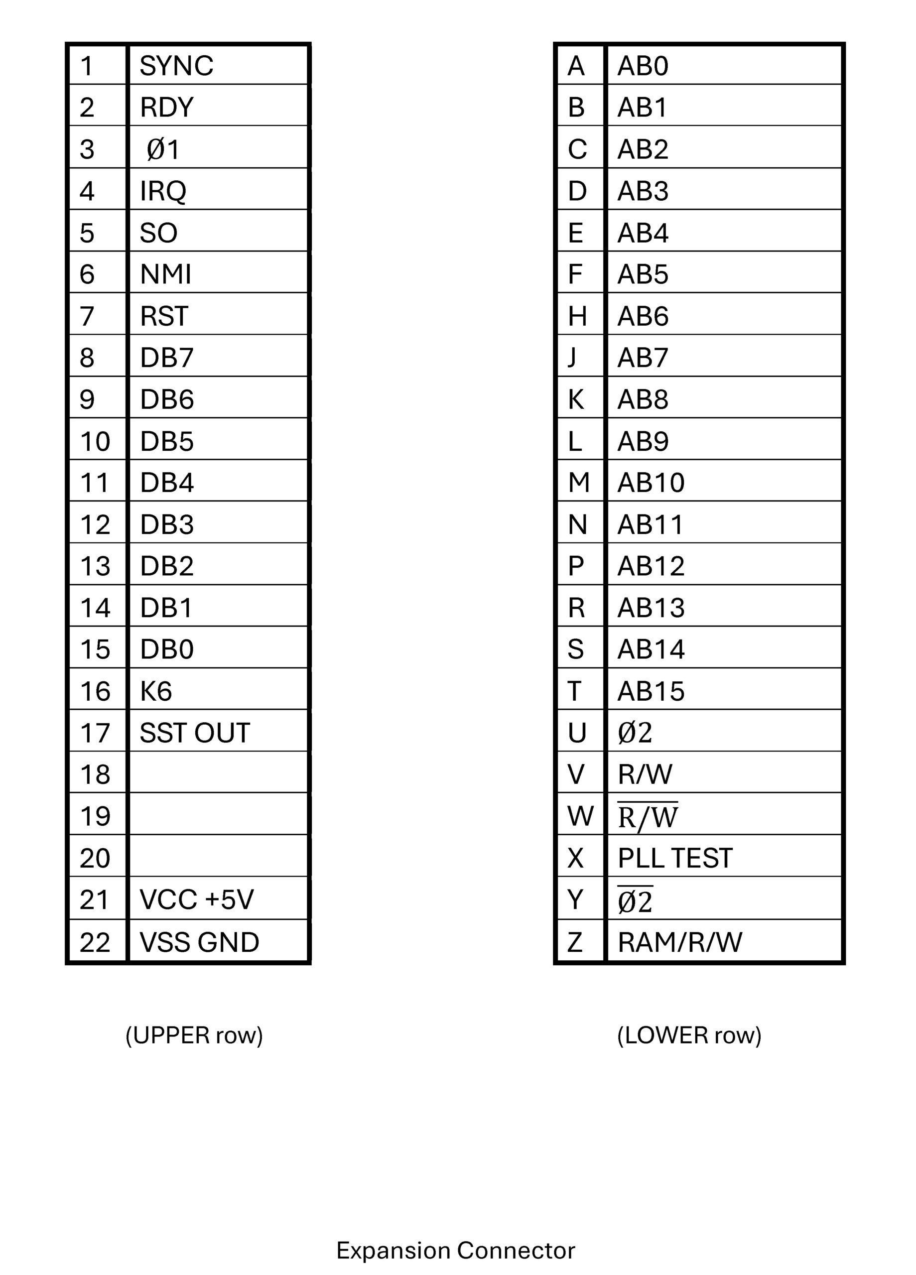
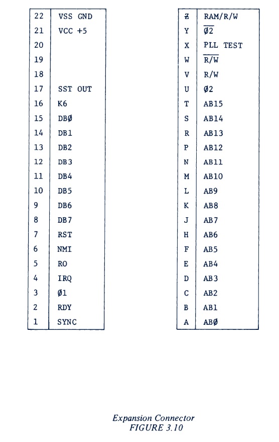
The expansion connector is identical to the KIM-1.
KIM-1 Expansion connector
Power supply
Power has to be applied in the standard KIM-1 manner to the application connector Pin 1 = GND, pin A = 5V. Note that reversing these pins will mean the dead of the PAL-2!
Expansion
As a first suggestion for a PAL-2 extension I see a board connected to Application and Extension connectors with:
Power switch
28C64 (or bigger, switchable in 8K chunks) EEPROM
Connector for the USB to TTL
External power connector, switchable between this and USB to TTL connector
TTY/LED keyboard switch
connector for the Application I/O ports PA0-PB7
Power switch
Optional:
Pin connector for PAL-1 Cassette Interface audio board
The KIM-1 has hardware and software in the 6530-003 ROM to save and dump files on audio tape.
Not used by most KIM clone users, so it is not present on the Corsham KIM Clone and the PAL-2.
But it is possible to have the audio in/out with one patch wire between pin 11 of U12D and the application connector!
KIM-1 Audio and TTY circuit
PAL-2 Audio and TTY circuit
On the KIM-1 circuit you can see the audio I/O is seen by the CPU at pin PB7 of the 6530-003. It is either an input or an output under control of the audio routines in the ROM.
The U26 (also present on the PAL-2 as U12d) is an open collector NAND feding PB7. On one input of U26 is PB5 from the 6530/32 (inverted by U16 (KIM-1_ or U10D (PAL-2), on the other is the output of the audio circuit generating TTL pulses from the audio sound input. This way PB7can be used both as input and output.
The PAL-2 and the KIM-1 has on the extension connector the signal PLL(_TEST), which is connected to U126/U12D. This is on the KIM-1 the output of the audio circuit.
So we have audio in (at TTL level) on the PAL-2 covered!
Audio out is available at PB7 at TTL level. With a patch wire between PB7 (or pin 11 of the U12D) to the application connector.
With the PAL-1 Cassette interface we can have the PAL-2 read and write KIM-1 audio cassette files this way. PLL_TEST to TAPE and a wire from PB7 to PB7 is all you need to connect to the Cassette Interface (and GND and +5V ofcourse).
Leaving R9 out of the Cassette Interface may be a good idea, there is already a pullup in the PAL-2 of 1K.
Physical Dimensions
The connector on the PAL-2 is a 2.54 mm pitch 2×22 female pin header connector.
The dimensions of the PAL-2 PCB are 168 mm x 218 mm.
Next two images show the connector, first shows the distance between the two connectors, while the second shows the distance from the PCB edge to the connector’s outer side.
Where is KIM Going?
Richard Simpson, KIM Forum, Kilobaud 1977
One of the questions most frequently asked me was “what are the future plans for KIM?” Most KIM owners are aware that MOS offers a KIM-2 4K RAM expansion board and a KIM-3 8K RAM expansion board. Either of these can be attached directly to a KIM-1. To expand further, a motherboard (KIM-4) must be added and MOS has planned a KIM-5 ROM expansion board, which will hold up to eight MCS6504 (2K by 8) mask-programmed ROMs (the ROMs are not provided with the KIM-5 but must be purchased separately). At present, there are two sets of software which are planned for release in ROMs – KIMath and a resident assembler/editor.
KIMath
KIMath will occupy a single ROM and consists of a set of subroutines for doing floating-point arithmetic. All calculations are done in BCD to avoid the round-off errors which are inherent in binary floatingpoint routines. The subroutine user can specify the precision (in decimal digits) of any calculation. The more precision specified, of course, the longer the computation time. The package will handle a maximum of sixteen decimal digits of precision plus a two digit exponent so numbers in the range of ±1 times 10E±98 can be handled. The subroutines occupy memory locations F800-FFF8 and were written so they could be used with any 650Xbased system – not just KIM. The subroutines include code for addition, subtraction, multiplication, division, square roots, logs, exponents, tangents and arctangents. All the other trig functions can be generated through the use of trigonometric identities. A subroutine is also provided for evaluating user-specified polynomials, so any continuous function can be approximated.The KIMath ROM should be available by the time you read this. If you don’t want to pay $50 for the ROM, the Programming Manual for KIMath is available for $15 and it includes a complete listing of both source and object code. The manual also contains thirtyseven pages of information on using the subroutines, including a worked-out sample application. If you want to use the ROM but balk at paying $80 for the KIM-5 board to hold it, you’ll be happy to know that the 6540 ROM can be attached directly to the KIM address and data busses, although you’ll need a couple of extra ICs to send the right signal to the KIM-1 Decode Enable line. I’ll provide an interface schematic for this in a future issue of the KIM forum.
The Resident Assembler /Editor
To create any large-scale software on a microcomputer, an assembler is a necessity. Industrial microcomputer users can use the crossassemblers available on several commercial timesharing systems, but the expense of going this route is too much for any but the most affluent hobbyist. Thus, the introduction of the KIM resident assembler should facilitate user software generation and make a lot more software available. The assembler and text editor are available as a set of three MCS6540 ROMs – a total of 6K of code. The $150 which MOS charges for the set may seem exorbitant until you realize that you don’t have to buy 6K of RAM to store it in (which would cost as much or more) and you’ll never have to load it or have it clobbered by errant statements in the program you are developing. Like KIMath, the Assembler/ Editor will work on any 650X-based system. Since the program has to do terminal I/O, locations are reserved in memory page zero to contain the address of the terminal input and output routines. These locations are automatically initialized for KIM owners; users of other 6500 systems (JOLT, TIM, Apple, Baby!, OSI, etc.) can preset those locations with the addresses for the device service routines of their own system. The Editor/Assembler occupies the memory space from E000 to F7FF; thus the editor, assembler, and KIMath fit together in the top 8K of memory.The text editor is a standard line-numbered text editor; it provides much the same editing capability you would find in a BASIC system. You can enter or insert new lines, replace old lines, resequence the line numbers, dump the text file to audio cassette or paper tape, list out lines in the file, and locate lines in the file which contain any specified text string. There is also a special command (actually, any command which begins with an X) to allow you to jump to a user-written subroutine so that you can extend the editor’s capabilities to meet your own needs. Naturally, both the editor and assembler require that you have a terminal connected to the serial port on the KIM-1.The assembler is a singlepass assembler; if your source text is on paper tape or audio cassette, you only have to feed it through once. Normally your source text will be in memory and the assembled code is always written to memory. The source code, symbol table, and object code can be located anywhere in memory you wish. You may have several different source files in memory simultaneously. If you have insufficient memory space to store a large source program, you can break it into several segments, store each segment on audio tape, then bring back one segment at a time for assembly. The assembler will assemble the successive segments until it encounters an “END” statement. It will then put out the symbol table and terminate assembly. Although the editor is fairly limited (it has no capability to edit within a given line, for instance) it is quite sufficient for editing assembly language programs. The assembler is very fast and with good error diagnostics. Perhaps its only serious fault is that the printed symbol table is not sorted alphabetically and no crossreferences are given.
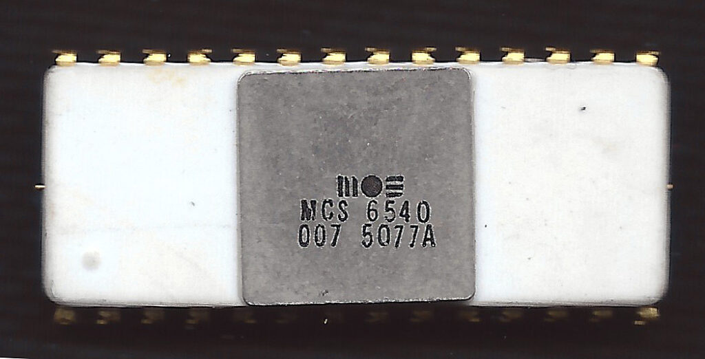
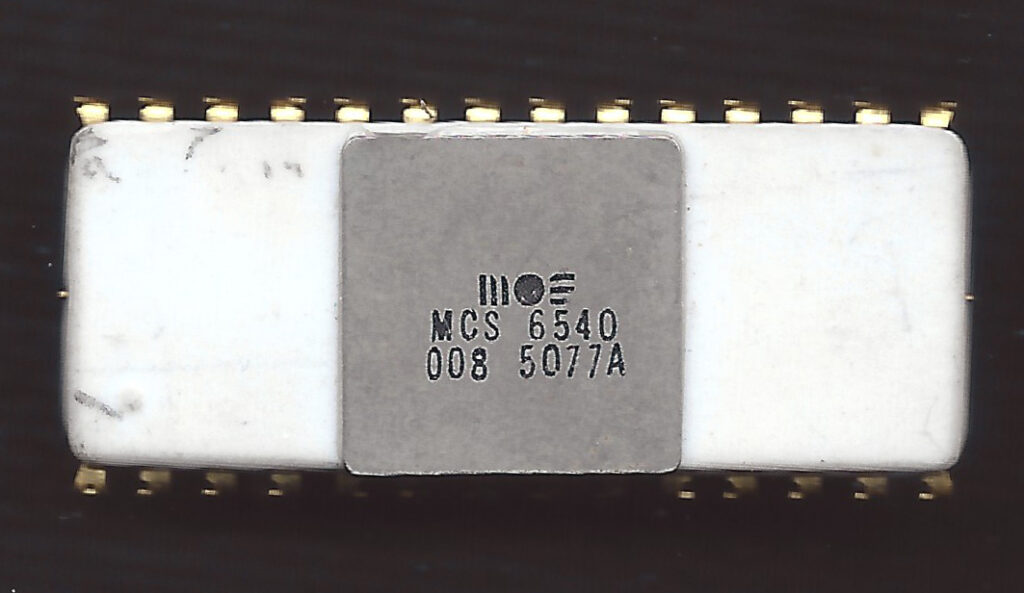
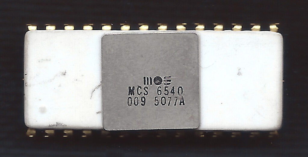
MOS 6540 ROM
The MOS Technology 6540 is a 16k (2KByte) ROM. Factory burned. Mask options for specification of chip select equations. 5! chip selects, requires Phi2 6502 system clock. 24 pin, very uncommon for a small ROM.
A strange and uncommon device, AFAIK only used in the KIM-5 Resident Assembler/Editor and early PET computers. Has a bad reputation, and there are many replacement solutions with standard E(E)PROMs for PET computers.
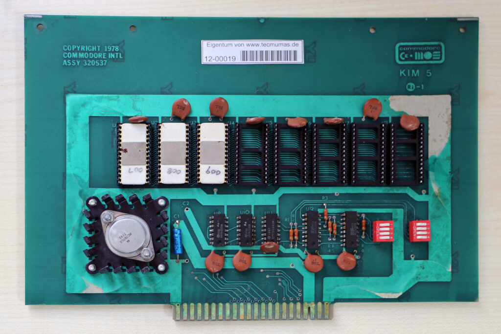
The 6540’s in the KIM-5 Resident Assembler/Editor on a KIM-5 ROM board are in an excellent condition, dumping with the Backbit Pro chip tester was very easy.
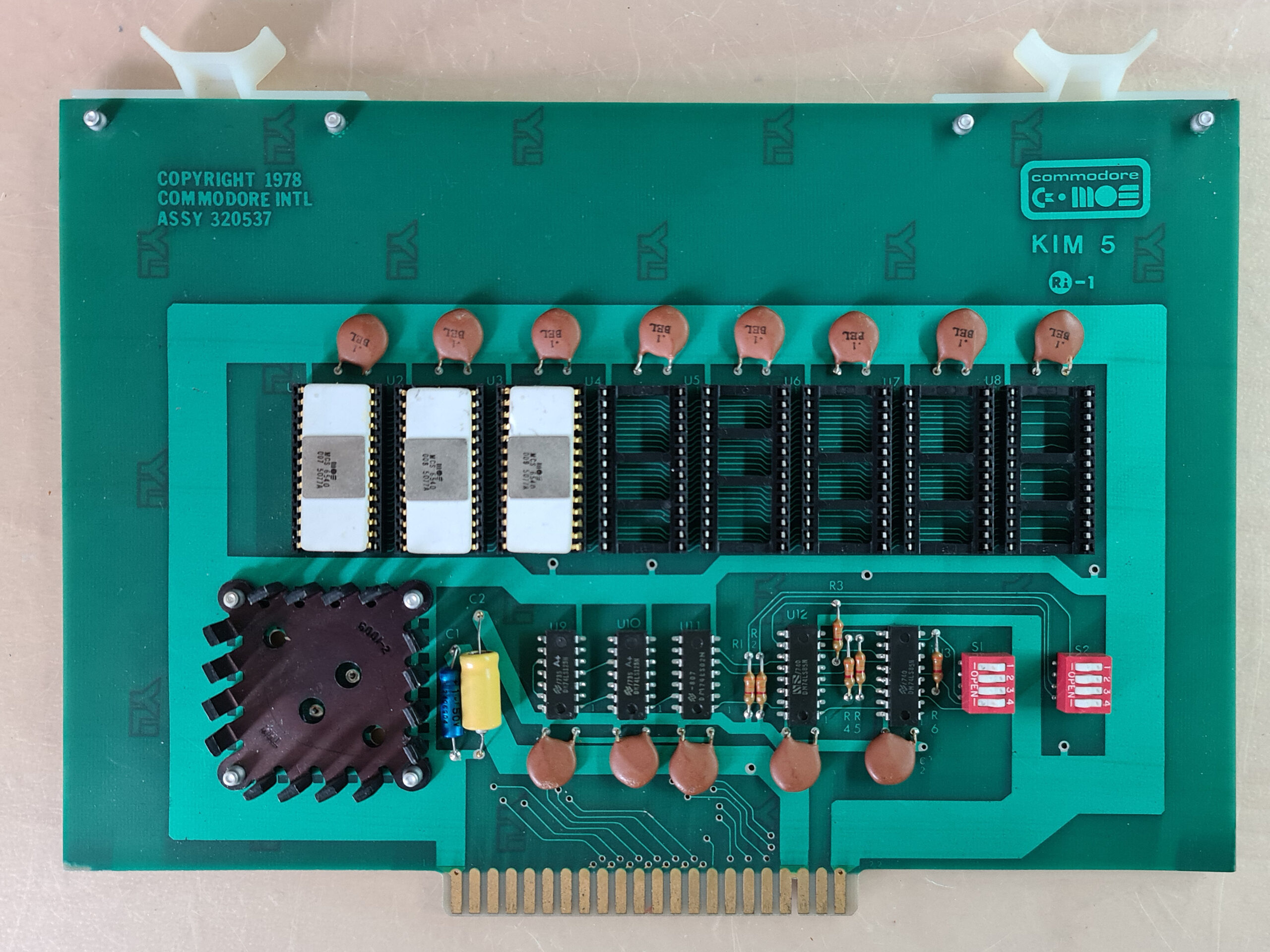
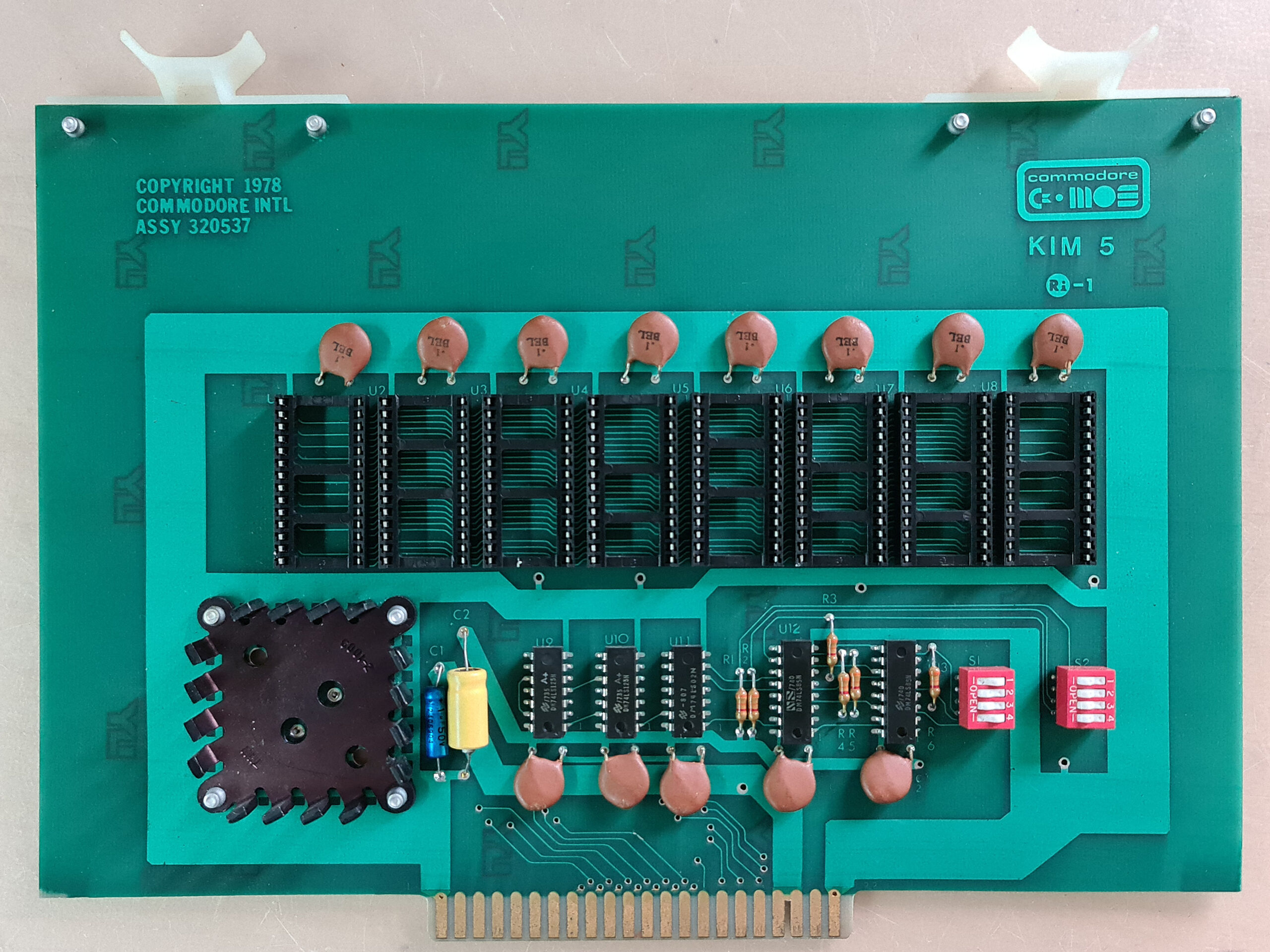
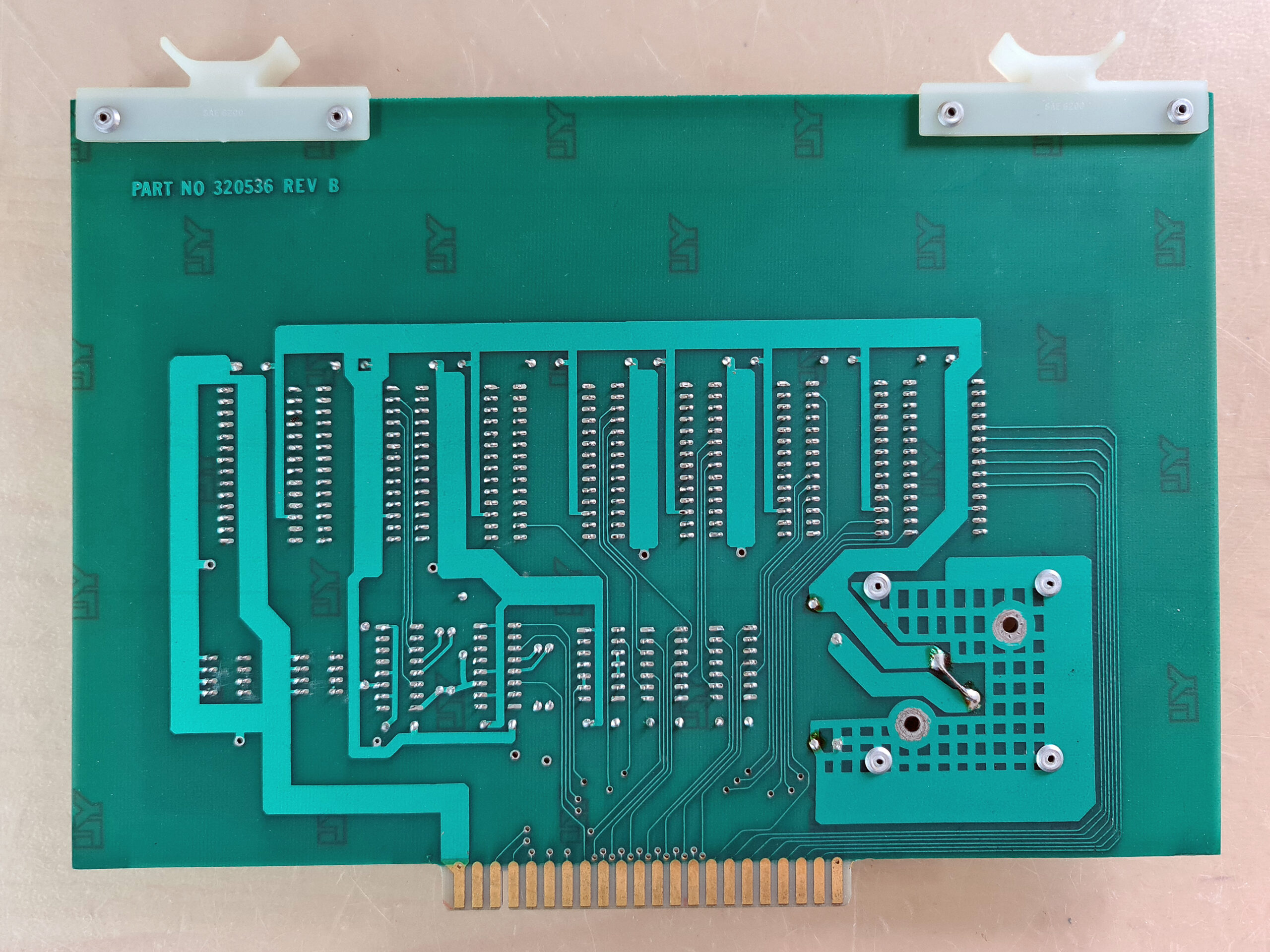
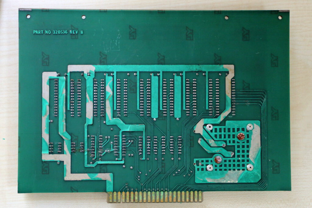
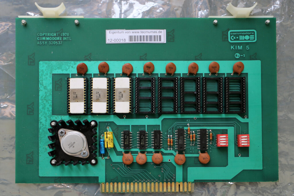
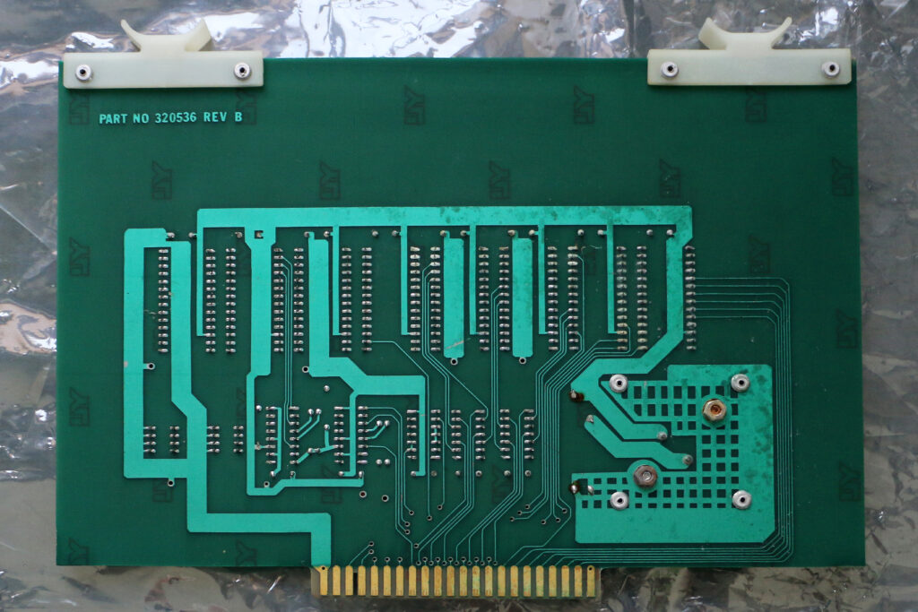
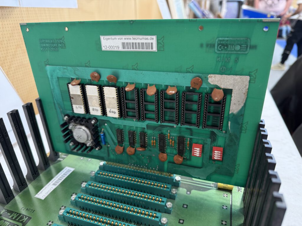
KIM-5 ROM board
The 3 KIM-5 Resident Assembler/Editor ROMs as placed on the KIM-5 ROM board.
Besides the sockets for the ROMs is some glue logic, 2x 74125 buffers, 2x 7485 address decoders, a 7402 TTL IC and some DIP switches.
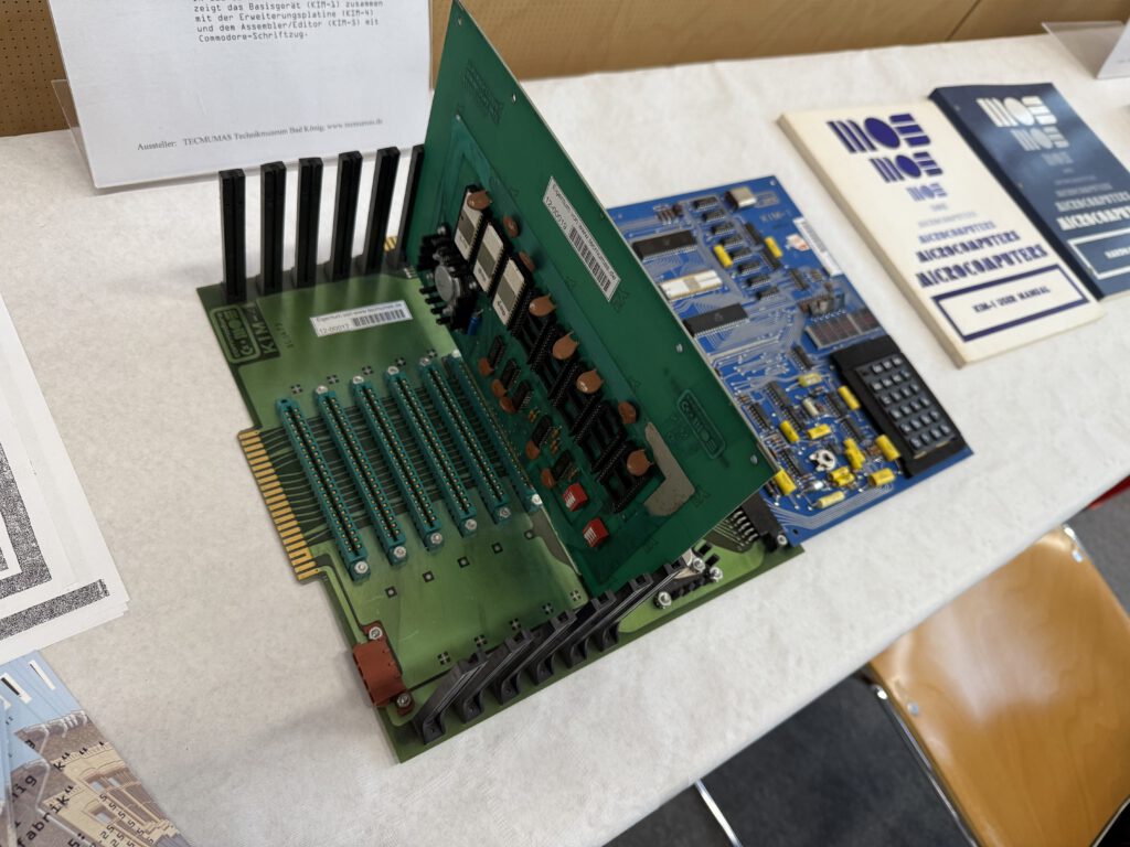
The KIM-5 ROM board is to be placed in the KIM-4 Motherboard. The manual is not available alas.
MOS Technology, part of Commodore in 1977, not only sold the KIM-1 SBC but added hardware and software as KIM System Products.
Not only hardware, a Motherboard (KIM-4), RAM memory expansions (KIM2, -3, -3B) and a prototype board (KIM-6) but also software, like KIM Math subroutines (KIMath), TIM (RRIOT + document).
This has been documented for quite some time now on this website with photos and manuals.
I have been looking for years for the KIM-5 Resident Assembler/Editor. Manuals on Assembler and Editor are already known. The software, delivered in 3 ROMs of type 6540, on a KIM-5 ROM board was never dumped before, and the existence, besides the pricelist shown here and some advertisements, doubted by many, including old Commodore employees.
Many years I searched on the internet on fora, websites and friends in the retro world, it did not lead to a dump of the KIM-5 ROMs.
A couple of years ago I saw a listing on ebay.de of a lot with a a KIM-5 with ROMs and a KIM-3B board. I was too late to bid. I could not contact the seller or buyer afterwards. But now I knew the KIM-5 did exist, and had some photos as proof.
A year later Stefan Hamann approached me to ask for information on KIM-1 material he bought from ebay. He was the buyer of the lot!
Stefan was so nice to lent me the KIM-5 (and KIM-3B) and the EPROMs he obtained. I have finally a KIM-5 in my hands with ROMs!
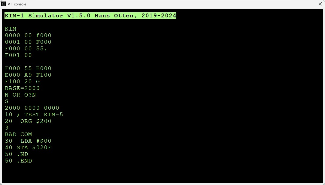
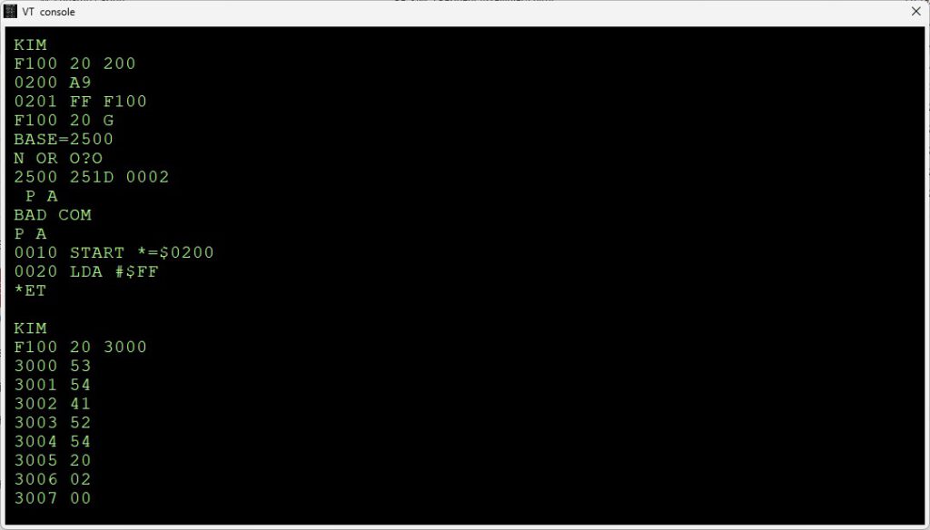
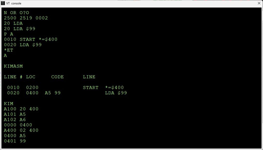
The ROMS have been dumped, tested in the (updated KIM-1 Simulator to 1.5.1) and source recreated. The KIM-5 Resident Assembler/Editor is preserved!