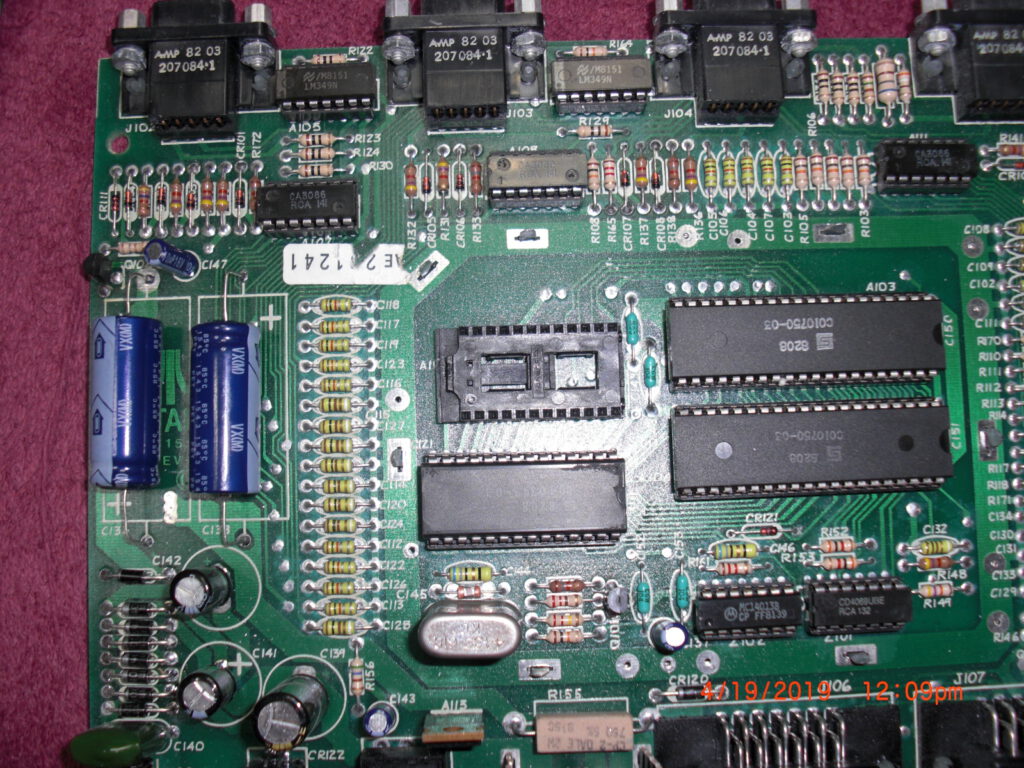
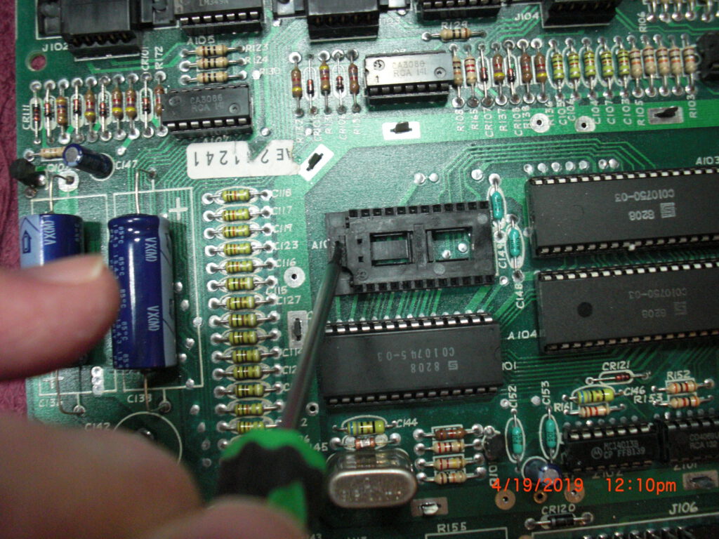
A 6507 CPU with a 6532 RIOT and a 27C512 EEPROM on a small breadboard.
Github with circuit diagram and sources
About small SBC systems
A 6507 CPU with a 6532 RIOT and a 27C512 EEPROM on a small breadboard.
Github with circuit diagram and sources
A Spanish firm developed a 6502 trainer, an SBC inspired by the KIM-1. Hexadecimal keyboard, 6 LED displays, I/O to experiment with. Assembled system, boxed, high quality components like mechanical keys. Aimed at education.
On this page:
All three share the same monitor program, patched for the MI-650C to use the 6522.
Statement by Promax about the 1979 Educational trainers
Educational instruments division was the result of our close commercial relationships with universities and technical schools. Work here was closely tied to the study plans of universities and technical schools in order to provide the educational material required by a variety of disciplines. Design work was begun on the MI-650B Microprocessor Trainer, based on the 6502 which appeared in 1975.
Updates from various sources, motivated by the find of Jose Vicente Marques Vidal of four MI-650s and our attempt to make them operational again (missing EPROMS mostly).
![]() |
PROMAX MI 650 μ-instructor |
![]() |
PROMAX MI-650-C Microinstructor (contains ROM listing and more) |
![]() |
Microprocesadores de 8 bits 6502 promax MI-650C microinstructor |
EPROM images are supplied by John Evans (in the KIM-1 Facebook group) and Youtube user @eeep73 and Dominic Bumbaca.
Identical dumps from two different MI-650s, so good dumps!
Archive with Promax MI-650 EPROM images (2x 2716 EPROMs).
Photo by Dominic Bumbaca
Archive with Promax MI-650 monitor source
Archive with Promax MI-650C monitor source
Videos of MI-650 demonstrations
https://www.youtube.com/watch?v=PypHSDdsIX
KIM-1, AIM-65, SYM-1 and other 6502/65C02/65C816 related books.
A mix of English, German and Dutch books.
On my bookshelf I have quite a collection of books on the 6502 family.
Note that manuals and books that come with systems are shown on the pages of the corresponding system!
The Chessmate is a 6530 – KIM-1 like computer. Keyboard, LED display are used as in the KIM-1. Peter Jennings, who designed this chess computer with Commodore, build upon his Microchess 1. from the KIM-1, and used the extra ROM space to enhance it to Microchess 1.5: more chess features, a chess clock, sounds, dedicated keys, status LEDs.
The 6530-024 delivers the I/O and timer and RAM used by the Chessmate, the RRIOT ROM is not used by the main ROM. The dumped ROM of the 6530 (see below) contains no recognizable data or program,
It will not be that difficult to ‘clone’ this chess computer with the information here. A 6532 can easily take the role of the 6530. A 6502 instead of a 6504, same SRAM< a 2732 or similar ROM. The ROMs are dumped, both for an Chessmate and a Novag Chess Champion MK I
Schematic, user manual, dumped ROMs here. My Chessmate
Though this site is not about home computer systems, but about small SBC’s, it is nevertheless interesting to look at the Atari 850 system.
Atari produced the 850 Interface Module to provide access to devices complying with two important interface standards of the time, RS-232-C serial and Centronics parallel.
Four serial interfaces, one parallel interface in self contained case, with its own power supply. Connected to the Atari via the standard SIO cable.
When you look into the system you discover it is actually a simple microprocessor system. The heart is a 6507 CPU, the serial and parallel lines are built with two 6532 IC’s, a ROM with the software.Serial interfaces and the 6532? This means bit banging.So this fits well in the theme of small SBCs!
Though this site is not about home computer systems, but about small SBC’s, it is nevertheless interesting to look at the Atari 850 system.
Atari produced the 850 Interface Module to provide access to devices complying with two important interface standards of the time, RS-232-C serial and Centronics parallel.
Four serial interfaces, one parallel interface in self contained case, with its own power supply. Connected to the Atari via the standard SIO cable.
When you look into the system you discover it is actually a simple microprocessor system. The heart is a 6507 CPU, the serial and parallel lines are built with two 6532 IC’s, a ROM with the software.
Serial interfaces and the 6532? This means bit banging.
So this fits well in the theme of small SBCs!
I show you here the circuit diagram, operator, service and technical manual and the sources/binaries of the ROM.
While the Atari's SIO and controller ports did not conform to established industry standards, Atari produced the 850 Interface Module to provide access to devices complying with two important interface standards of the time, RS-232-C serial and Centronics parallel. RS-232-C Serial Interface ------------------------- The Electronic Industries Association (EIA) introduced the RS-232 standard, entitled "Interface Between Data Terminal Equipment (DTE) and Data Circuit- Terminating Equipment (DCE) Employing Serial Binary Data Interchange," in 1960 in an effort to standardize the interface between DTE (usually a terminal or a computer emulating a terminal) and DCE (usually a modem). Although emphasis then was placed on interfacing between a modem unit and DTE, other applications for the standard gained popularity. Early versions of the EIA 232 standard included RS-232 (1960), RS-232-A (1963), and RS-232-B (1965). From 1969-1987, including most of the time of the 8-bit Atari, the standard was formally known as EIA RS-232-C. Revisions since then have included EIA- 232-D (1987), EIA/TIA-232-E (1991), and the current version from the Telecommunications Industry Association, EIA/TIA-232-F (1997), known as of 2011 as TIA-232-F. Especially in the 1980s, 232 was widely adopted for low- cost serial connections between the DTE and peripherals such as an external modem, mouse, plotter, printer, scanner, digitizer, track ball, and myriad others. In more recent years TIA-232-F has essentially been supplanted by USB. In keeping with the context of the time period, this FAQ will normally refer to the 232 standard as RS-232-C. The Atari 850 interface connects to the SIO port on the Atari computer and provides the system with: - Four serial interface ports (RS-232-C) - One 8-bit parallel output interface port (Centronics) Serial interface port key features: - The 850 functions as RS-232-C Data Terminal Equipment (DTE). - RS-232-C Circuits (signaling lines): (Send / Out) | (Receive / In) Port 1: XMT, DTR, RTS | RCV, DSR, CTS, CRX Port 2: XMT, DTR | RCV, DSR Port 3: XMT, DTR | RCV, DSR Port 4: XMT | RCV - Port 4 primarily serves as a 20 mA current loop interface, supporting 20 mA current loop peripherals such as a teletype machine. - Baud rates: 45.5 bit/s*, 50 bit/s*, 56.875 bit/s*, 75 bit/s**, 110 bit/s, 134.5 bit/s, 150 bit/s, 300 bit/s, 600 bit/s, 1200 bit/s, 1800 bit/s, 2400 bit/s, 4800 bit/s, 9600 bit/s * These baud rates are useful for communications with Baudot teletypes, for RTTY (radioteletype) applications. They are more commonly referred to as 60, 67, and 75 words per minute. ** This baud rate is sometimes used for ASCII communications, and may also be used for 5-bit Baudot RTTY. The latter is commonly referred to as 100 words per minute. The Atari Operating System does not include a resident device handler for the serial ports of the 850, but the 850 contains an R: handler, supporting devices R1: through R4:, in its ROM. - Bootstrap without disk drive-- With no powered disk drive #1 present, the R: handler loads from the ROM of a powered 850 into computer RAM on system startup. (The 850 masquerades as disk drive #1, responding to the Atari OS attempt to boot from disk.) An extended beep is emitted through the computer's audio signal as the handler is loaded. - Bootstrap with disk drive-- The R: handler can be loaded from the 850 ROM as part of a Disk Boot. (Atari DOS 2.0S, DOS 3, DOS 2.5, and DOS XE include provisions for this.) - The R: handler can be loaded from the 850 ROM by software after system boot. Many alternatives to the 850 ROM R: handler have been developed. Please see a separate section of this FAQ list regarding R: and T: device handlers for the 850 for more details. The Atari Operating System's resident P: Printer device handler supports the parallel output interface port of the 850. - 400/800 OS: Responds to P: and ignores any device number XL OS: Responds to P:, P1:, and P2: PINOUTS ======= Serial Interface Port 1 (DE-9 Socket - female): 1. DTR Data Terminal Ready (Out) 2. CRX Carrier Detect (In) 5 1 3. XMT Send Data (Out) o o o o o 4. RCV Receive Data (In) o o o o 5. Signal Ground 9 6 6. DSR Data Set Ready (In) 7. RTS Request to Send (Out) 8. CTS Clear to Send (In) Serial Interface Port 2 (DE-9 Socket - female): 5 1 1. DTR Data Terminal Ready (Out) o o o o o 3. XMT Send Data (Out) o o o o 4. RCV Receive Data (In) 9 6 5. Signal Ground 6. DSR Data Set Ready (In) Serial Interface Port 3 (DE-9 Socket - female): 5 1 1. DTR Data Terminal Ready (Out) o o o o o 3. XMT Send Data (Out) o o o o 4. RCV Receive Data (In) 9 6 5. Signal Ground 6. DSR Data Set Ready (In) Serial Interface Port 4 (DE-9 Socket - female): / 20 mA Current Loop Operation 1. +10V / TXD+ Send Data + 5 1 3. XMT / TXD- Send Data - (Out) o o o o o 4. RCV Receive Data (In) --+ A 20 mA current loop o o o o 5. Ground | device must tie together 9 6 7. +10V / RXD+ Receive Data + --+ pins 4 and 7. 9. -8V / RXD- Receive Data - Parallel Interface Port (DA-15 Socket - female): 1. /Data Strobe 2. Data bit 0 3. Data bit 1 8 1 4. Data bit 2 o o o o o o o o 5. Data bit 3 o o o o o o o 6. Data bit 4 15 9 7. Data bit 5 8. Data bit 6 9. Data Pins Pull-Up (+5V)--+ A device that cannot hold 11. Signal Ground | /Fault high may instead tie 12. /Fault (high required)--+ together pins 12 and 9. 13. Busy 15. Data bit 7 Prototype 850 units are in an all-black brushed steel case, but production units are in a beige plastic case matching the 400/800 computers. Front of unit (left-to-right): - Power In jack - On power indicator light - Power Off / On switch - Two I/O Connectors (Atari SIO) Right side of unit: - Parallel Interface port Rear of unit (left-to-right): - Four Serial Interface ports, 4 - 3 - 2 - 1 850 internals: - 6507 MPU (MOS Technology MCS6507 or equivalent), C010745 - 6532 PIA. Two of: - MOS Technology 6532 RAM-I/O-Timer (RIOT) or equivalent, C010750 - 4KiB X 8 Bit ROM, C012099 Manuals: - Atari 850 Interface Module Operator's Manual C015953 Rev. 1 1980 (preliminary version shipped with earlier/most 850 units; 102 pages) - Atari 850 Interface Module Operator's Manual C017651 REV. B 1982 (15 pages) - Atari 850 Interface Module Technical Manual C017652 REV. B 1982 (106 pages) - Atari 850 Interface Module Field Service Manual - CS 400/800-S004-B 4/81 - FD100036 April, 1981 Power: Used with an external 9 volt AC transformer power supply rated for at least 17 watts: Atari CA014748 or equivalent. The 850 was designed by R. Scott Scheiman at Atari,
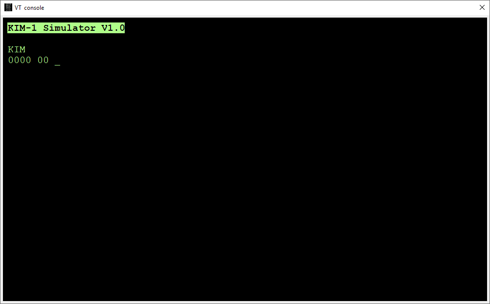
The base for all ‘modern’ KIM clones, KIM reproductions, MICRO KIM, PAL-1 and more.
Credits to Ruud Baltissen for the idea and details. ‘I’ means Ruud in this page!
RRIOTs are mask programmed for address selection, choices are:
Pin 18 PB6 or CS1
Pin 19 PB5 or CS2
Pin 17 PB7 can have a pullup
ROM selection on RS0, CS1 und CS2 s
RAM on RS0, CS1, CS2, A9, A8, A7 and A6
I/O on RS0, CS1, CS2, A9, A8, A7 and A6
See the various 6530/6532 datasheets for (some) more detail.
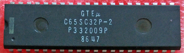
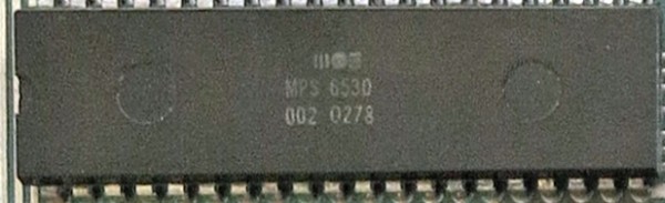
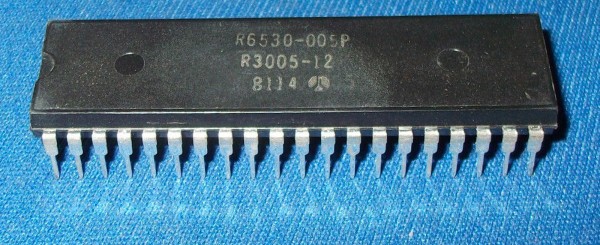
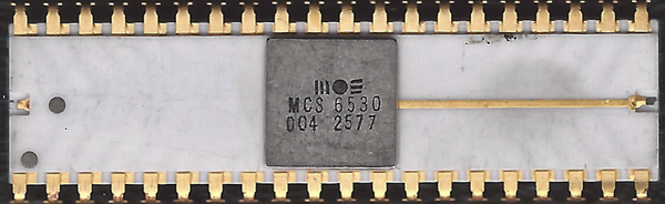
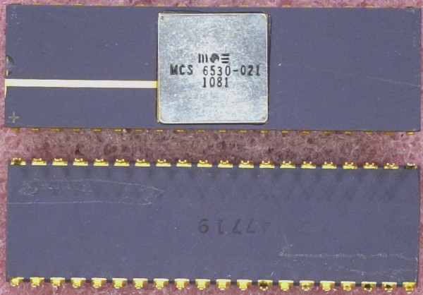
The KIM-1 has two 6530s on board. For more info about this IC, please read the datasheet. Anybody who is a little bit familiar with the hardware market can tell you that you cannot buy the 6530 anymore. Happily enough there is another IC available which you could call its brother: the 6532. The 6532 has 16 I/O-lines, an internal timer and 128 bytes of RAM on board, but no ROM. The internal ROM of the 6530 can be selected independently from the I/O. So for this project we’ll use an external EPROM as replacement. The pin out of the 6532 is completely different but that should not be a problem.
The next difference is the fact that the 6532 has a separate IRQ and PB7 line. As we will see, the functionality of both lines is the same as with the 6530. To create the same circumstances we only have to connect them together.
The third difference is the availability of PB6 with a 6532. See it as a bonus as I haven’t found any reason how it could jeopardize our project.
The fourth difference is that it is possible to generate an interrupt depending on the behaviour of PA7. But this is an option, which is out of function by default after a reset.
The last and major difference however lays in the way the registers are selected:
function: RS: A6: A5: A4: A3: A2: A1: A0: R/W: RAM 0 x x x x x x x x DRA 1 x x x x 0 0 0 x A DDRA 1 x x x x 0 0 1 x B DRB 1 x x x x 0 1 0 x C DDRB 1 x x x x 0 1 1 x D PA7, IRQ off, neg edge 1 x x 0 x 1 0 0 0 F PA7, IRQ off, pos edge 1 x x 0 x 1 0 1 0 G PA7, IRQ on, neg edge 1 x x 0 x 1 1 0 0 H PA7, IRQ on, pos edge 1 x x 0 x 1 1 1 0 I read interrupt flag 1 x x x x 1 x 1 1 E read timer, IRQ off 1 x x x 0 1 x 0 1 J read timer, IRQ on 1 x x x 1 1 x 0 1 K Clock / 1, IRQ off 1 x x 1 0 1 0 0 0 L Clock / 8, IRQ off 1 x x 1 0 1 0 1 0 M Clock / 64, IRQ off 1 x x 1 0 1 1 0 0 N Clock / 1024, IRQ off 1 x x 1 0 1 1 1 0 O Clock / 1, IRQ on 1 x x 1 1 1 0 0 0 P Clock / 8, IRQ on 1 x x 1 1 1 0 1 0 R Clock / 64, IRQ on 1 x x 1 1 1 1 0 0 S Clock / 1024, IRQ on 1 x x 1 1 1 1 1 0 T In total 5 address lines are used, meaning 32 registers. But 11 of the 19 registers have one or more mirrors. Read: J E J E K E K E J E J E K E K E Write: F G H I F G H I L M N O P R S T R/W: A B C D A B C D A B C D A B C D
As we can see, the last 16 registers equal the 16 of the 6530 itself.
So now we have to develop some logic which will do the following:
Conclusion:
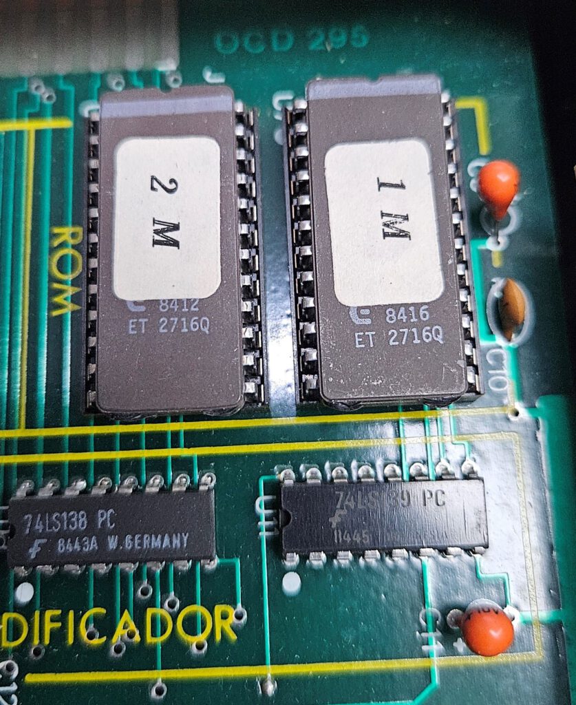
Here we have a luxury problem. We only need 2K of (EP)ROM like the 2716. The problem is that the 2716 is hard to find and more expansive then the 2764 or its bigger brothers. When we use a bigger EPROM we only have to tie the unused address lines to GND. The same problem occurs with the RAM.
If we have to use bigger RAMs or EPROMs anyway, it is quite easy to use other parts of that chip by OR-wiring the CS-line with more Kx-outputs of the main 74145. (Don’t forget the address lines!) In case of the EPROM we also can tie switches to the surplus address lines and have the advantage of a multi-KERNAL system.
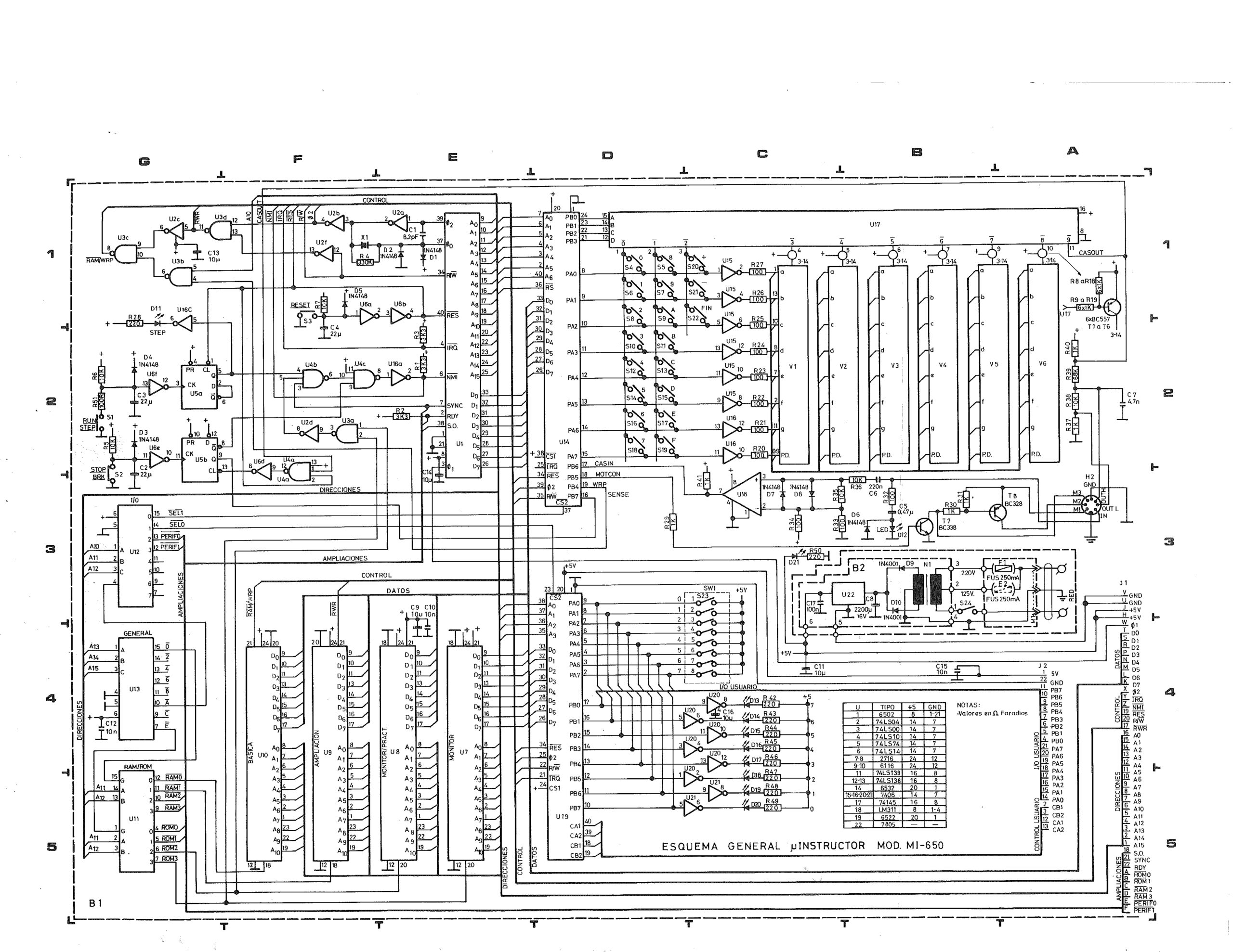
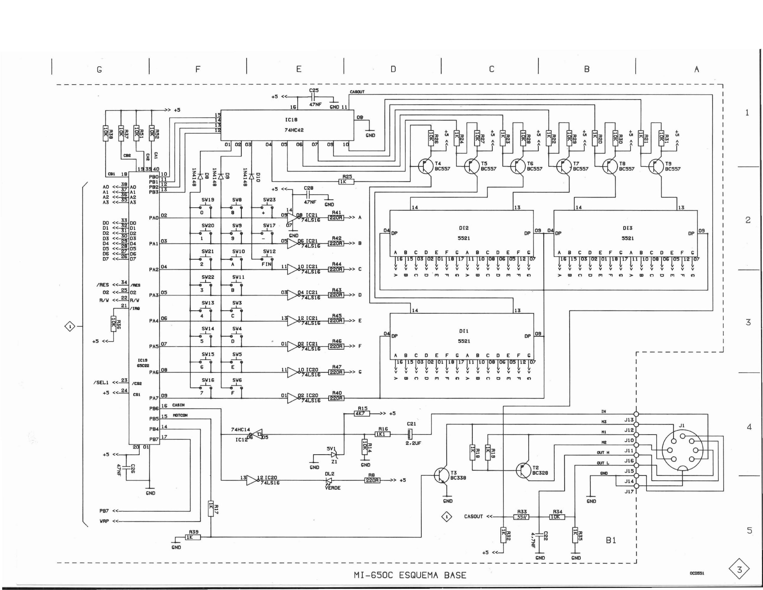
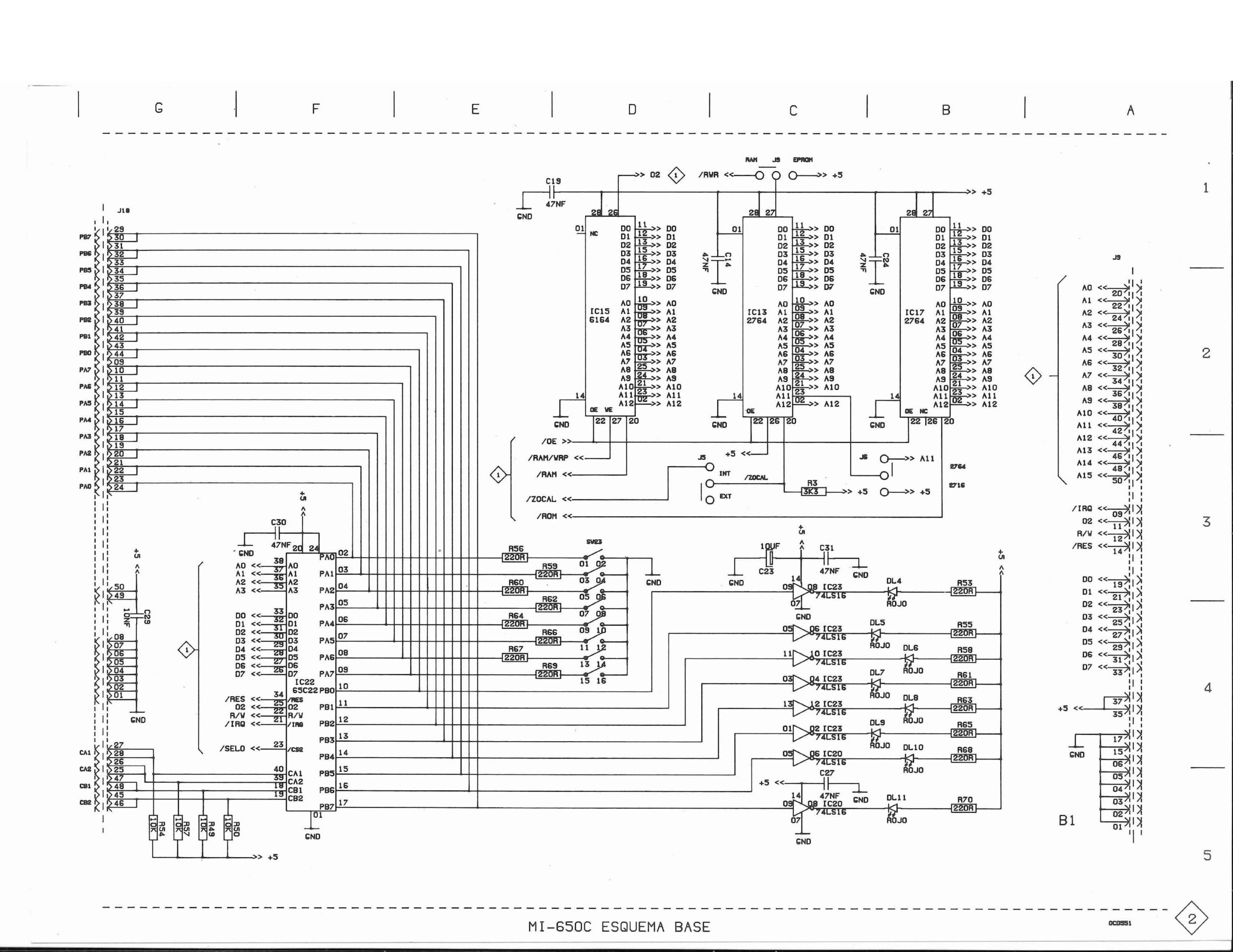
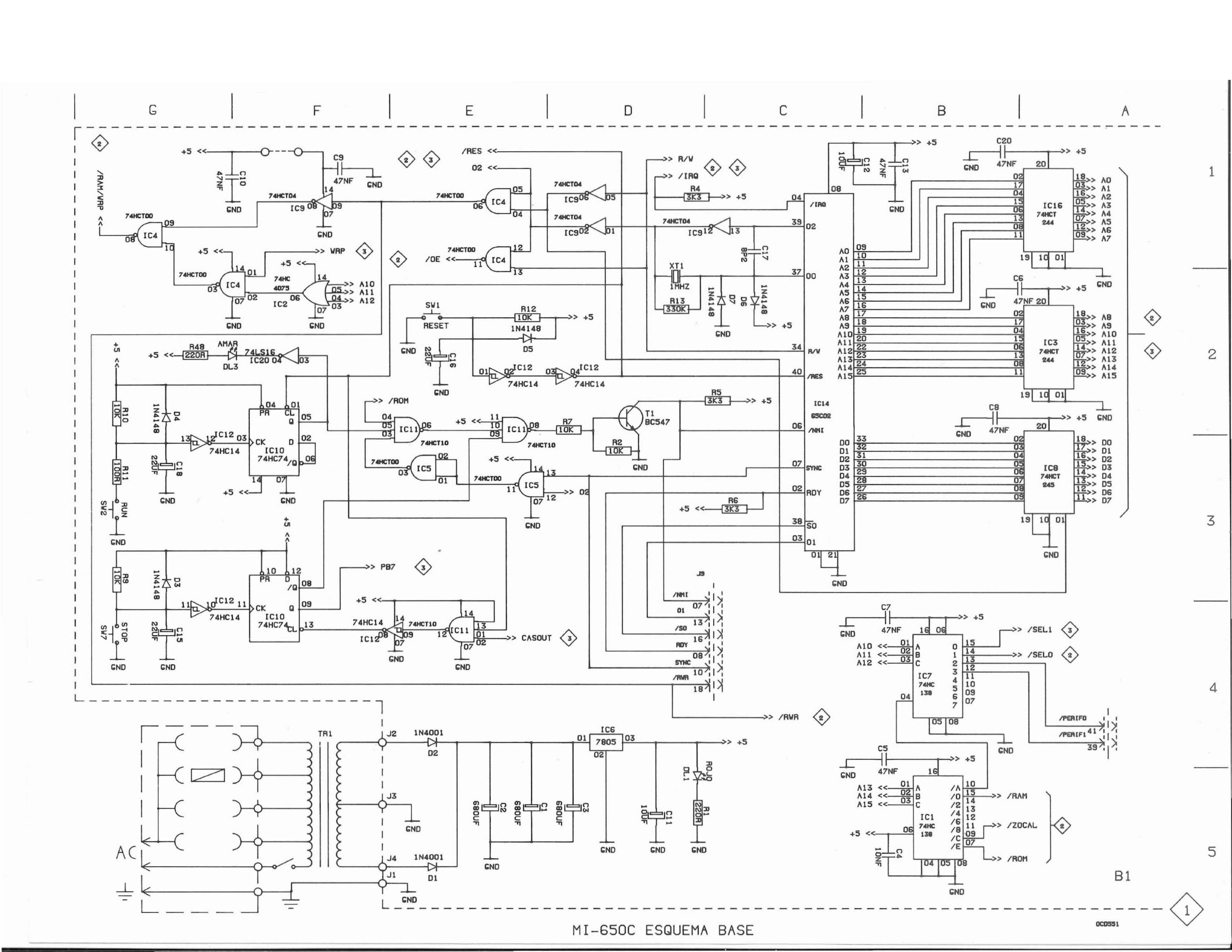
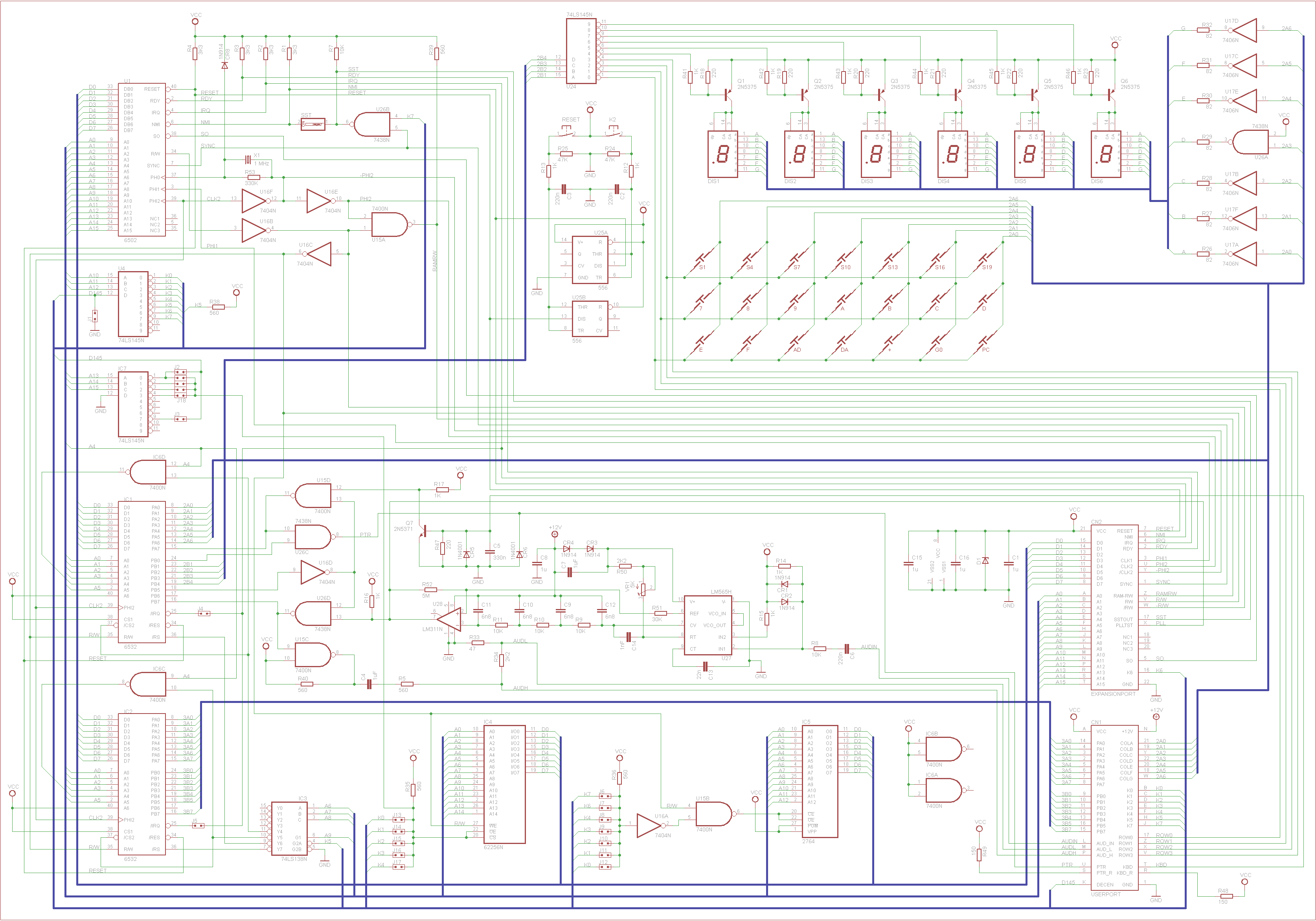
What are the major differences with the original circuit:
You may notice that Ruud did not change things which are more or less obvious like replacing the clock circuit by a module or replacing the various 74XX TTL-ICs by their LS or HCT equivalents.
(Thanks to J Coville)
Back in the day, a designer ordering a custom 6530 would have to specify certain parameters in addition to the ROM contents. During my KIM-1 restoration effort, I found a datasheet for the Synertek version of the part. The datasheet has quite a bit of information describing how to provide the ROM contents. There is also a form for “Additional Pattern Information” (tables to describe the desired chip-select and addressing information). They look like this:
Chip Select Code (Check one square in each block)
|
|
|
|
ROM/RAM/I-O SELECTS (Specify H or L or N (don’t care) in each box.)
RS | CS1 | CS2 | A9 | A8 | A7 | A6 | |
ROM Select | N | N | N | N | |||
RAM Select | |||||||
I/O Select |
As best as I can determine, the designers of the KIM-1 filled out the tables for the RRIOTs like so:
6530-002:
|
|
|
|
RS | CS1 | CS2 | A9 | A8 | A7 | A6 | |
ROM Select | L | H | N | N | N | N | N |
RAM Select | H | L | N | H | H | H | H |
I/O Select | H | L | N | H | H | L | H |
6530-003:
|
|
|
|
RS | CS1 | CS2 | A9 | A8 | A7 | A6 | |
ROM Select | L | H | N | N | N | N | N |
RAM Select | H | L | N | H | H | H | L |
I/O Select | H | L | N | H | H | L | L |
In a KIM-1, K5 is asserted low by addresses 1400-17FF. It is connected to the CS1 lines of both the 6530-002 and 6530-003. A9 and A8 need to be 1 for all I/O and RAM, and A6 and A7 determine which chip and I/O or RAM you get:
0001 0111 00XX XXXX = 1700 – 173F = 6530-003 I/O
0001 0111 01XX XXXX = 1740 – 177F = 6530-002 I/O
0001 0111 10XX XXXX = 1780 – 17BF = 6530-003 RAM
0001 0111 11XX XXXX = 17C0 – 17FF = 6530-002 RAM
The RS lines are connected to different select lines, K6 for 6530-003 and K7 for 6530-002, this gives:
0001 10XX XXXX XXXX = 1800 – 1BFF = 6530-003 ROM (1k)
0001 11XX XXXX XXXX = 1C00 – 1FFF = 6530-002 ROM (1k)
All these values agree with the KIM-1 memory map documentation.
K0 $0000 – $03FF 1024 bytes of RAM (8*6102)
K1 $0400 – $07FF free
K2 $0800 – $0BFF free
K3 $0C00 – $0FFF free
K4 $1000 – $13FF free
K5 $1400 – $16FF free
$1700 – $173F I/O, timer of 6530-003
$1740 – $177F I/O, timer of 6530-002
$1780 – $17BF 64 bytes RAM of 6530-003
$17C0 – $17FF 64 bytes RAM of 6530-002
K6 $1800 – $1BFF 1024 bytes ROM of 6530-003
K7 $1C00 – $1FFF 1024 bytes ROM of 6530-002
K0..K7 = output lines from 74145
MOS Technology designed two ICs that look very similar, the MCS6530 and the MCS6532.
The 6532 is called RIOT, for RAM I/O and Timer. The 6530 is called RRIOT, for ROM RAM I/O and Timer.
The timer and I/O is (nearly) identical on both IC’s. RAM is 64 byte on a 6530, 128 byte on the 6532.
The ROM is where the big difference is, it is a 1K so called mask programmed ROM. This means the contents of the ROM are determined in the factory.
Besides the ROM also at the factory choices can be made about the Chip and Register Select lines and such.
The 6532 is a general purpose I/O IC and widely used because of its versatility.
Of the 6530 a limited number of variants were made by the factory as I. The 6530 variant is often indicated by a number, 6530-XXX.
Well known variants are the 6530-002 and 6530–003 used in the KIM-1. The 6530-004, called TIM, is used in the Jolt computers. In many Commodore disk drives 6530 variants are used. .
Information on this page:
The 6530, nick named RRIOT is quite a special IC in the 65xx family.
Timer, RAM (64 byte), ROM, I/O, Counter in one IC. It has a factory mask programmed ROM and the locations of its I/O and RAM and ROM are determined also in the factory.
The 6530 is found in among others the KIM-1 (6530 02, 6530 03), a Chess system with MicroChess by Peter Jennings (6530 24) and variants are used in Commodore disk drives.
The 6532 has no ROM and RAM size is 128 byte versus 64 in 6530. I/O and timer are functional identical to the 6530. The nickname is RIOT, and it is a general purpose I/O device in the 6502 family. Very popular in e.g. the Atari 2600, and many clone KIM-1’s.
There is a datasheet for an IC called the 6531, RRIOC for RAM ROM I/O Counter. I have never seen it in the wild though, but seen references to pinball machines using it.
A mistery 6530, 021 unknown sofar.
The Micro-KIM, see the whole story here, is another variant of a KIM-1 with the original ROMS and 6532 instead of 6530.
See the complete circuit (version 2009!) here.
Use a KIM-1 (clone) to read out a 6530-009
TODO: add 6530-009 rom bin and assembly