The KIM Uno, designed and produced and (once) sold by Oscar Vermeulen, is a very simple “open-source hardware” project that started out as a replica of the classic 1976 KIM-1 computer plus built-in ‘early 6502 software gems’ collection. Later, Apple-1 compatibility and a 6502 programmable calculator mode were added, and a Cosmac Elf emulation.
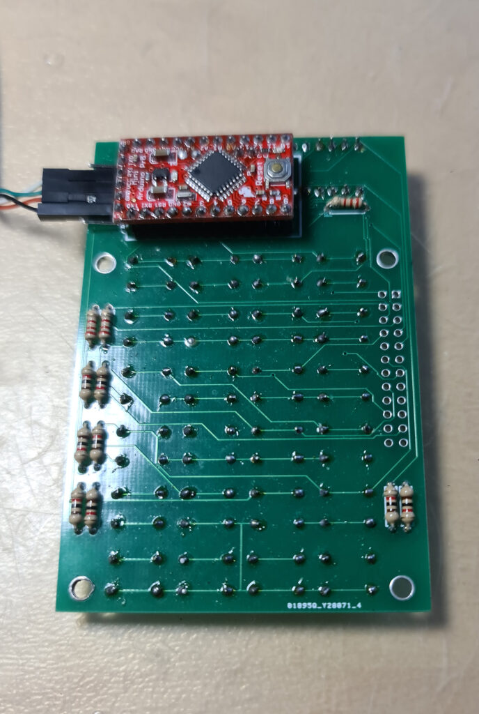
It is a low cost project and provides a faithful KIM-1 ‘experience’. An Arduino Pro Mini mounted on the back contains all the logic and memory, the front is a replica of the KIM-1 keyboard and LED display.
On this page
As Oscar Vermeulen describes it:
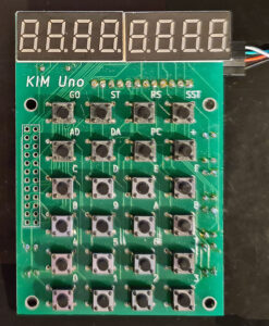
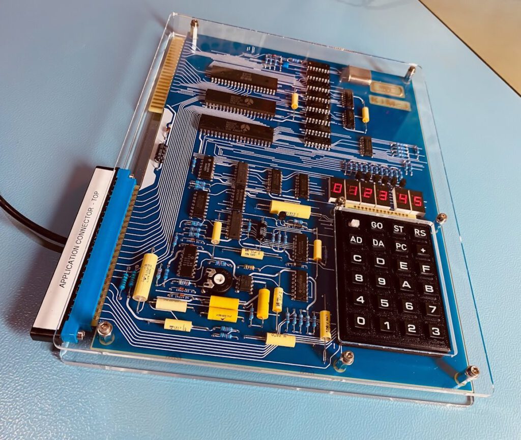
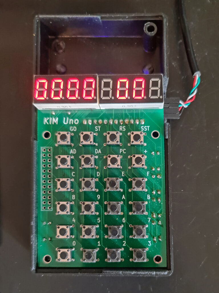
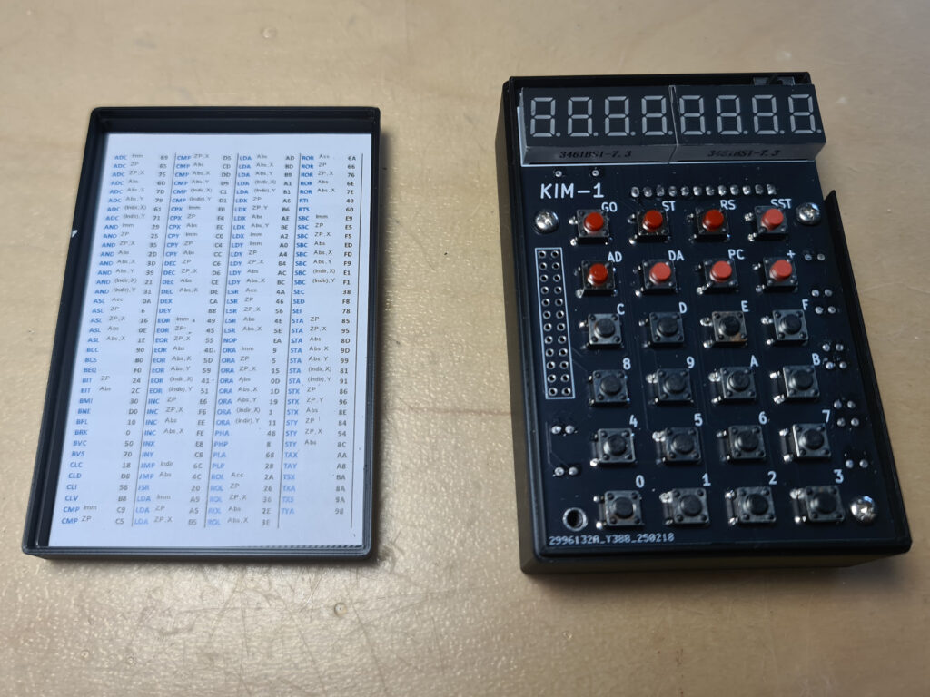
The front side of the board provides the user interface as the KIM-1 offered it back in 1976: a keypad and segment LED digits. The only differences are:
- A toggle button instead of a slide switch for SST
- Display with 7 instead of 6 digits, and adding decimal points.
These extras are not used in KIM-1 mode, but allow the Calculator Mode to display floating point numbers.
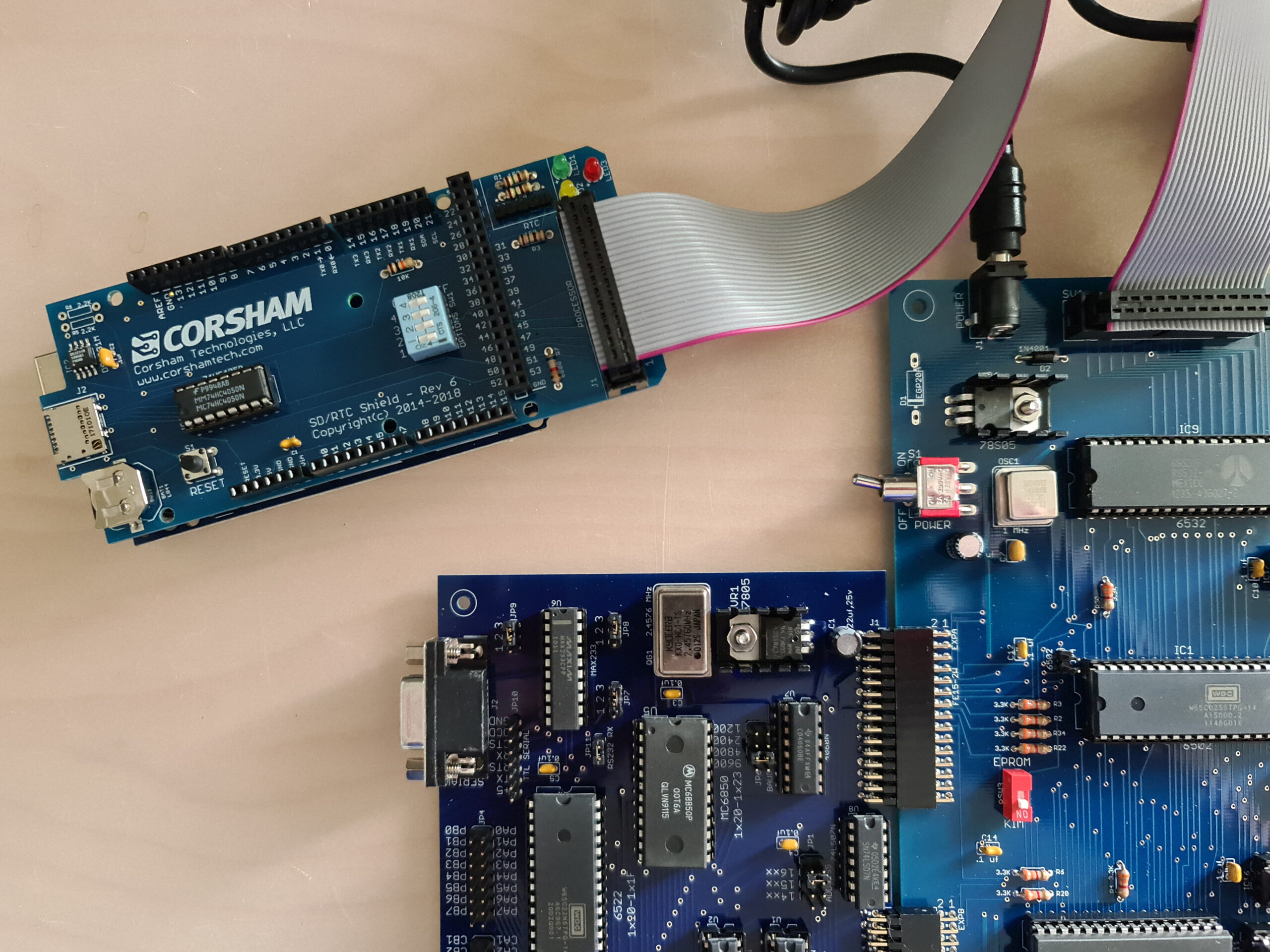
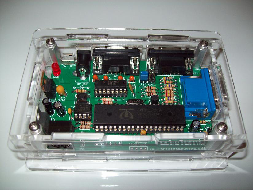
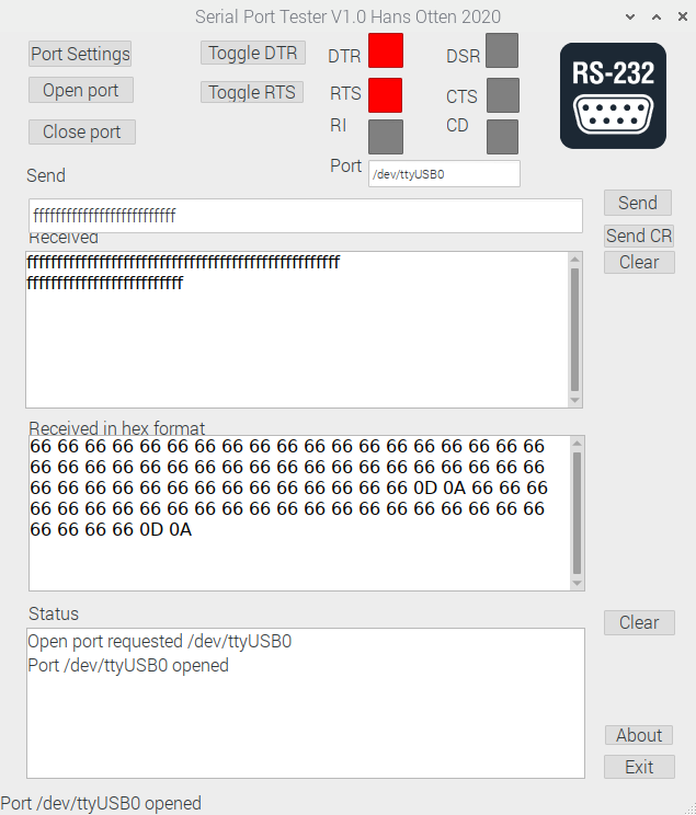
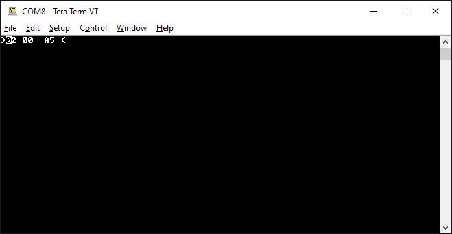
The KIM’s serial port is also present, so you can hook up the KIM Uno to a terminal/PC terminal emulator just like the original.
The KIM Uno contains some extra ‘ROMs’ with vintage KIM software:
- Programming tools to disassemble, move & relocate code. The goal was to power up the KIM Uno with all the development tools that were loaded from tape and/or soldered on ROM cards back in the 70s.
- Microchess to play chess.
- Fltpt65, a floating point math library, that enables the KIM Uno to be a 6502 programmable calculator.
- VTL-02 is a Basic-like language, showing this can actually be done in 1020 bytes.
- Apple 1 Wozmon monitor and A1Basic
- Storage is provided through the atMega’s 1K eeprom, pretending to be a cassette tape.
As it turned out, it was easy to make the KIM Uno compatible with the KIM-1 and Apple-1 at the same time. So, WozMon and an Apple-1 version of the Apple mini-assembler were built in too.
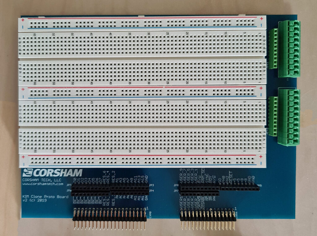
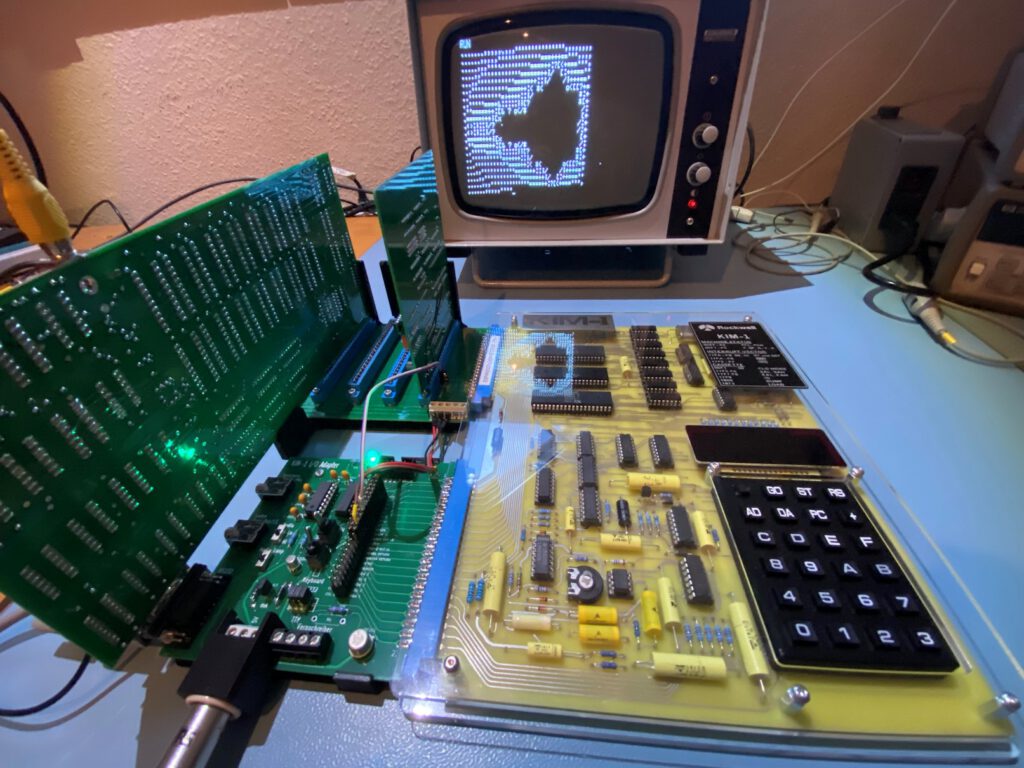
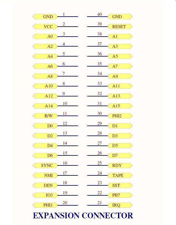
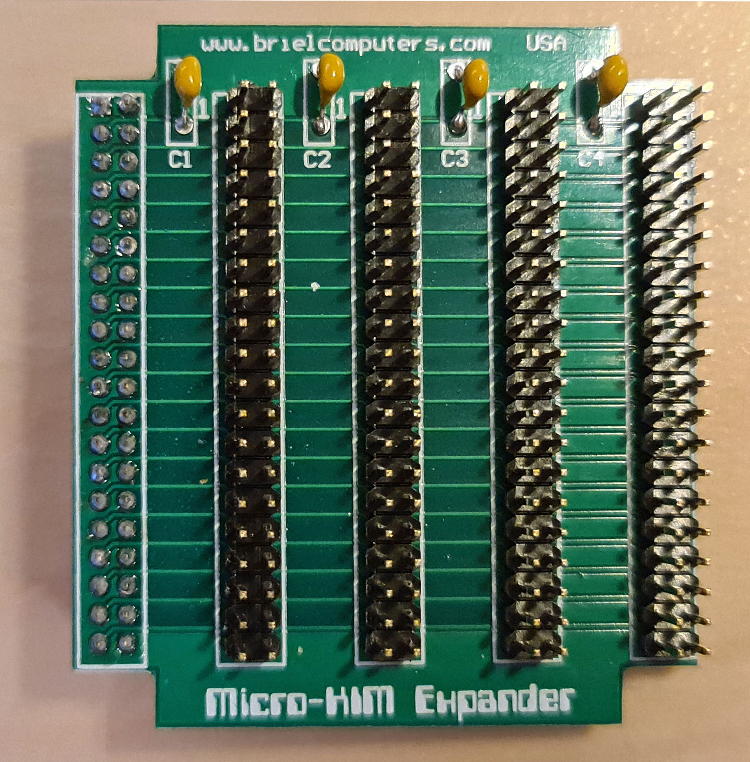
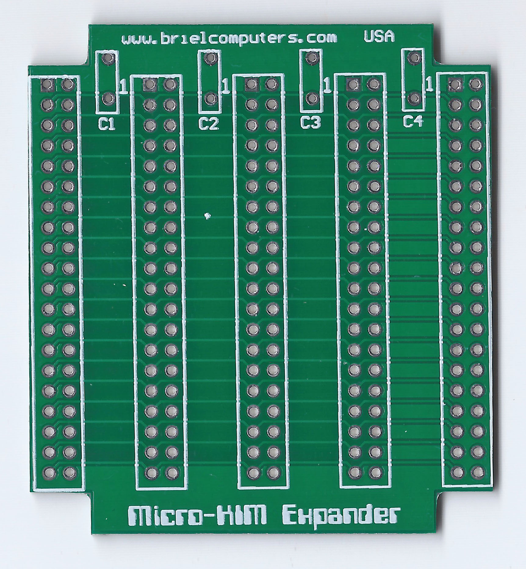
The original KIM-1 had an Expansion Connector. Although not supported by the ROM, it was there for whatever hardware hacks a user wanted to add. The KIM Uno has its own version of it, providing I2C and SPI. All sorts of cheap components could be hooked up, from a little OLED display to sensors, motor drivers, etc.
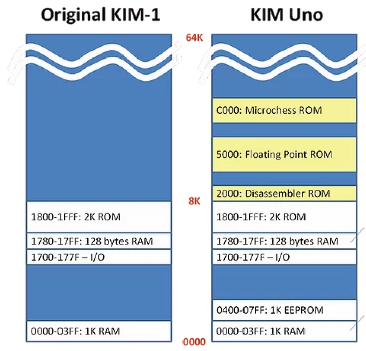
The memory map shows what the KIM UNO is capable off. A KIM-1 with ROMs (at choice when building the firmware) is the best description available. No RAM above 2000, so the TTY software available for a KIM-1 with extra RAM is not usable. Lower RAM limited to 1K.
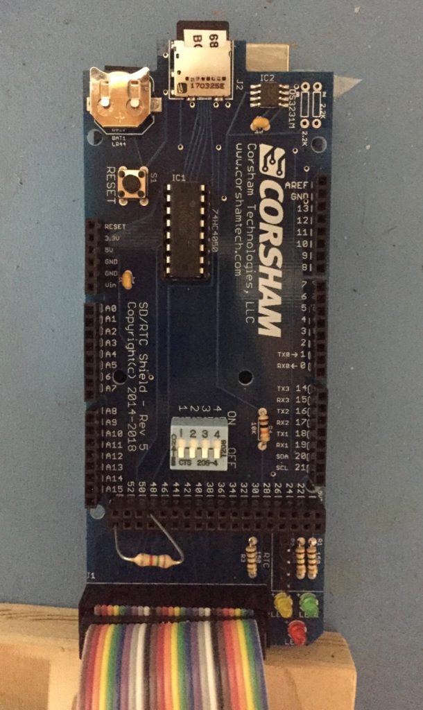
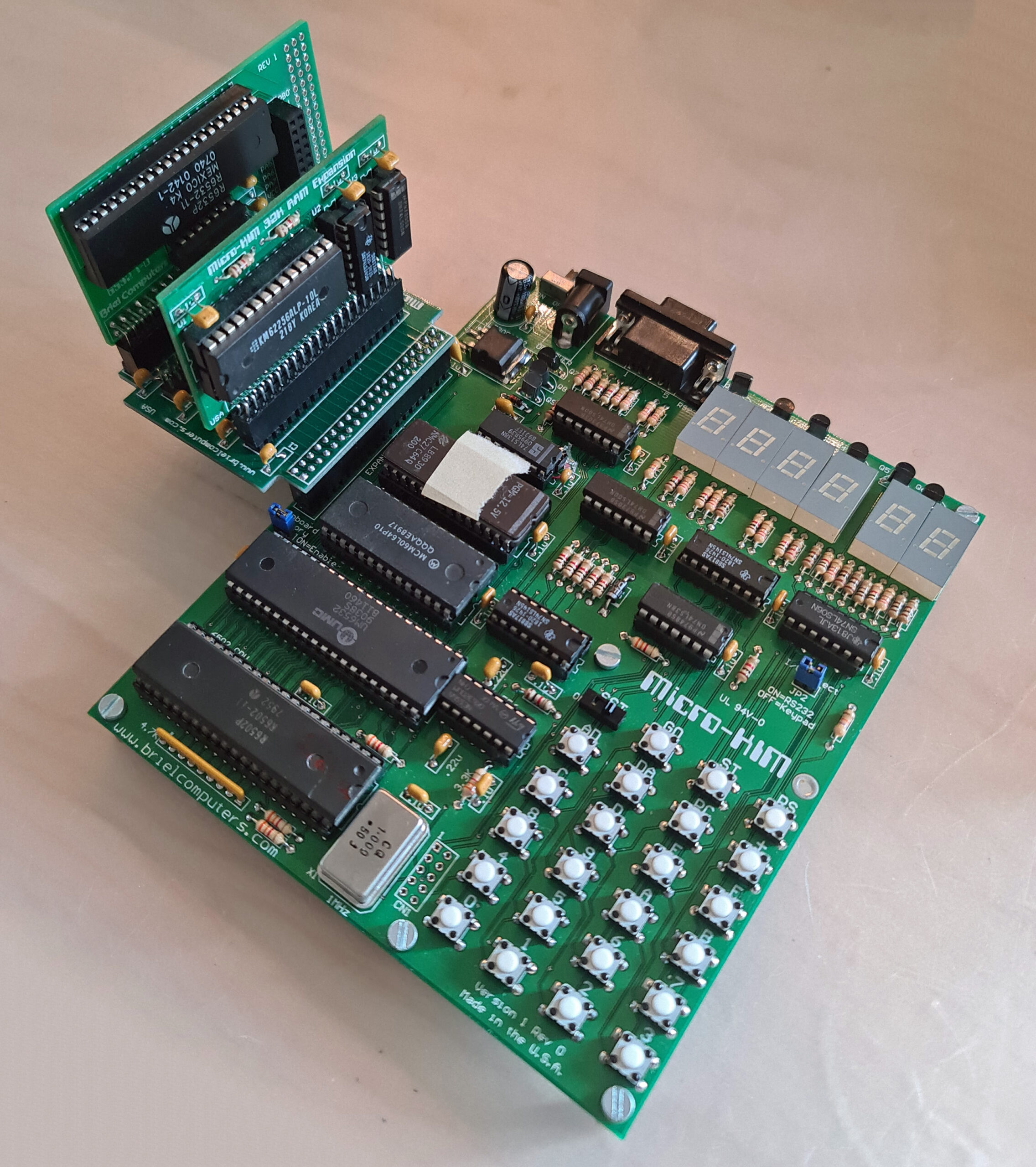
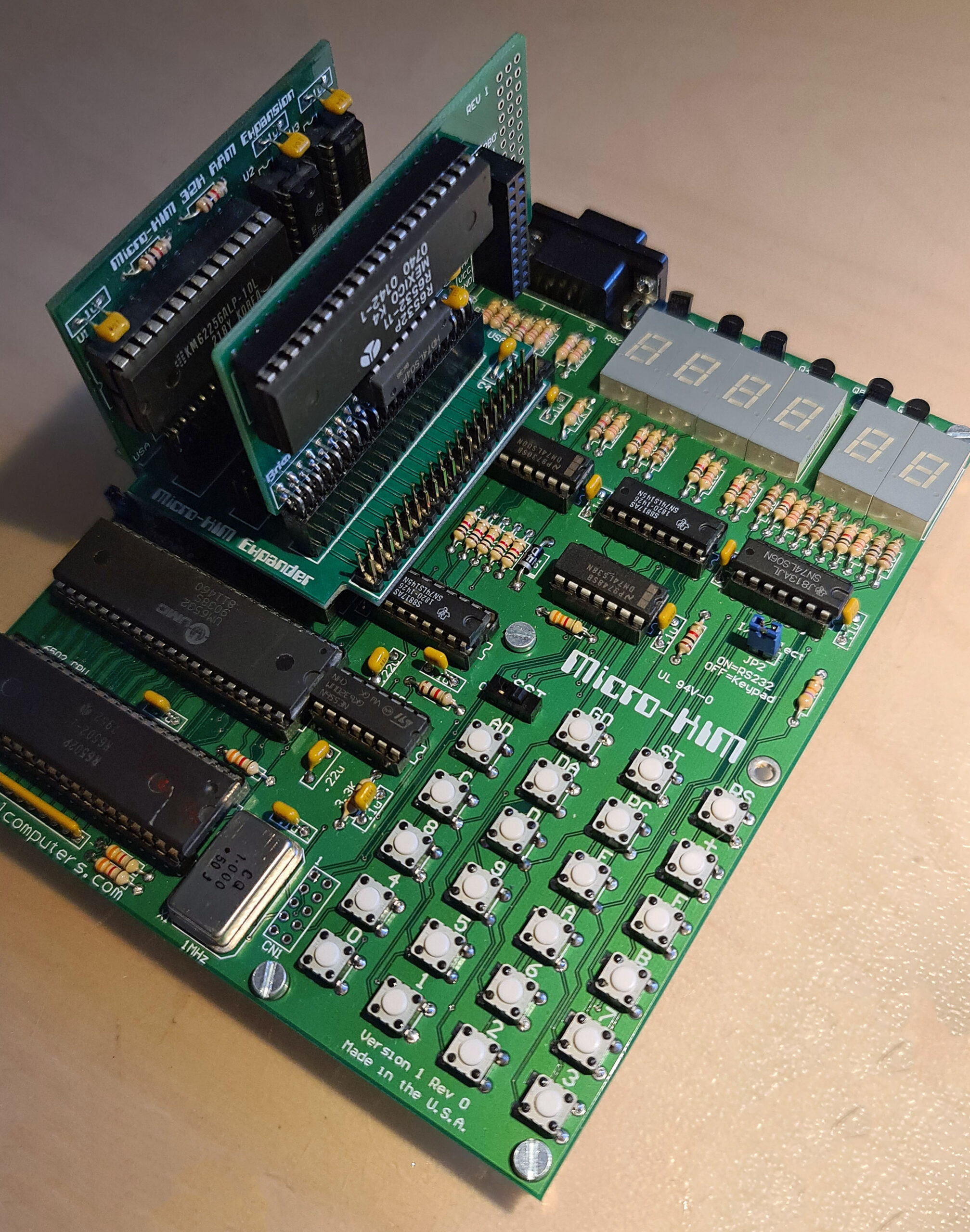
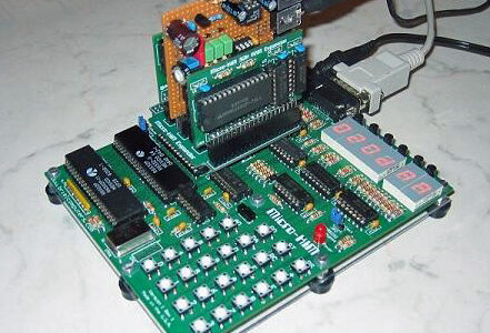
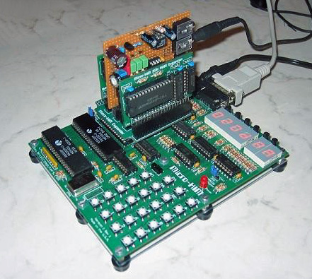
KIM UNO hardware

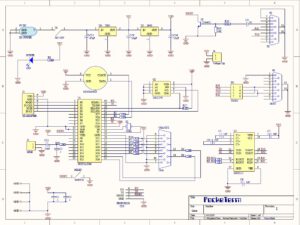
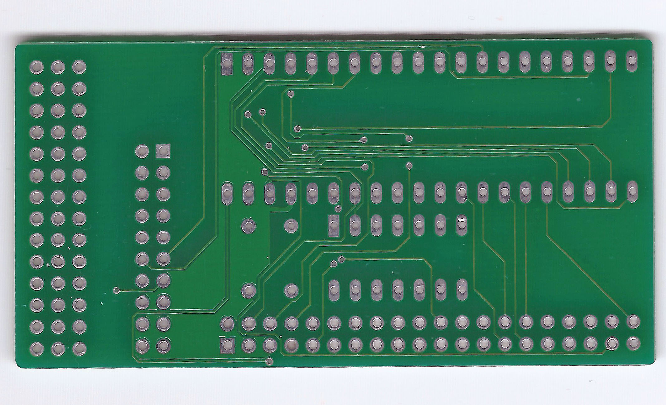
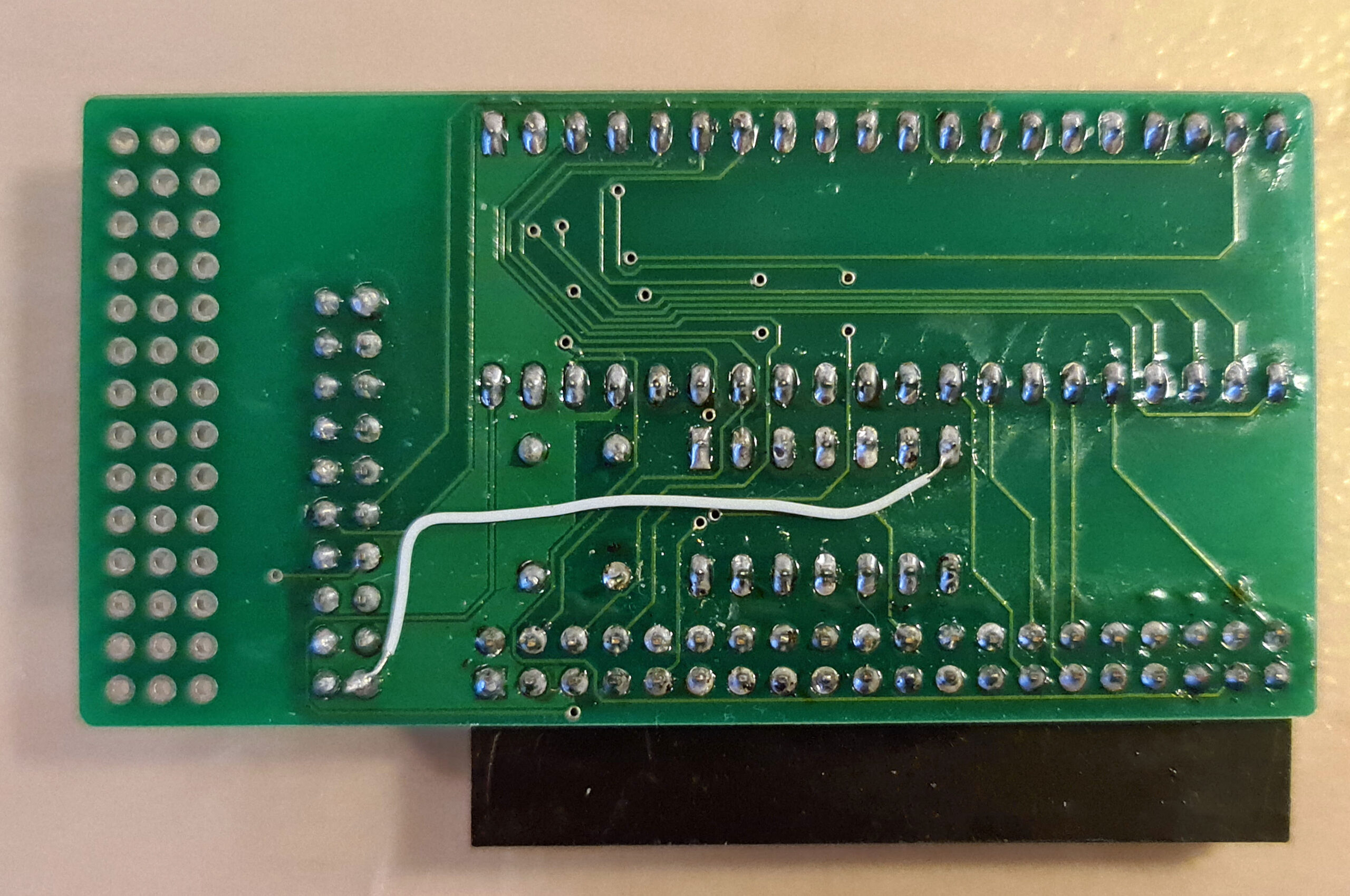
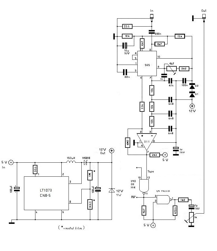
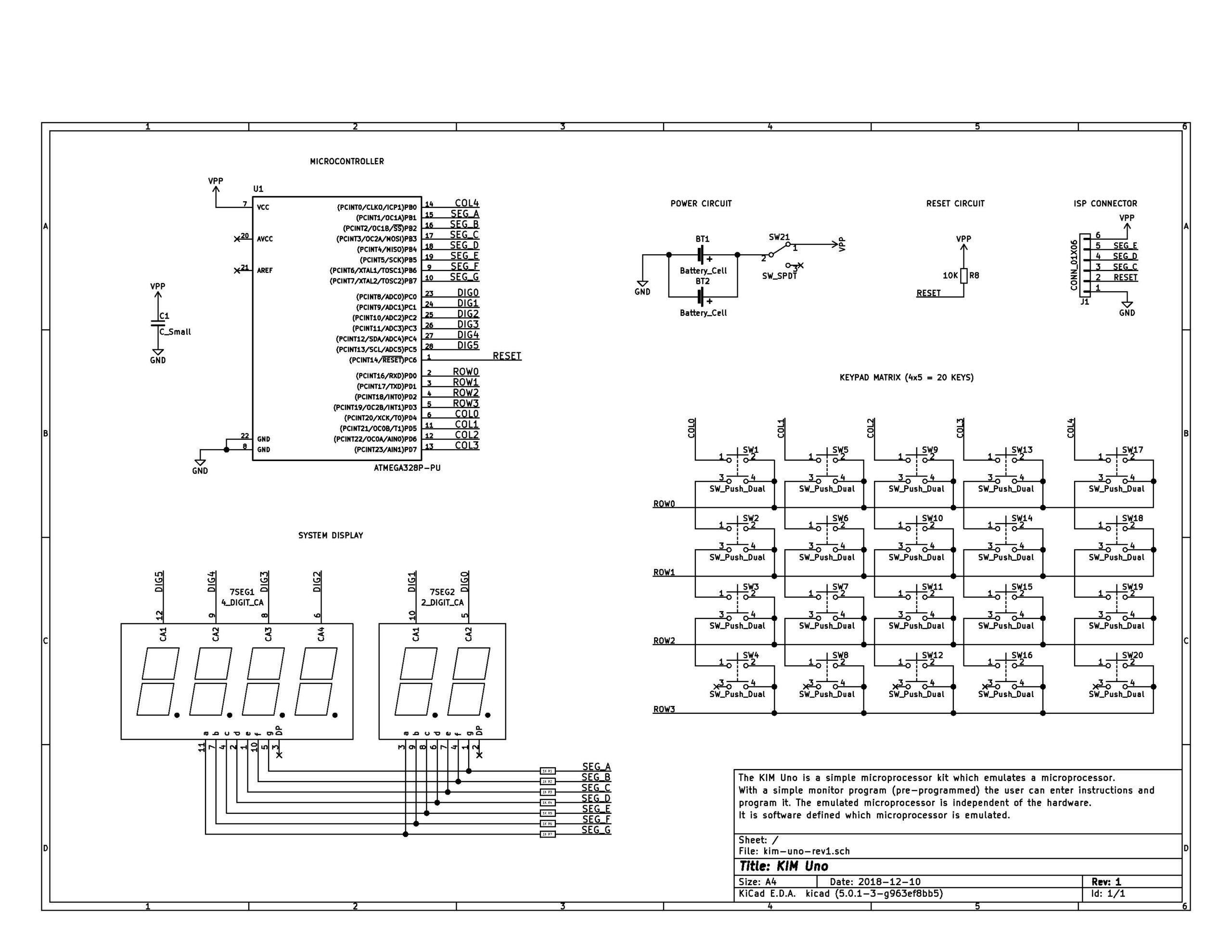
The KIM UNO circuit
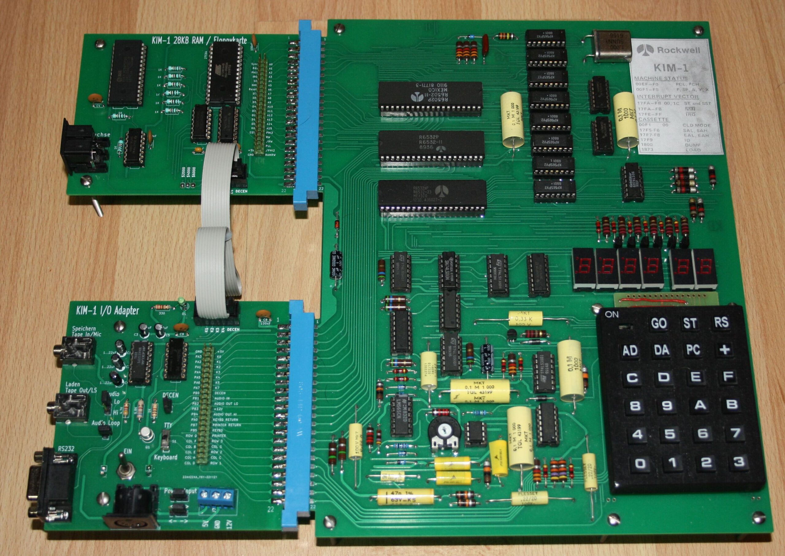
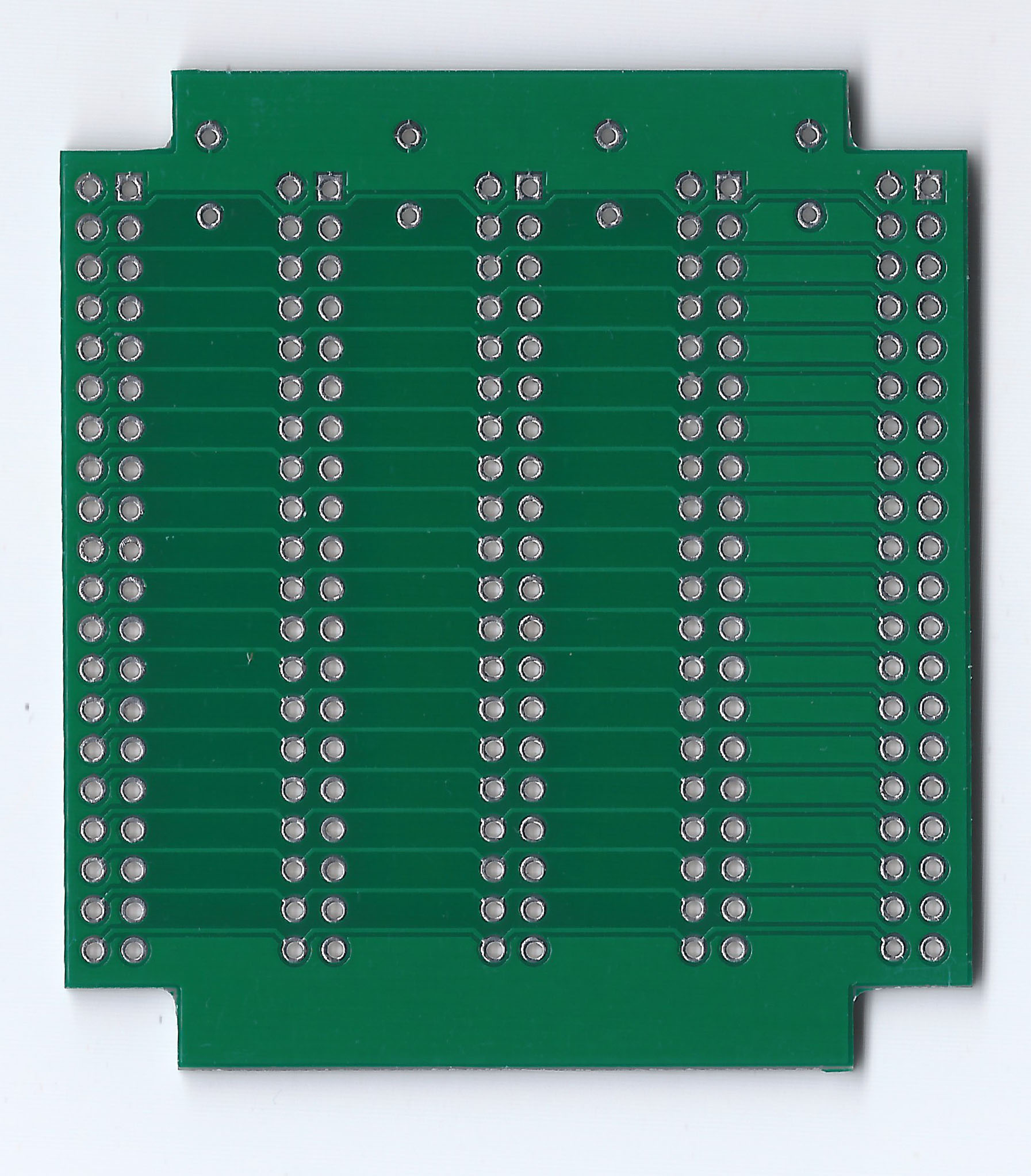
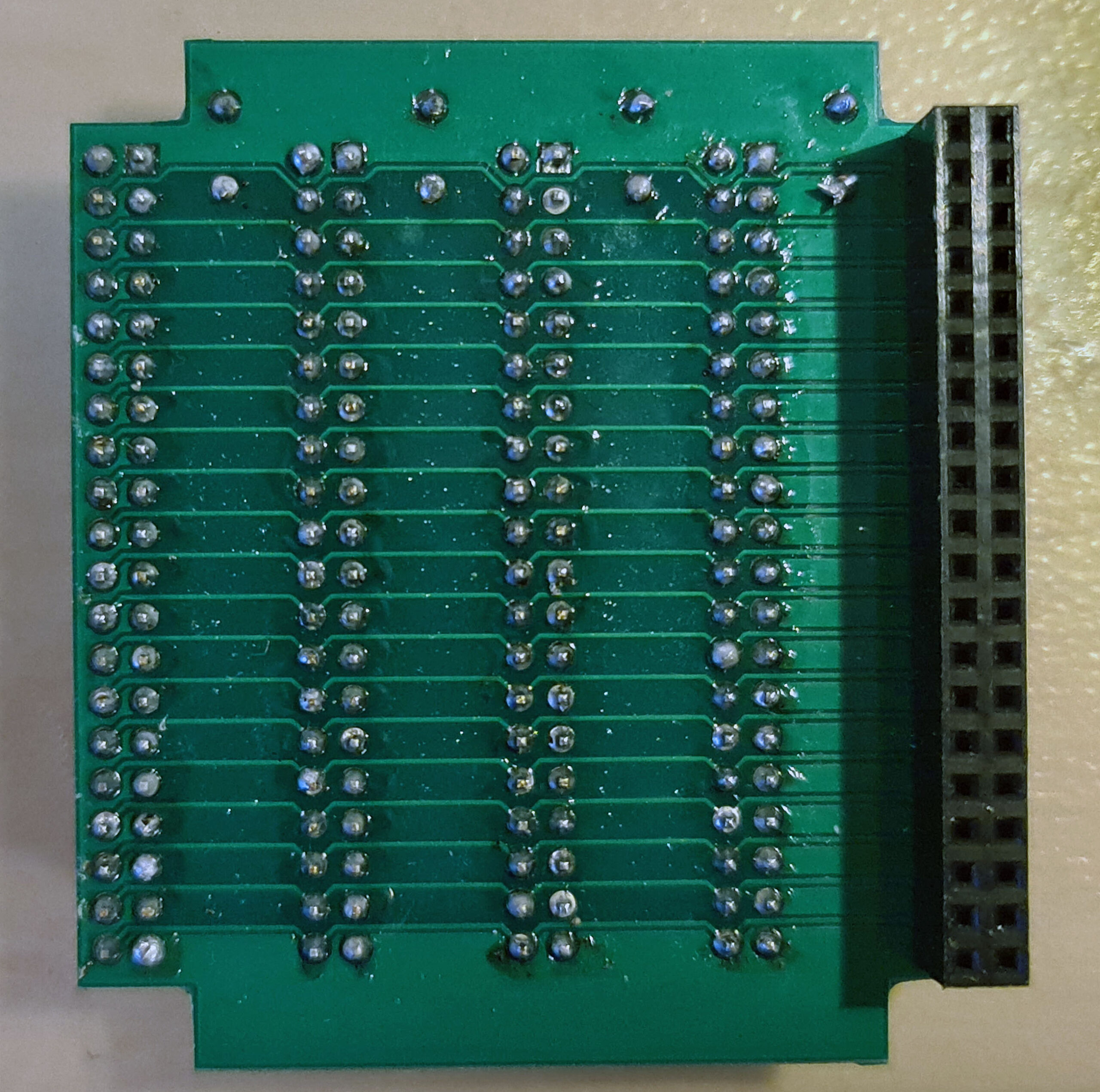
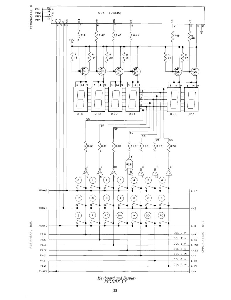 The original KIM-1 Keypad and LED display circuit
The original KIM UNO
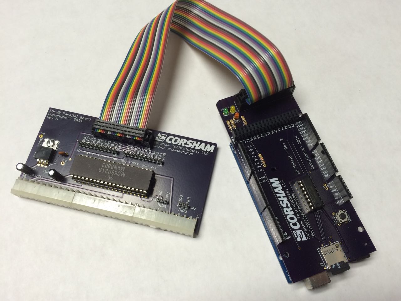
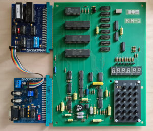
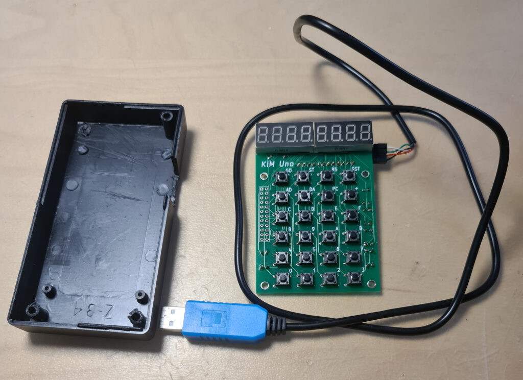
I have two versions of the kits designed and sold by Oscar Vermeulen: the ‘original’ and the redesigned version in 2020. Functional the same, with on the top of the PCB room for power connector (GND, +5V or a 9V battery) and a slide switch. , I use them with an USB cable delivered by Oscar (the blue one of this page) for power and the serial interface provided.
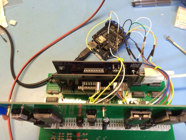
The software already works on the blue pill STM32 or an ESP32, with manual cabling to the keyboard/display.
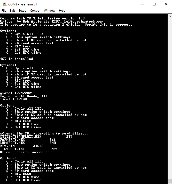
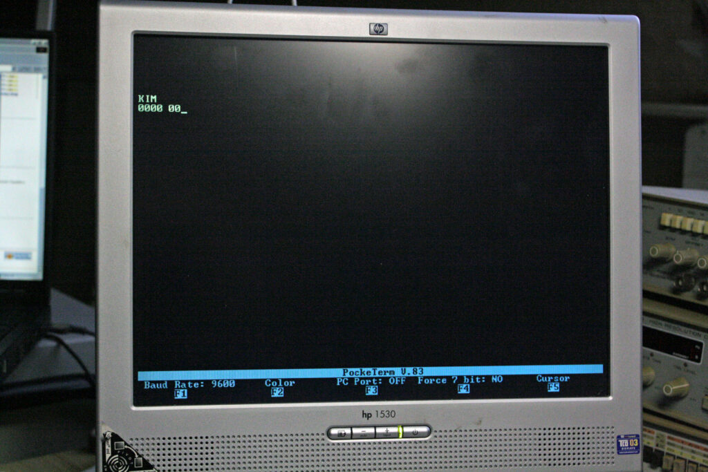
The software for the serial interface (you really need a good serial terminal emulator, like Minicom or Tera Term) can be used on any Arduino Uno. After power on it delivers a simulation of the LED display and the real KIM TTY teletype interface.
All well described on the pages of Oscar and well worth the money for a ‘6502 SBC’ experience.
I have several KIM UNO’s. The second version one with a slide switch for battery or external power supply. Boxed in the case supplied by Oscar in the kit.
Also a unbuilt second version.


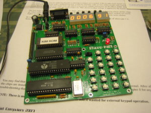
KIM UNO by retrobit4004
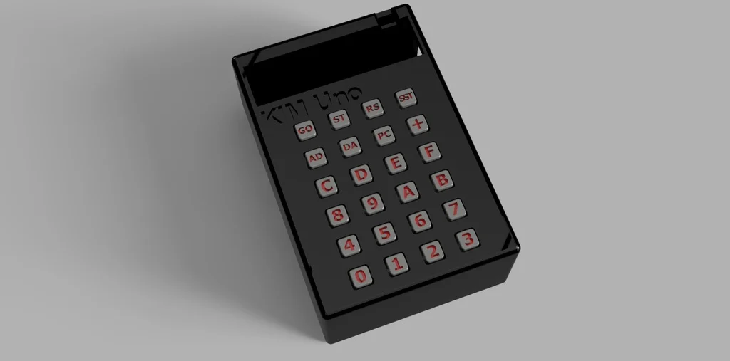
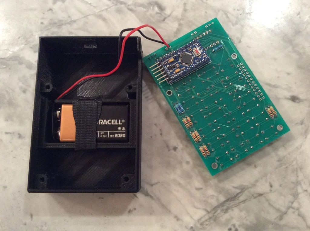
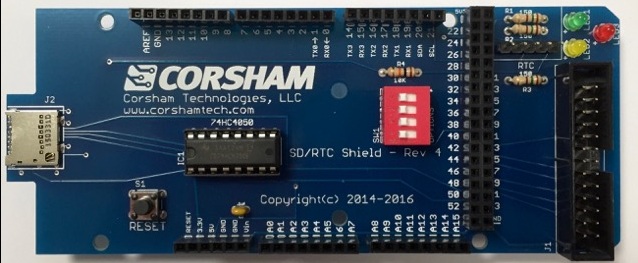
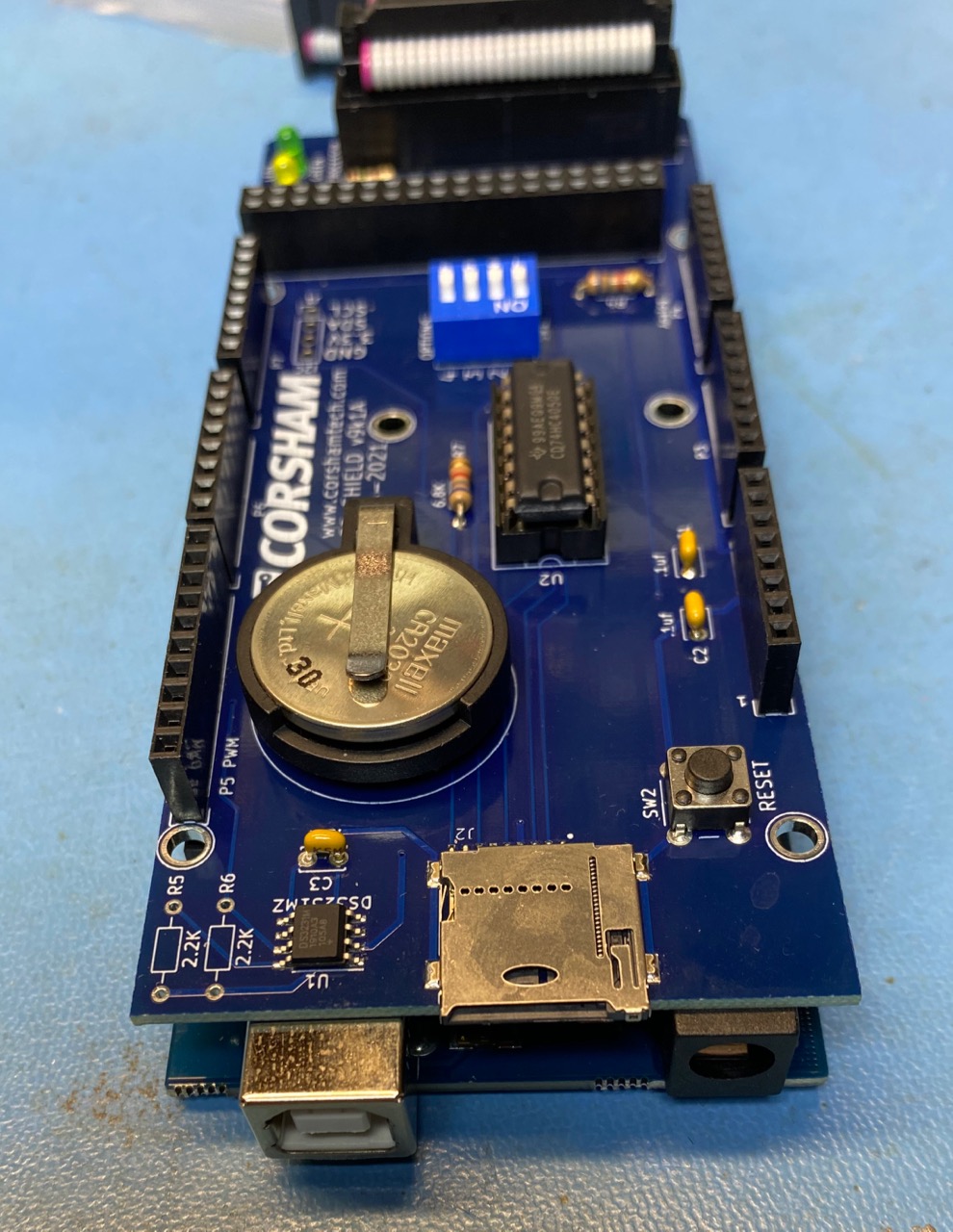
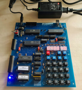
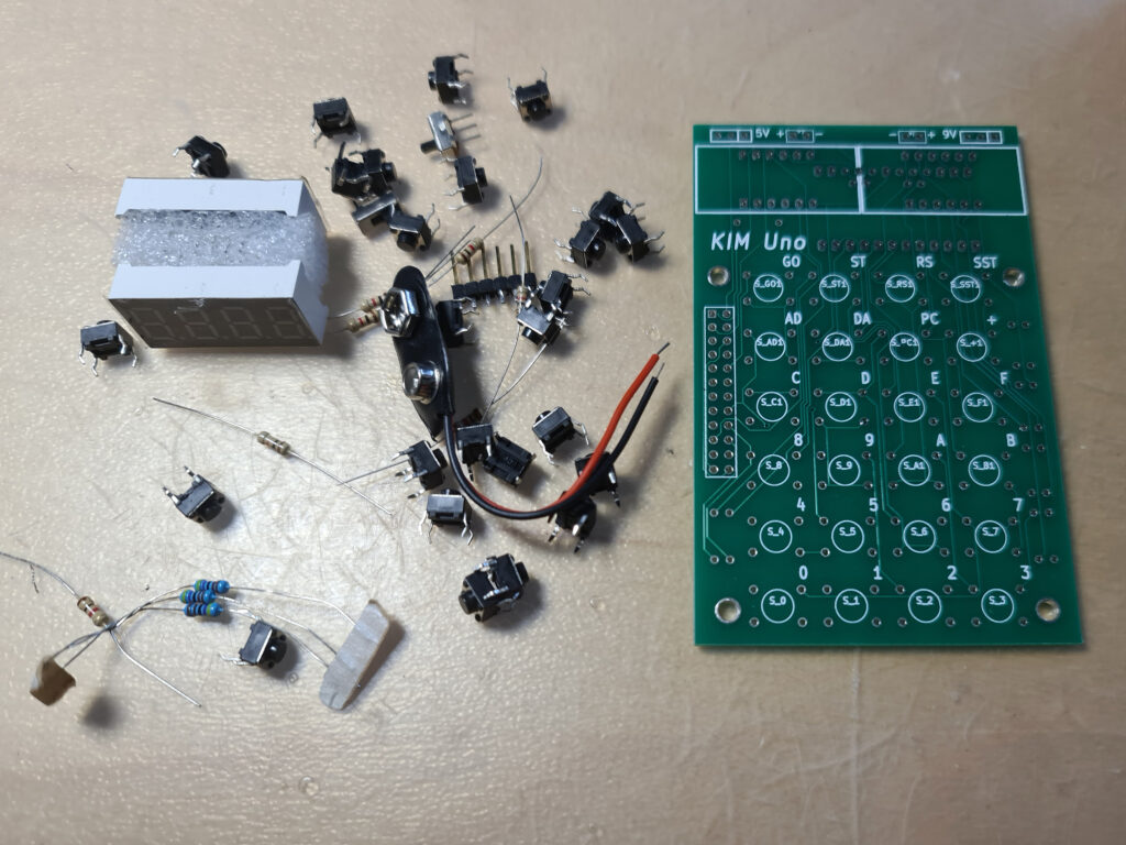
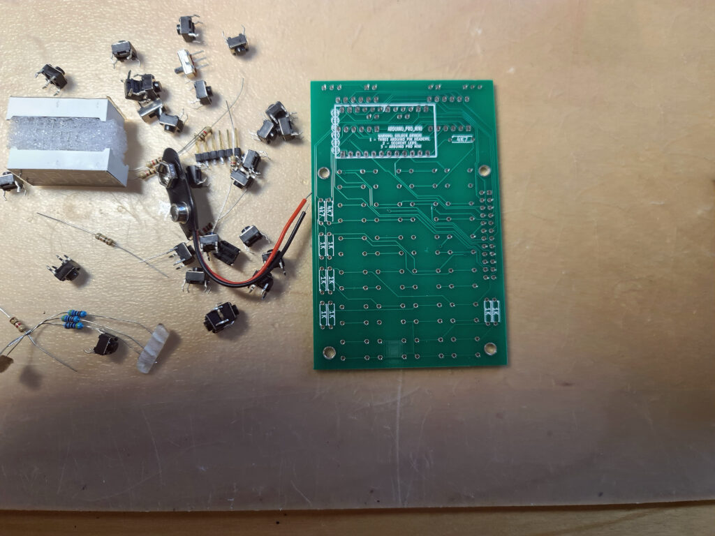
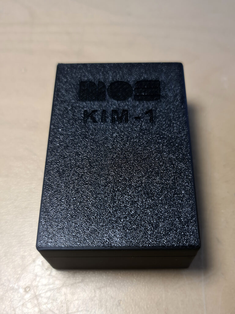
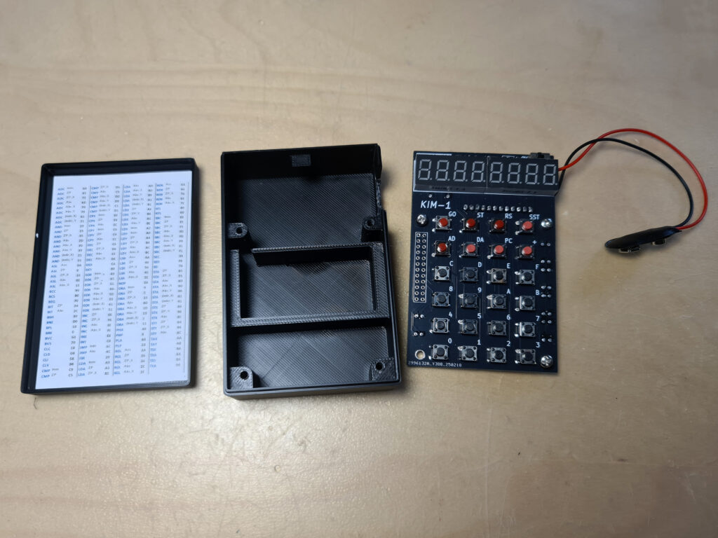
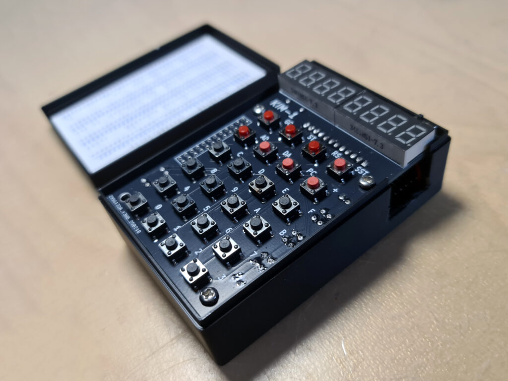
In 2025 I bought a build version from an Italian seller on ebay (retrobit4004). In a nice 3d printed case with a battery compartment, an updated PCB (Oscar supplies the Kicad design files). Alas the connector on the Arduino is soldered wrongly upside down, so I had to cut out more space at the side part.
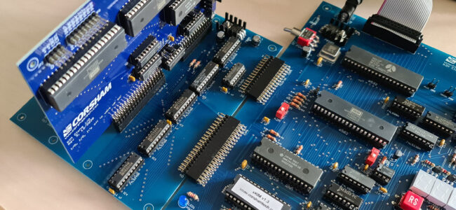
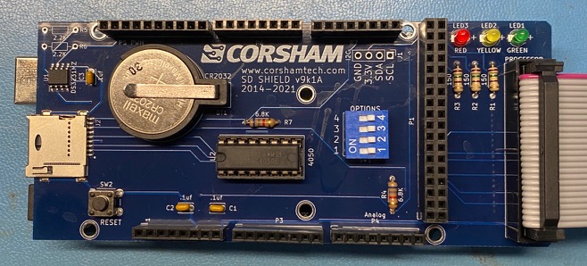
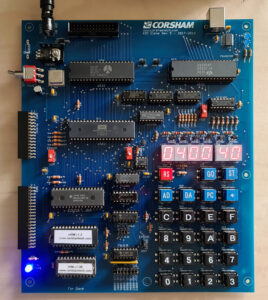
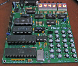
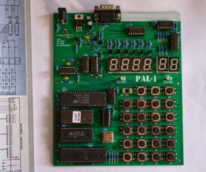
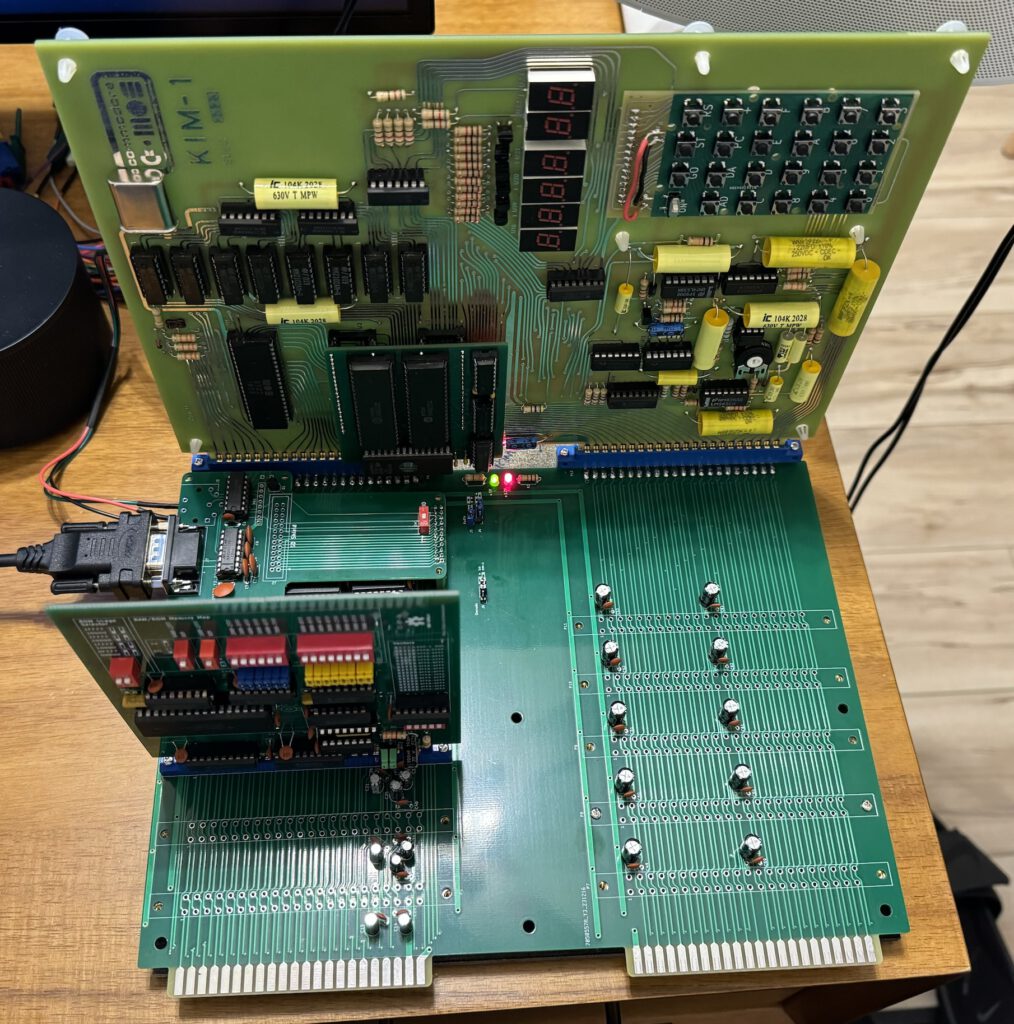
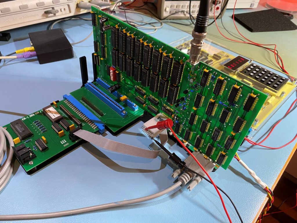
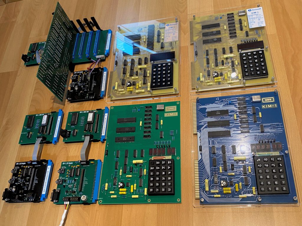
The different versions of the PCBs in my kits.
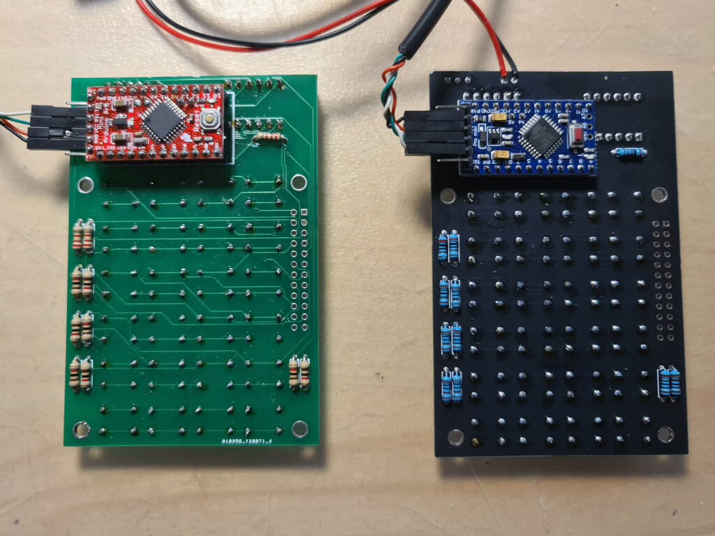
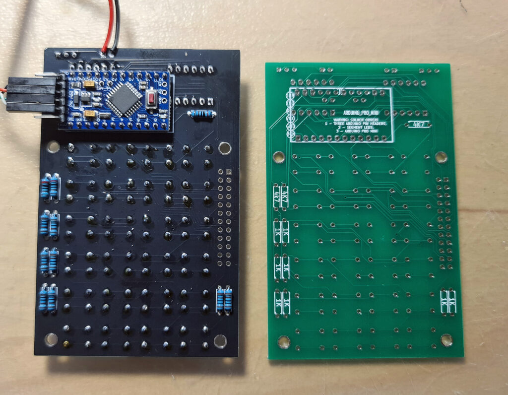
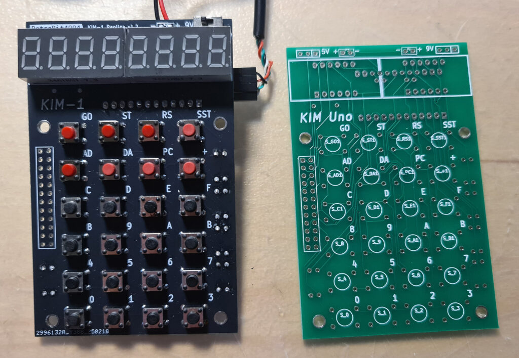
To my surprise the Arduino Pro mini in the retrobit4004 version has the pins on the side for serial and power supply mirrored, as you can see in the photos the USB serial cable.
Not a real problem, but something to be aware of! This KIM-1 (not labeled KIM UNO but it is!) works fine.
Firmware for the KIM UNO
Oscar provided firmware for the Arduino IDE that emulates a 6502 and the KIM-1 hardware. The 6502 core is a (fixed) Mike Chamber’s 6502 CPU emulation.
The KIM-1 ROMs are patched so that the keypad and LED display functions as the KIM-1, and the same for the TTY routines. That means not all First Book of KIM software works if the program addresses the ports directly. Oscar added also the Apple 1 Wozman monitor.
The Arduino IDE (even the current version) allows uploading the firmware. Note that the config.h file needs to be edited to check or uncheck wanted pieces. Not everything is possible due to the limited size of the AtMega flash memory.
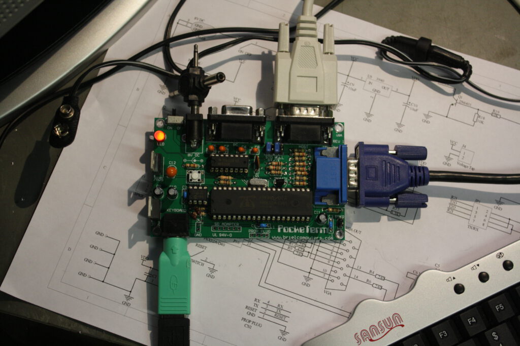
If, like me, have the ‘blue’ USB to serial adapter supplied by Oscar, look at the photos above how to connect the four connectors.
Also read the PL2303 Prolific page how to use this adapter in Windows 10 and later. Also when compiling the firmware, press the Reset button on the Arduino UNO and when uploading notice appears in the Arduino IDE, release the Reset button. It may take several tries, but uploading will succeed in the end.
Alternative firmware
In the Links section you find a link to the firmware developed by others:
- Coscmac Elf 1802 emulation
- Adapted firmware with direct port addressing by Willem Aandewiel
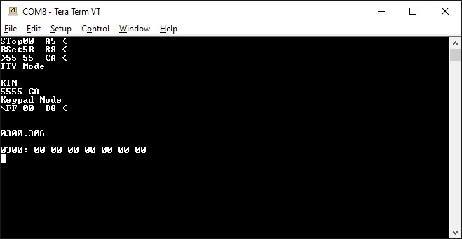
Pressing control keys to perform ST and RS key
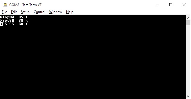
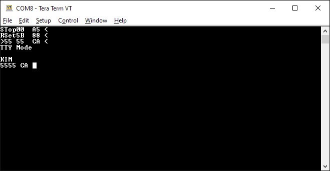
Press TAB to get into KIM TTY mode. Make sure to select on your terminal Local Echo and CAPS Lock. Read the
KIM-1 User manual how the monitor operates.
 The Apple 1 mode, fully functional.
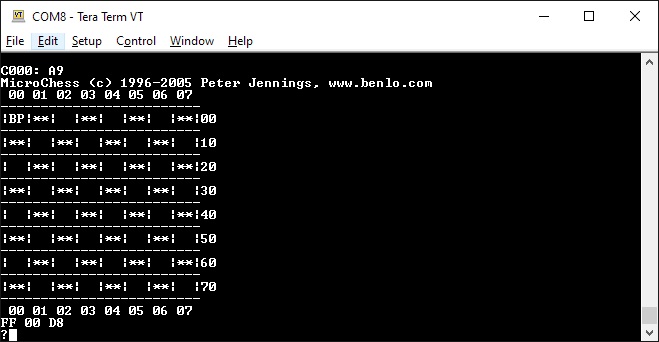 Microchess adapted to serial
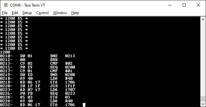 The Wozniak/Baum disassembler
Links to websites with KIM UNO information.
As usual with external links, this may fail in the future. I have local copies so that will replace lost websites.
Let me know via the Contact page
3d design for KIM UNO cases
3d case with keypad buttons
3d case line retro4004bits is using
Another 3d case with keypad buttons