KIM-1 Simulator
Hans Otten, Eduardo Casino, 2019- 2026, Version 2.3.0
Contents
Installation
Installation requires several steps. Please read these instruction for the operating system you are using.
Downloads
Setup for Windows and Ubuntu and Raspberry Pi 5 and macOS, Version 2.3.0
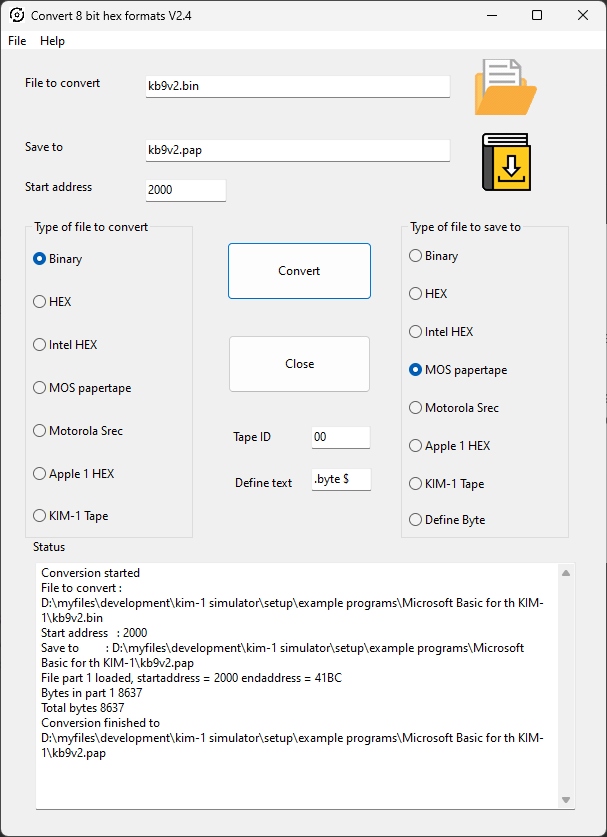
Bundled with Conversion 8 bit hex formats utility, to convert to/from various binary files like MOS Papertape, Intel Hex, Motorola S-record and more.
Source (requires Lazarus IDE 2.x), and is not required for running the Simulator
Unpack the downloaded KIM1SIMV211.zip (or higher version if published) in a folder on your hard disk, e.g. c:/KIM1SIM
This will create a folder and file structure like this:
Convert8bithexformat V28.zip
example programs
K-1008  C header loader
K-1013
macOS
Raspberry Pi 5
readme.txt
SDCARD
ubuntu
Windows
Windows
Run KIM1SIMsetup.exe or place the files KIM1SIM.EXE file in a folder of choice or leave it in the KIM1SIM/Winwos folder.
For high DPI screens change for the the file KIM1SIM.EXE (click right on the file)
– Properties – Compatibility settings – Change high DPI settings
– check high DPI scaling Override,
– scaling performed by “System(enhanced)”.
Now proceed to Settings after installation
Linux (Ubuntu, Raspberry Pi)
Execute KIM1SIM from the folder where you unpacked the Linux archive
Now proceed to Settings after installation
macOS
- Unzip the file
- Move the KIM1SIM app to Applications
- Remove quarantine:
$ xattr -dr com.apple.quarantine /Applications/KIM1SIM.app
Settings after installation
Any setting you change is stored, so next time you start the Simulator it will be set at the last value.
First start the KIM-1 Simulator and choose Settings to set the default working directory. Otherwise files may appear at locations you do not want!
The other settings are described at the applicable paragraph. It is recommended to keep the folders underneath the KIM1SIM folder you create at the first step.
Introduction
The KIM-1 simulator is developed for personal use to aid in developing and testing software for the KIM-1. It is not meant to be a cycle exact complete KIM-1 emulation. Instead it shows as much as possible what is happening inside the KIM-1. So do not expect it to run the typical KIM games on the LED and Keypad.
Just for fun and a tribute, it looks and feels and functions as a real KIM-1. Console TYY mode and the debugger is what the purpose of this program is.
The program is developed on Windows, Linux and MacOs. Since the source is available, it will run anywhere the Lazarus IDE is available.
What is simulated
- 6502 or 65C02 CPU (only documented behaviour)
- KIM- LEDs and keypad
- TTY in and out with local TTY console or serial port local or remote
- 6530-002 and 6530-003 ROM
- The suppress ‘echo TTYecho’ hardware
- The TTY/LED input bit
- KIM-1 Tape load and save
- Apple 1 Wozmon monitor
- MTU K-1008 Visable Memory video display
- SD Card/RTCShield interface by Bob Applegate from Corsham Technology
with CP/M-65 and XKIM operating systems
- K-1013 MTU floppy disk interface with CODOS and CP/M-65 operting systems
-
- A video console that emulates a DEC VT100 and more
Limitations
What the KIM_1 Simulator does not do as the real KIM-1:
- Light the LED segments from the RRIOTs outputs. Instead the SCANDS routine is intercepted and the LEDs show the hex output of location F9 FA FB.The simulation is not cycle exact enough to perform the KIM-1 way of flashing the LEDs. So some First Book of KIM type programs will not work.
- The TTY in and out routines are intercepted and rerouted to an ACIA emulation. See the ACIA routines.
- The upper pages are not mapped to the lower pages as in most KIM-1 configurations. The vectors at FFFA etc are pointing to the KIM-1 ROM vectors, so RESET. NMI and IRQ work.
- Tape hardware is not emulated, a software emulation is available
- No hardware single-step via NMI, the debugger has much better facilities for that/
- The CPU runs as fast the host CPU allows, and lets the host operating system do some work like key and display and other applications running and continue the emulation loop until the user stops the 6502 CPU. A Slow down button in the Settings tries to slow down to about a 1 MHz cloved 6502.
The speed is therefore dependent on the host CPU. Running the classic Clock program, showing a HHMMSS clock on the LEDs, on my Intel core I7 one minute real time has the clock show 1 hour 37 minutes.
The CPU is halted every 1000 clock ticks to let the GUI of the program a chance to handle mouse and keyboard and screen updates like the stop key.
This works well on modern PC’s, even the Raspberry 5!
- The CPU emulation may not be perfect, only valid and documented opcodes are implemented, especially ADC and SBC have many, not emulated here, undocumented issues.
- IRQ handling is not present in this version, see planned enhancements. NMI key works, as does Reset.
Enhancements
The KIM-1 Simulator is a KIM-1 with:
- 6502 or 65C02 CPU (make the choice in the Debugger)
- RAM to $1400
- RAM from $2000 to $FF00
- ACIA 6850 at $1600 (equal to Corsham’s I/O card)
- ROM at $1500 with 6850 ACIA support at $1620
- Pages E and F are not mapped to page 0 and 1 as in most expanded KIM-1’s.
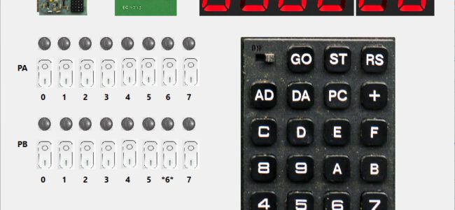
- LEDs and switches to the user RRIOT Port A and B
- Switch between TTY and LED/keypad
- Emulation of the hardware echo of TTY console input, and echo suppression trick
- MTU K-1008 MTU Visable Memory
- SD-Shield Corsham Technologies at user RRIOT port
- K-1013 MTU Floppy disk interface
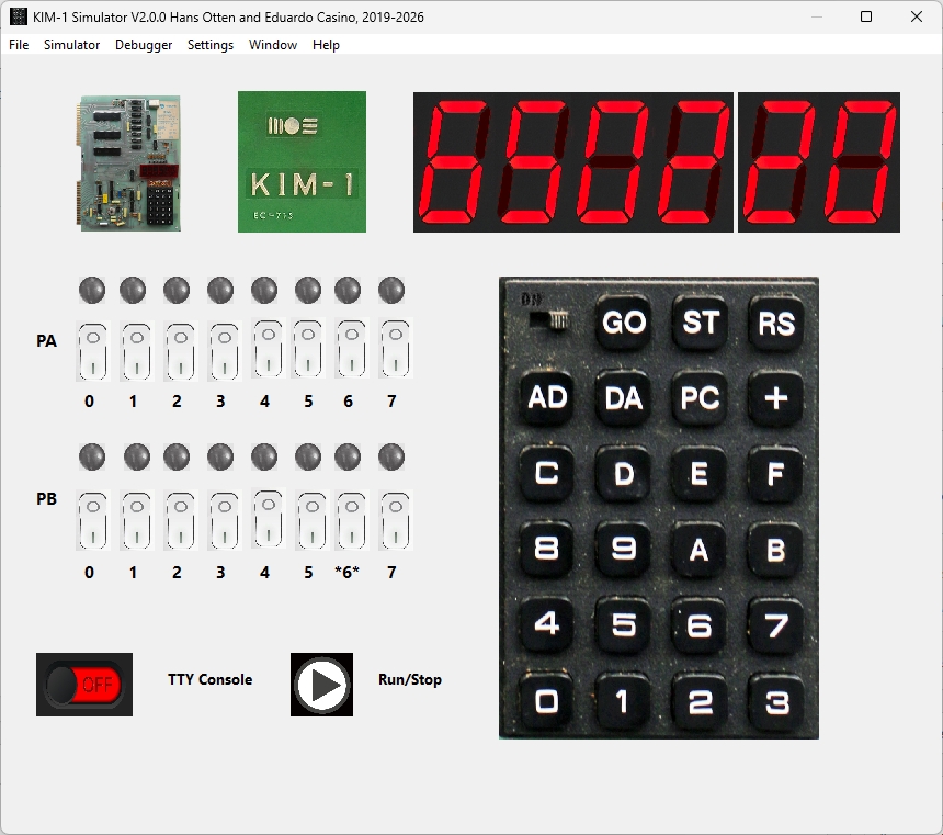
How to use as a KIM-1
Start the emulator main program and push the ‘Run’ icon. Then press the RS key on the keyboard (or type R).
After that the LEDs awake and the keyboard is operational as a KIM-1.
  [0] to [F]  -   Sixteen keys used to define the hex code
                  of address or data

  [AD]  -   selects the address entry mode

  [DA]  -   selects the data entry mode

  [+]   -   increments the address by +1 but does
            not change the entry mode

  [PC]  -   recalls the address stored in the Program
            Counter locations (PCH, PCL) to the display

  [RS]  -   causes a total system reset and a return to
            the control of the operating program

  [GO]  -   causes program execution to begin starting
            at the address shown on the display

  [ST]  -   terminates the execution of  a program and
            causes a return to the control of the
            operating program
Besides pressing the keys on the KIM keyboard on the screen you can also use the PC keyboard:
  0-9 : key 0 - 9
  a-f : key A - F
  A-F : key A - F
  +   : +
  A   : AD
  D   : DA
  P,p : PC
  G,g : GO
  S,s : ST
  R,r : RS
  S,s : ST
TTY mode, console or serial
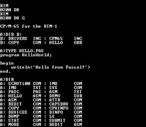
Press the TTY switch and run/stop and you have a simple console terminal. The KIM-1 teletype commands now work and also programs line KB9 Basic can be used. See the TTY Console page.
You can also, via settings, choose to have all TTY input and output got via a serial connection on your system. With some tools it can even be a local terminal emulator. See the TTY Serial page
KIM-1 Tape load and save
You can switch tape/load emulation off in Settings.
The KIM-1 tape load ($1873) and save ($1800) programs are emulated. You will see prompts when you start these from the emulator.
Fill in the tape ID and optionally start and end address as documented in the KIM-1 User manual.
Start the Save at $1800 and the load at $1873 with the KIM-1 monitor.
You will be prompted for file to load or save.
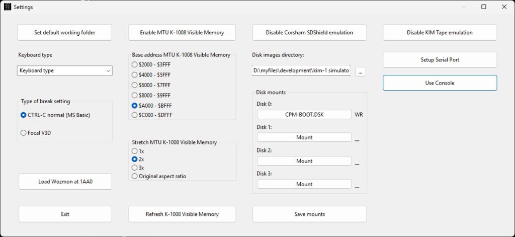
Default working directory and other settings
Use the menu Settings to display the possible settings that survive sessions.
– Set default work folder to choose a folder for all files created or used by the emulator. The settings are saved between sessions.
Default settings config file on Windows : “/home/(user)/.config/KIM1SIM.cfg” or C:\users\(user)\Appdata\local\KIM1SIM.cfg”
Loaded at startup, updated via the Settings menu.
Note the SD Card/RTC Shield emulation has its own SDCARD working directory and configuration save options.
Load and Save
The menu has Load and Save functions, you can load and save to many 8 bit binary formats as MOS papertape, Intel HEX, Motorola S record, binary and simple hex.
The 16 bit versions of Intel Hex etc are not supported.
The Define Type is a text file format output suitable for inclusion in assembler source.
The layout is as follows (all in hex)
;Start address-
<define text> <hex data>
 ..
where <define text> is what you fill in the Define text entry, may be empty.

Example:
; 1800-1805
        .byte $A9
        .byte $AD
        .byte $8D
        .byte $EC
        .byte $17
        .byte $A9
The debugger
From the menu Simulator choose Debugger to show the debug window. This windows has step/single step/run buttons, shows the registers and flags, zeropage, memory and the stack. The Trace logfile facility may store a trace of what happened.The disassembler part shows a disassembly.
Several refresh buttons let you update the current state of the machine.
Single step, RUN, trace log
First set the PC to the first instruction of the program to test.
- Step in: execute next instruction
- Step over: execute next instruction but skip JSR subroutines
- RUN: execute at maximum speed ( wait 0) or slow (wait x seconds between steps), use the STOP button to halt execution
- Step n: execute n instructions full speed
- Run to: execute instructions full instructions until the breakpoint or watchpoint location is reached or STOP pressed
- You can set 1o code breakpoints, 10 memory watch points and wacthpoinst on registers A,X,, Y and Stackpointer, press the Breakpoints and Watches button to show the form to fill in as desired.
- Trace log on/off: first set the Trace log file directory from the file Menu, then use any Step to have every instruction logged with status in the logfile and the tracelog.Note that this slows down execution a lot and the files can become large. So clean up regularly!
The file name of the log is set to KIM1SIMtrace(datestamp).log.
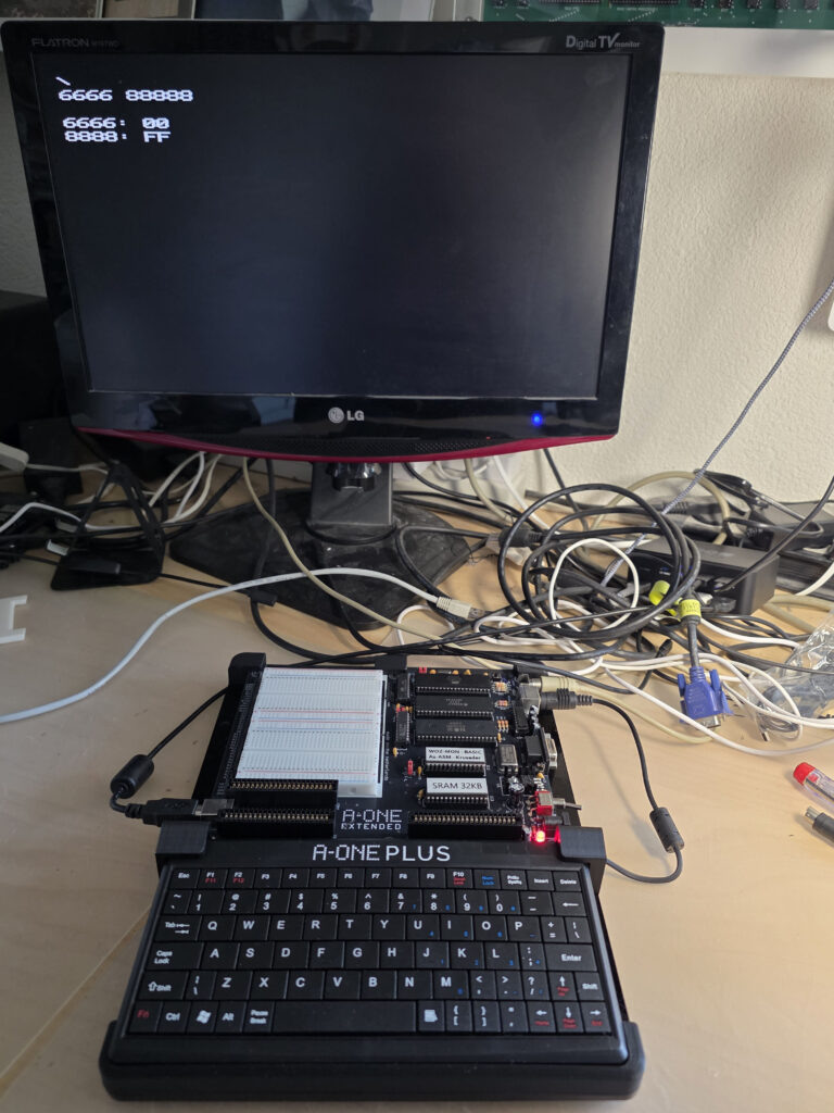
From the Search Memory you can Search with hex 1,2 or 3 bytes in memory (leave unwanted fields blank), Fill memory and Copy/Move memory.
With a fill byte you can replace the moved bytes, leave the field empty to leave the original value.
Symbol table and the disassembler
The disassembler shows locations/labels in hex format. If the assembler symbol table is available (TASM can produce that as blank delimited list) you can load it and do some symbolic disassembly.
Load and show the symbol table from the menu “Symbol table”. Supported symbol table formats: TASM 32 bit and CA65 (part of CC65 suite).
RRIOT status display
From the menu Simulator choose RRIOT to show a windows with the current RRIOT status or you can enter new values for the various registers.
Press Refresh to update to the current state, it is not updated realtime.
The 6530-002, responsible for the KIM-1 hardware, is decoded to the relevant in/output bits.
Note that the simulator does not perform the KIM-1 LED/key functions this way. Code for output to the LED displays is currently present but commented out in the source.
Timing limiting is essential for this to work, the simulation now runs as fast as the host CPU can deliver.
The Profiler
Available from the ‘watches and breaks’ form or from the Window menu
This facility keeps track (once activated with the Profiling Check box) how much an instruction is executed,
Independent of the debugger, always available.
Use the Refresh button to see the current state, not automatically updated so it is not a high performance hit.
Any opcode, from 0 to 255, is counted. The display shows the maximum 65C02 instruction set.
You can save the profiler data to a CSV file, with instruction mnemonic and number of times executed per line.
Invalid instructions are marked as ‘Unknown’.
Focal V3D from the KIM-1 Software page
Focal V3D, an interpreter modeled after the DEC PDP-8 Focal interpreter runs on the KIM-1 and on the Simulator.
This program uses a trick to suppress the echoing of charaters typed on the KIM-1 TTY hardware. And another trick to get a hash/random number.
After loading both zeropage and program code, start at $2000. But first go to sSettings and choose Focal Break testing.
Only when running Focal! Set to Normal break testing for e.g. MS Basic. This setting is not saved, and resetting the emulator makes the setting to Normal.
Example programs
In the Setup archive a folder with some TTY programs are collected. Note that manuals etc are on the Retro website.
kb9.bin	load 2000 start $4065 Microsoft KIM-1 Basic 9 digits (upercase only, set 00F1 to 0)
kb6.bin	load 2000 start $3D50 Microsoft KIM-1 Basic 6 digits (upercase only, ROR instruction patched + CLD)
kb9V2.bin	load 2000 start $3F8E Microsoft KIM-1 Basic 9 digits (upercase only, ROR instruction patched + CLD)

kimGFX.BIN 	load 2000 start 2000 Demo for K1008 video display Dave Plummer
kimGFX1.BIN	load 2000 start 2000 Demo for K1008 video display Dave Plummer

kim1sim6502test.ihex start 2000 65(C)02 opcode test (lower case y/n)

Focal
Please set in Settings Focal3D break setting
focalzp.bin load $0000
focalm.bin  load $2000 start 2000

Printing disassembler
PRDISV3.PAP start B000
The Bad Apple demoes the K-1008. See the readme.txt how to run. The emulated K-1008 is way faster than the real one, use the Slow Down button in Settings!
Compiling and building the simulator from source
If Lazarus is available then install Lazarus (Version 2 or higher) and build from source. Download (the large) KIM1SIMVxxxsource archive.
Extra packages required are LAZserial and BGRABitmap, install via the Online Package manager.
Open the project KIM1SIM.LPI and do RUN – Build to get an executable.
Prerequisites
- A modern PC and operating system. Windows 10/11 is where the software has been developed, Ubuntu are tested and binaries included.
- Development (Compile and run everywhere!) with Freepascal and Lazarus IDE, see https://www.lazarus-ide.org/
Any Lazarus version above 2.0 will be OK.
- The archive with the KIM-1 Simulator sources KIM1SIMsourcesxxx.zip.
- Unpack in a folder, avoid blanks in folder and filenames
- Start the IDE by clicking on KIM1SIM.lpi
- Build with Run – Build
- On Windows a Setup installable can be made with Inno Setup, KIM1SIM.iss and compile with Inno Studio.
The include files with KIM ROM and 6502 code
If and when the ACIA routines and other routines in the KIM1SIM ROM are altered you need to rebuild the KIM1SIMrom.inc file.
Subfolder ‘romtoconst’ contains the binary of the original KIM ROMS (6530-002.bin, 6530-003.bin) and the additional ROM binary with ACIA routines (kimsimrom.bin).
The .inc files for the compilation of the KIM1SIM, to be placed in the main folder, are created with the program creatINC.exe, a console application (source included here).
Copy the the tree .inc files to the main folder and compile the KIM1SIM program again.
D:\myfiles\development\kim-1 simulator\romtoconst\creatINC.exe
kimrom002 include file created
kimrom003 include file created
kimsimrom include file created
Folder KIM-1 assembler sources
Here you find assembler sources of various tests. Assemble with TASM, included in the folder. See TASM.HTML for information.
It is convenient to compile from an editor like Notepad++, plugin NPPEXEC
with command to create intel hex file
"D:\myfiles\development\kim-1 simulator\KIM-1 assembler sources\tasm" -65 -x3 -g0 -s $(FILE_NAME) $(NAME_PART).ihex $(NAME_PART).lst -s $(NAME_PART).sym
or to create a binary file with
"D:\myfiles\development\kim-1 simulator\KIM-1 assembler sources\tasm" -65 -x3 -g3 -s $(FILE_NAME) $(NAME_PART).bin $(NAME_PART).lst -s $(NAME_PART).sym
Note that also symbol files are generated which can be read in by the debugger in the KIM-1 Simulator.
- kim1sim6502test.asm : The 65(C)02 test, a program that runs on the TTY console
- kimsimrom.asm : the source of the KIM-1 Simulator ROM at $F000 with ACIA support for KIM-1 TTY in/out
- Various snippets used to test the CPU emulation
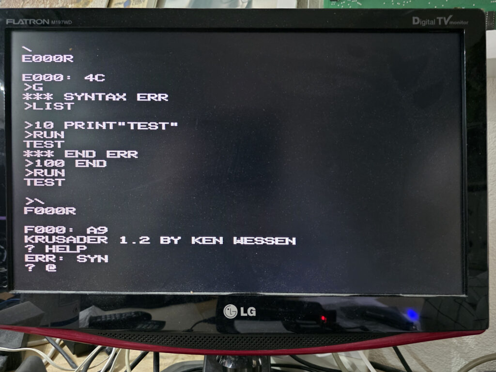
Use the Apple 1 monitor (Wozmon)
Load in Settings the Apple 1 monitor (wozmon) into the free space of the KIM-1 tape ROM.
Start at $1AA0, back to KIM-1 monitor with ‘X’ command.
Changelog

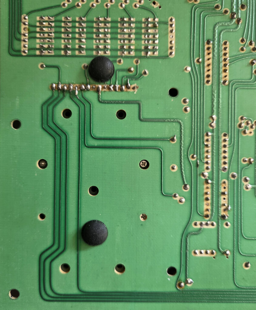
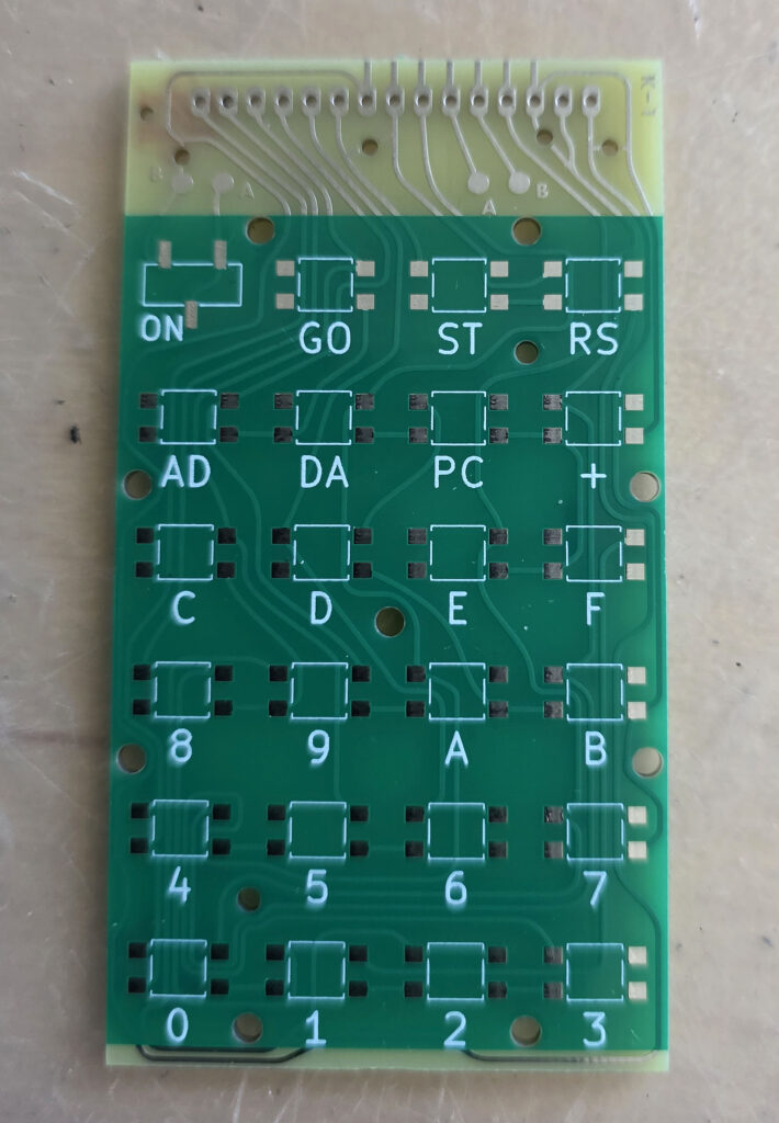
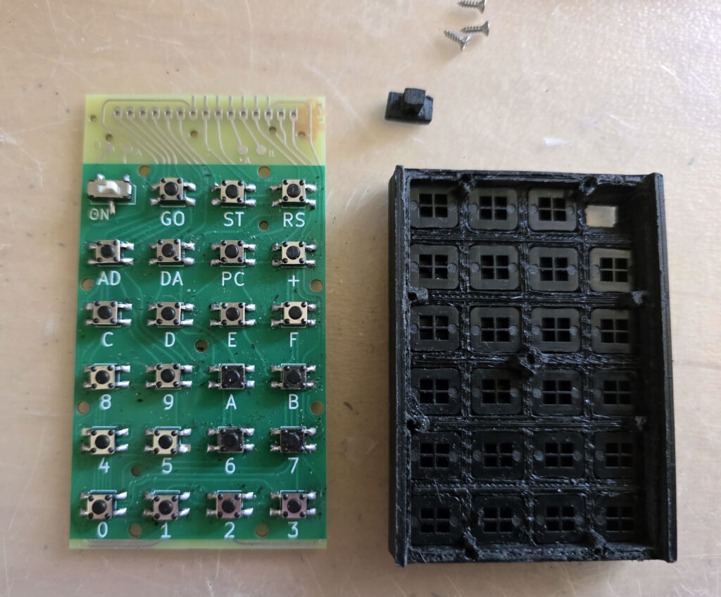
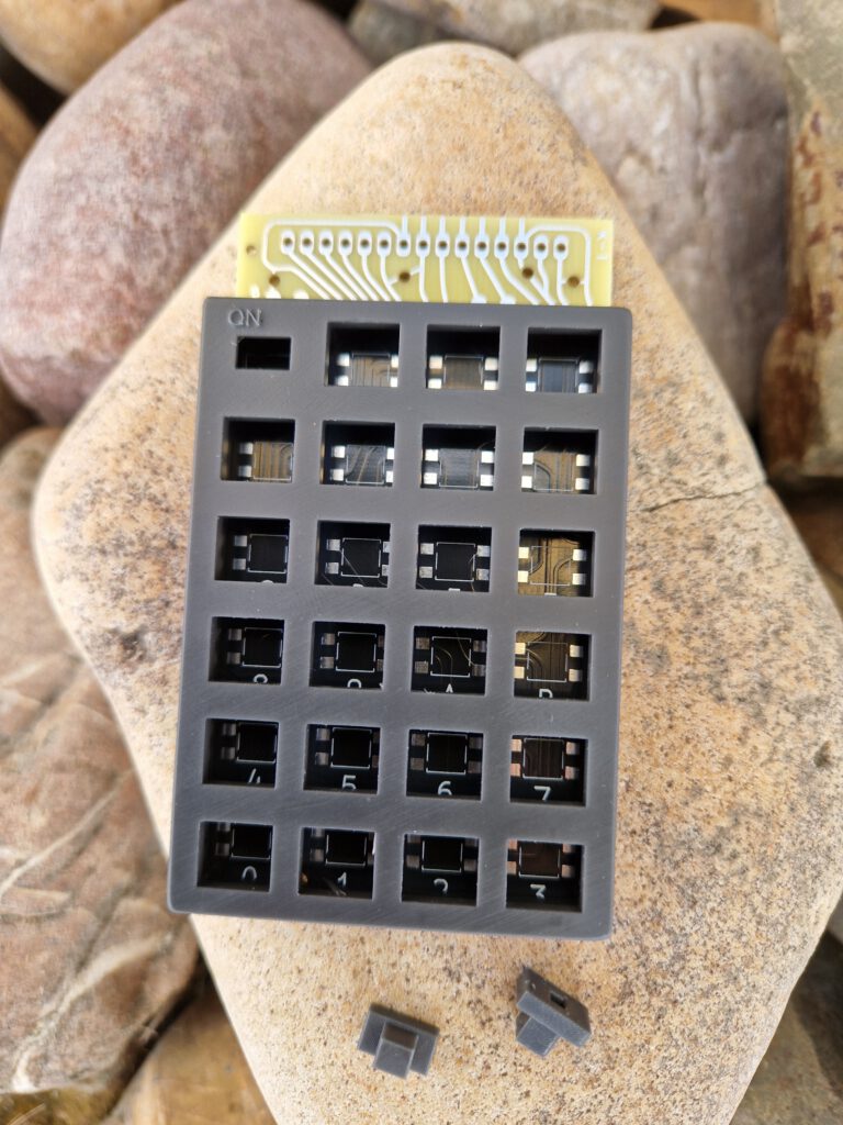
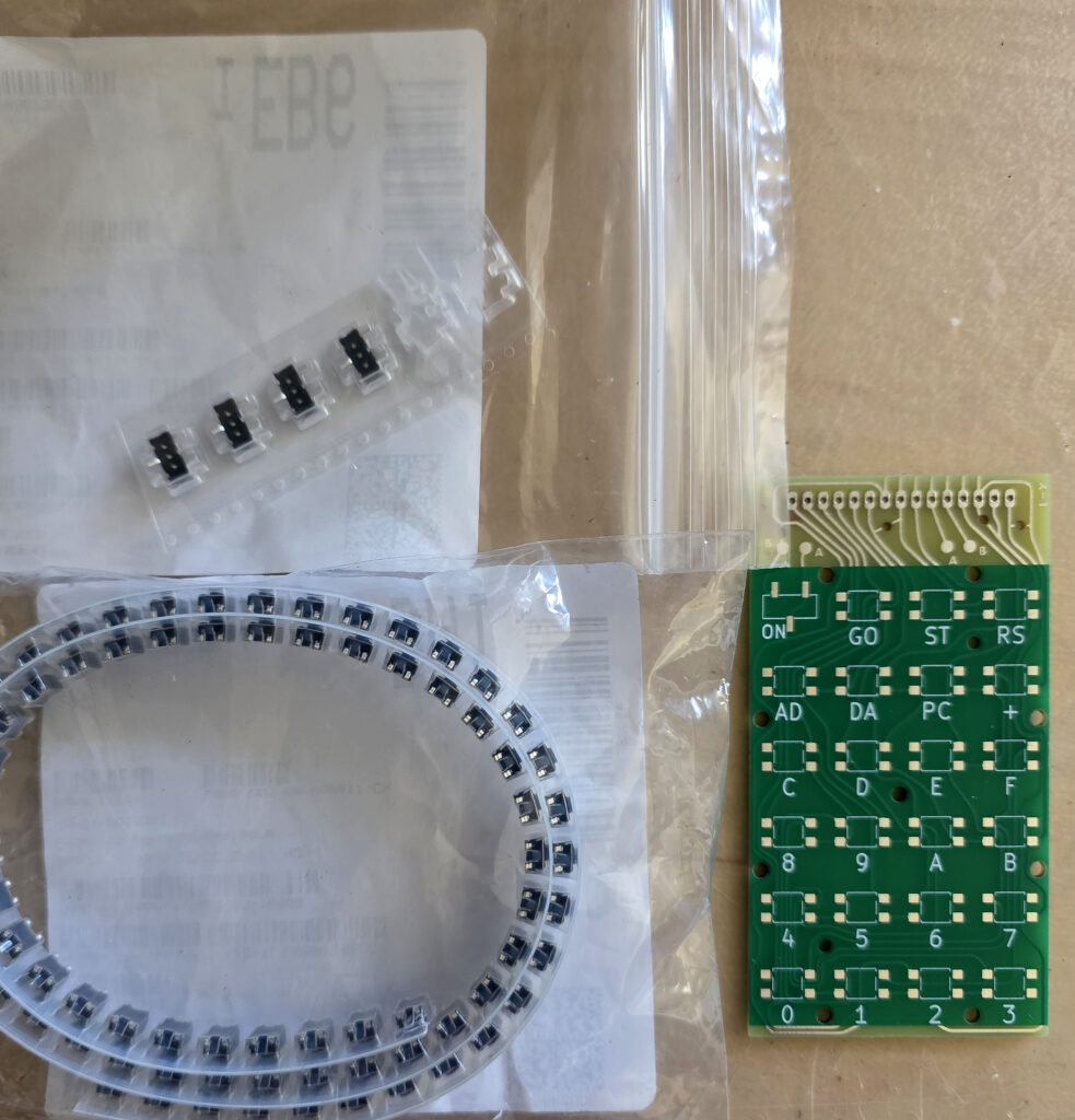 Surface mount switches and slide switch. Solder one leg first of all switches. Check if the switches are nicely in line with the others. Move if required.
Only when you are satisfied with the position of all switches, solder the other legs. Fine tip, not too much solder.
Surface mount switches and slide switch. Solder one leg first of all switches. Check if the switches are nicely in line with the others. Move if required.
Only when you are satisfied with the position of all switches, solder the other legs. Fine tip, not too much solder.
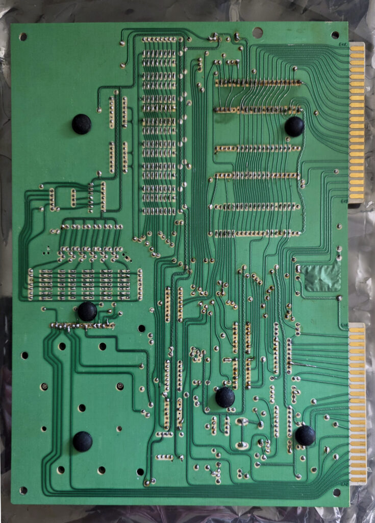
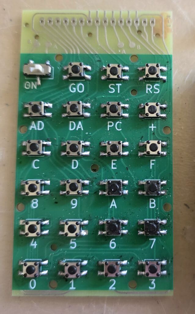 Next solder the two wires (A to A, B to B) on top of the PCB.
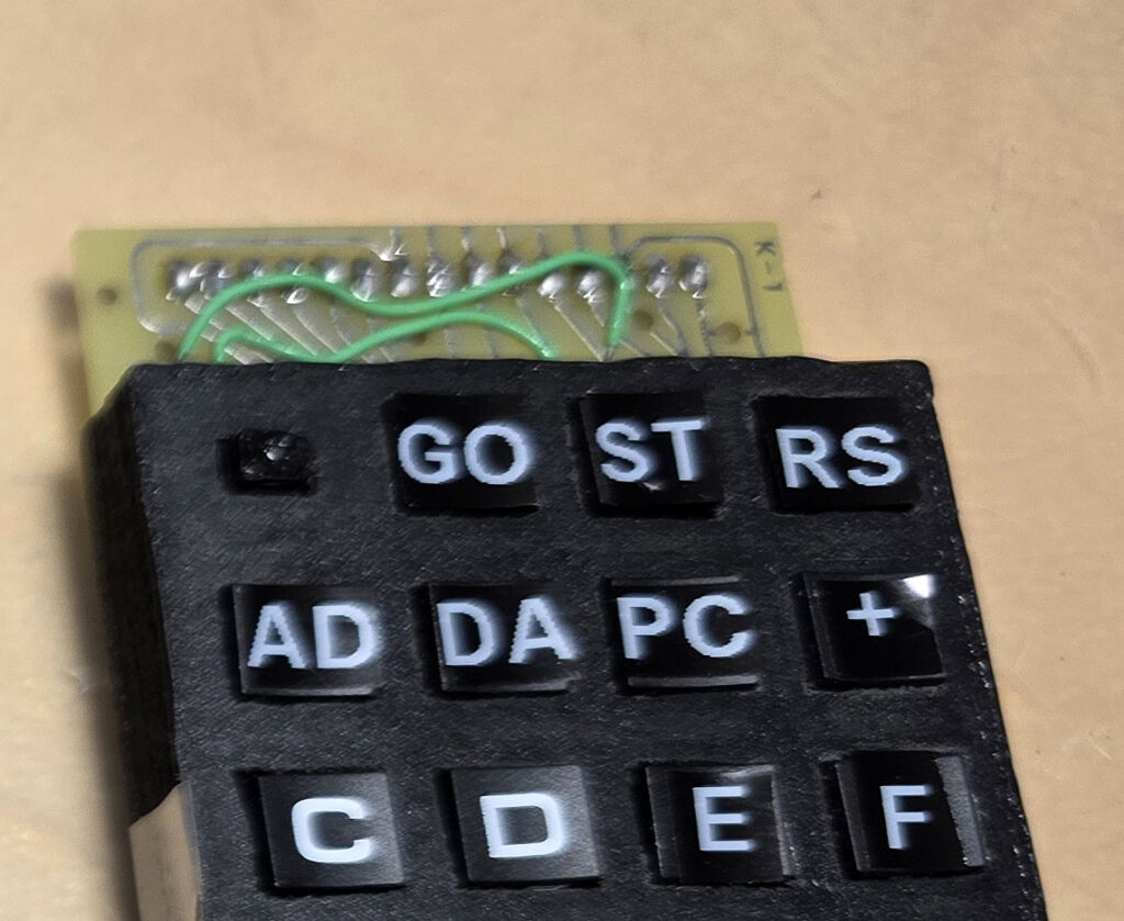
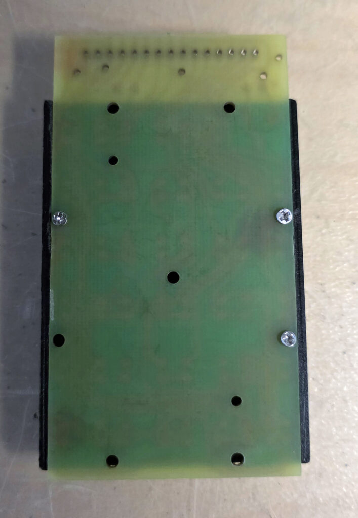
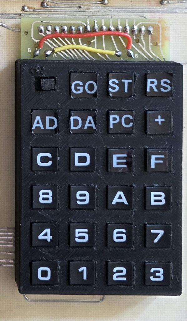
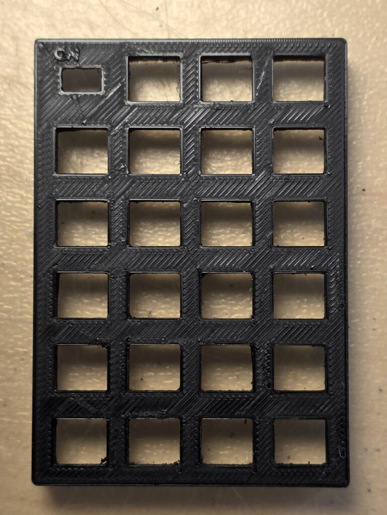
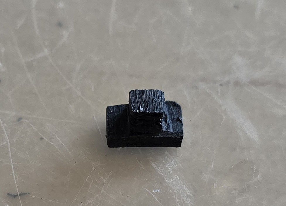 My friend Gerben Voort uses a 3D printing service. In resin black a near perfect result is achieved.
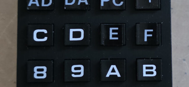
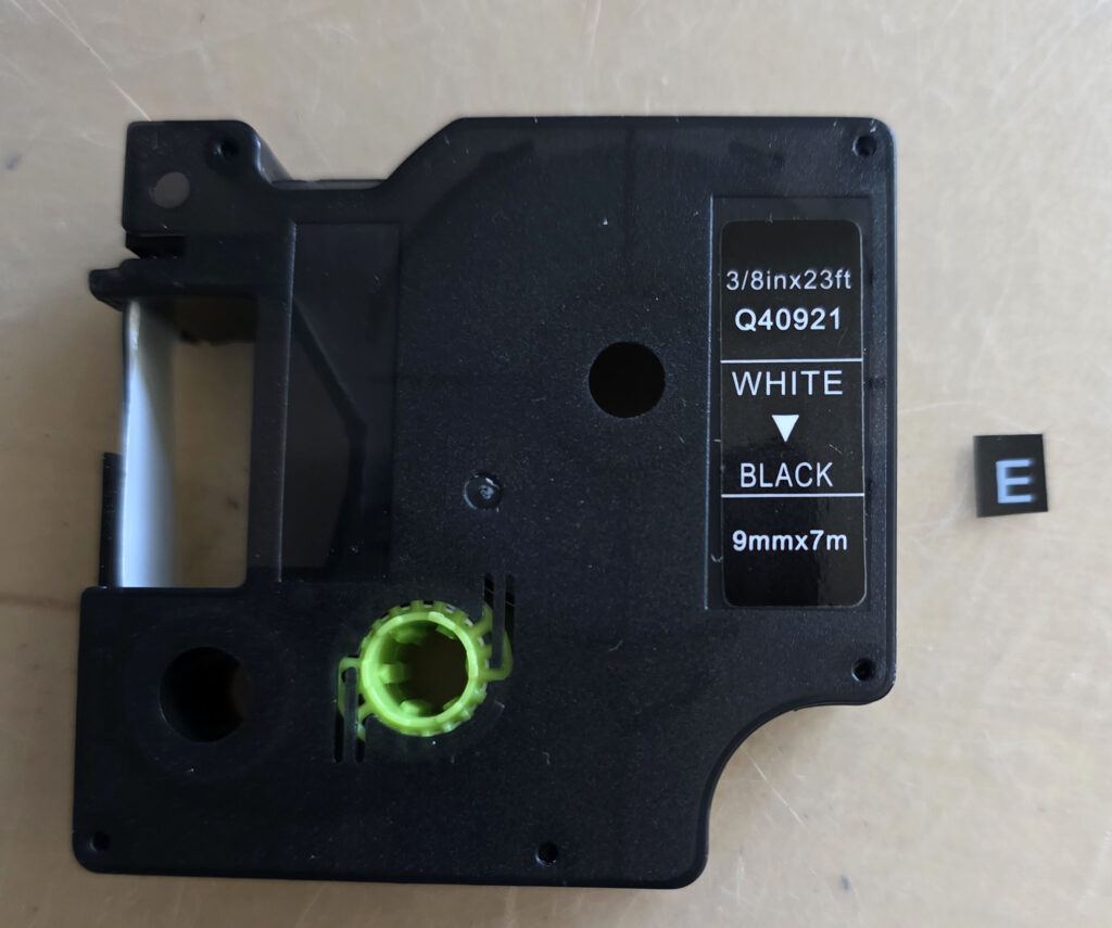
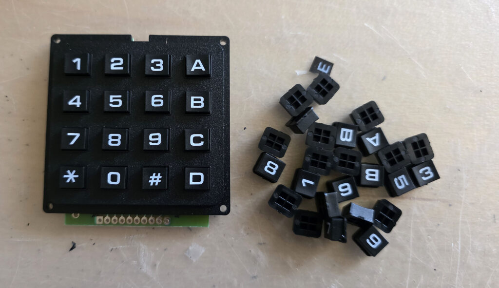 The other keys (E, F, AD, DA, ST, RS, PC, +, GO) need a label. I print those with a cheap Dymo Pocket printer with white on Black 9 mm tape.
The ‘E’ and ‘F’ are printed ‘wide’, the other in normal width.
Cut the label to the right size and put them on the keys.
The other keys (E, F, AD, DA, ST, RS, PC, +, GO) need a label. I print those with a cheap Dymo Pocket printer with white on Black 9 mm tape.
The ‘E’ and ‘F’ are printed ‘wide’, the other in normal width.
Cut the label to the right size and put them on the keys.
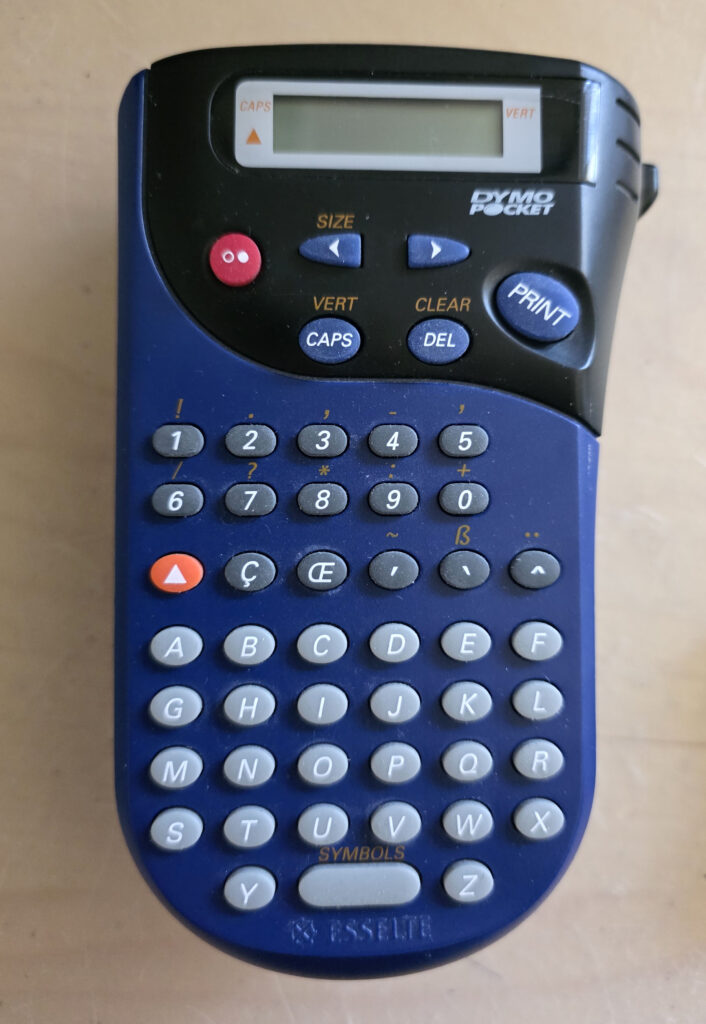 I wish the color white was a bit more white, and the font more like the the other keys, but it is the best I can do with this label printer.
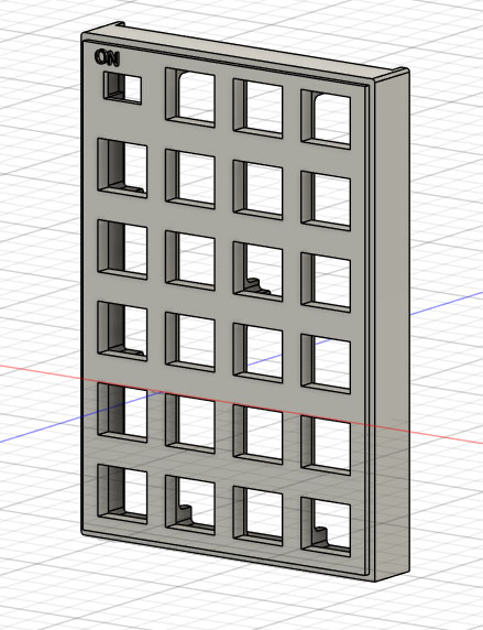
Insert the keys in the frame with the frame top on the table. Put the slide switch button on the slide switch.
I wish the color white was a bit more white, and the font more like the the other keys, but it is the best I can do with this label printer.
Insert the keys in the frame with the frame top on the table. Put the slide switch button on the slide switch.