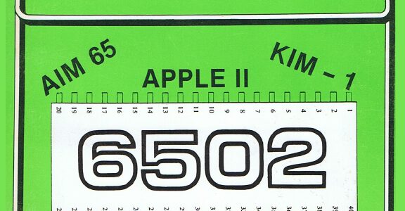
Microsoft’s 6502 BASIC is now Open Source, and that includes KB9 or as it is officially called:
MOS TECH 6502 BASIC V1.1
COPYRIGHT 1977 BY MICROSOFT
Microsoft’s 6502 BASIC is now Open Source
“Now, for the first time, this influential 6502 version is truly yours to explore, modify, and share.”
This means that we are allowed to distribute and modify KB9 and derivates without breaking licenses!
Also see the pagetable post from 2005 that explains a lot about this source.
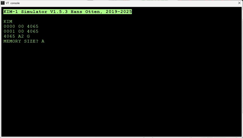
The Easter Egg in KB9:
Answer ‘A’ to the Memory Size Qustion and see this:
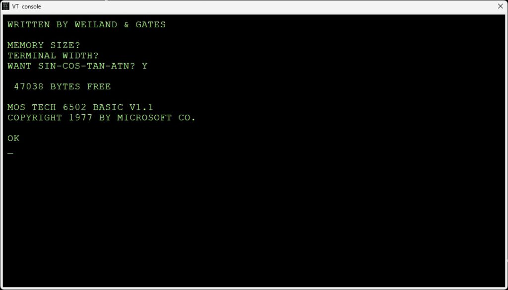
Now we all know about Bill Gates. Ric Weiland is less known. Second Micro-Soft employee. Left 1988, and became a philanthropist, see Wikipedia.
The license that goes with 6502 BASIC is now:
MIT License
Copyright (c) Microsoft Corporation.
Permission is hereby granted, free of charge, to any person obtaining a copy
of this software and associated documentation files (the “Software”), to deal
in the Software without restriction, including without limitation the rights
to use, copy, modify, merge, publish, distribute, sublicense, and/or sell
copies of the Software, and to permit persons to whom the Software is
furnished to do so, subject to the following conditions:
The above copyright notice and this permission notice shall be included in all
copies or substantial portions of the Software.
THE SOFTWARE IS PROVIDED “AS IS”, WITHOUT WARRANTY OF ANY KIND, EXPRESS OR
IMPLIED, INCLUDING BUT NOT LIMITED TO THE WARRANTIES OF MERCHANTABILITY,
FITNESS FOR A PARTICULAR PURPOSE AND NONINFRINGEMENT. IN NO EVENT SHALL THE
AUTHORS OR COPYRIGHT HOLDERS BE LIABLE FOR ANY CLAIM, DAMAGES OR OTHER
LIABILITY, WHETHER IN AN ACTION OF CONTRACT, TORT OR OTHERWISE, ARISING FROM,
OUT OF OR IN CONNECTION WITH THE SOFTWARE OR THE USE OR OTHER DEALINGS IN THE
SOFTWARE


