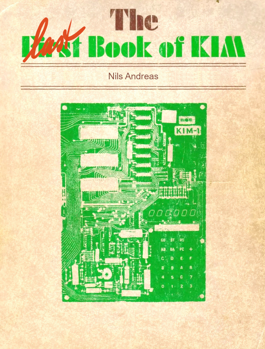
My first computer is a KIM-1. Still have it! A life changing experience!
This is the story of me and the KIM-1.
Philips educational kits.
As a young child, at age 12, I was introduced to electronics with the Philips electronic kits. First a Pionier crystal radio. Easy to build, good instruction manual. Lots of listening pleasure!.
Two years later I bought the Philips EE8 Electronic Engineer kit. Again nice builds (the 8 stands for 8 experiments), with a good manual. Since the manual covered the expansion to the EE20 for 20 experiments, I bought the parts myself one by one at Aurora Vijzelgracht, Amsterdam.
More on the Philips electronic kits.
Radio Bulletin
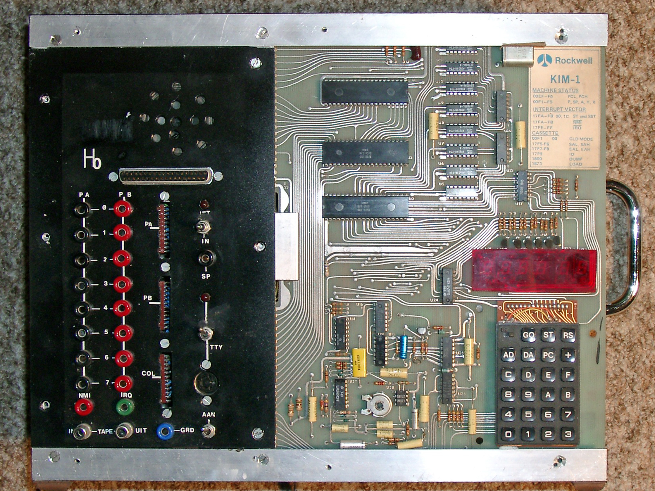
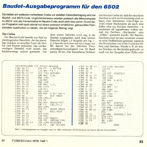
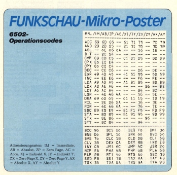
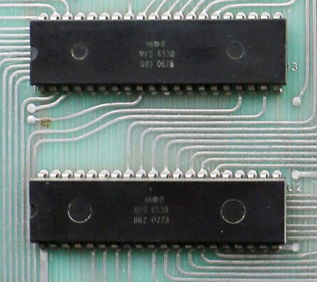
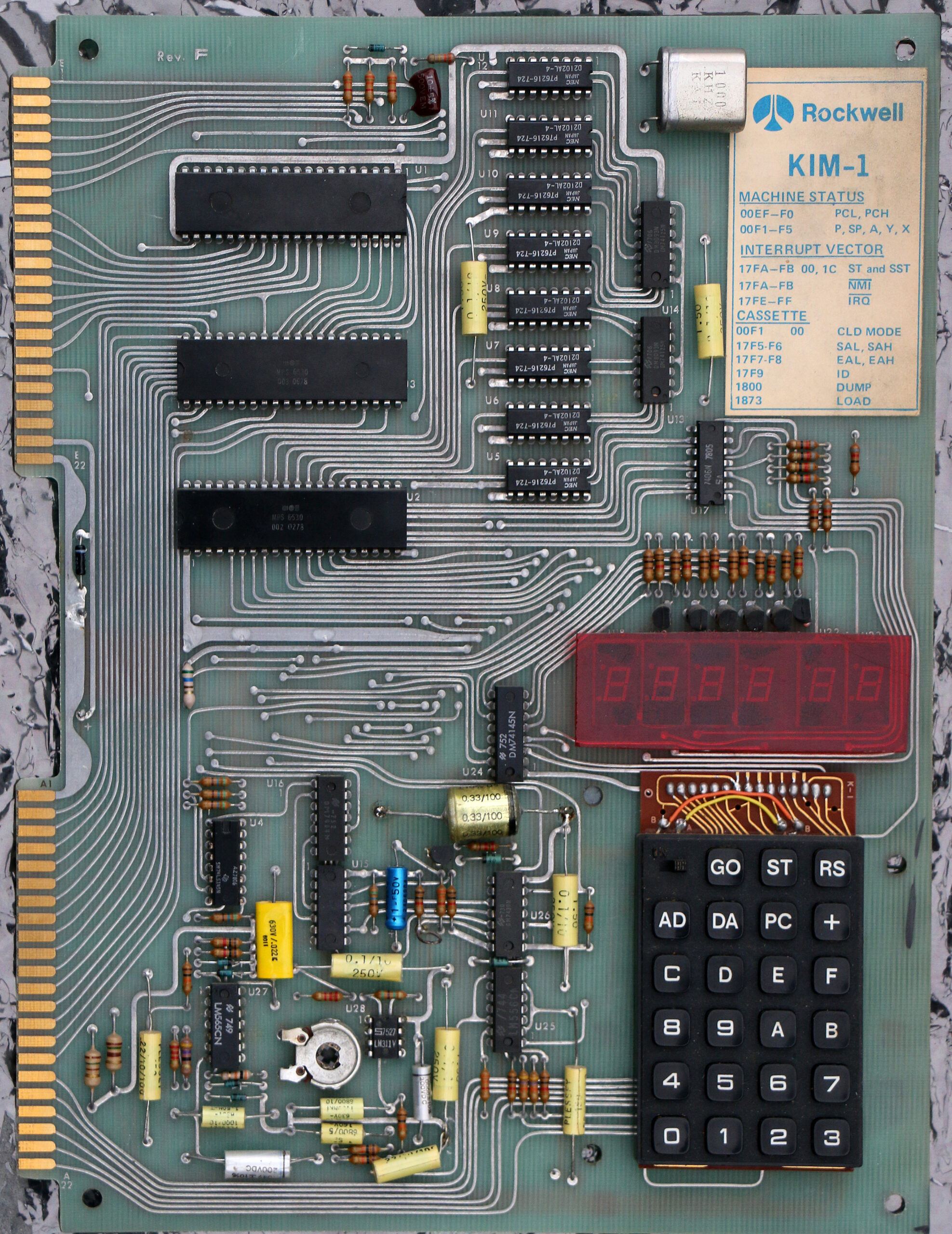
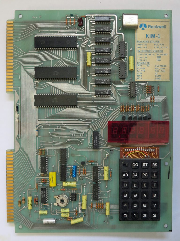
 In 1978 I bought my first computer, a KIM-1. It turned out to be a Rockwell rebadged Rev F Mos Technology board.
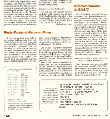
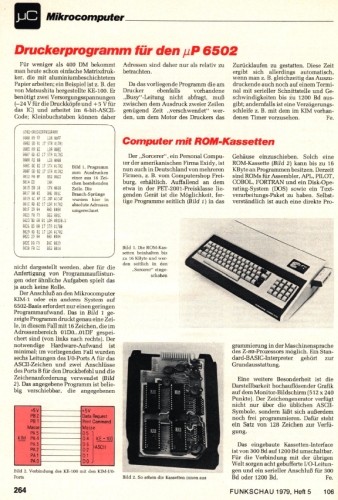
The beginning of lots of fun, learning, member of the KIM gg Club and making and publishing in the Dutch electronics magazine Radio Bulletin and the KIM Kenner.
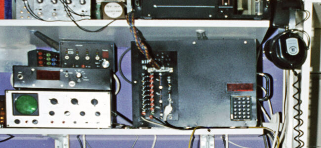
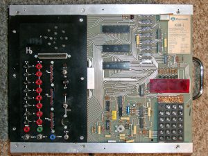
In 2014 the big KIM-1 machine was finally taken down in parts, the following photos showed the end result as in 1985 after many years of tinkering.
The KIM-1 system ended as a real production system in 1985, mainly to write articles, all Radio Bulletin and KIM Club Magazine related work was done with this system.

My KIM-1 workplace in 1979, no video terminal, no printer, hand assembly

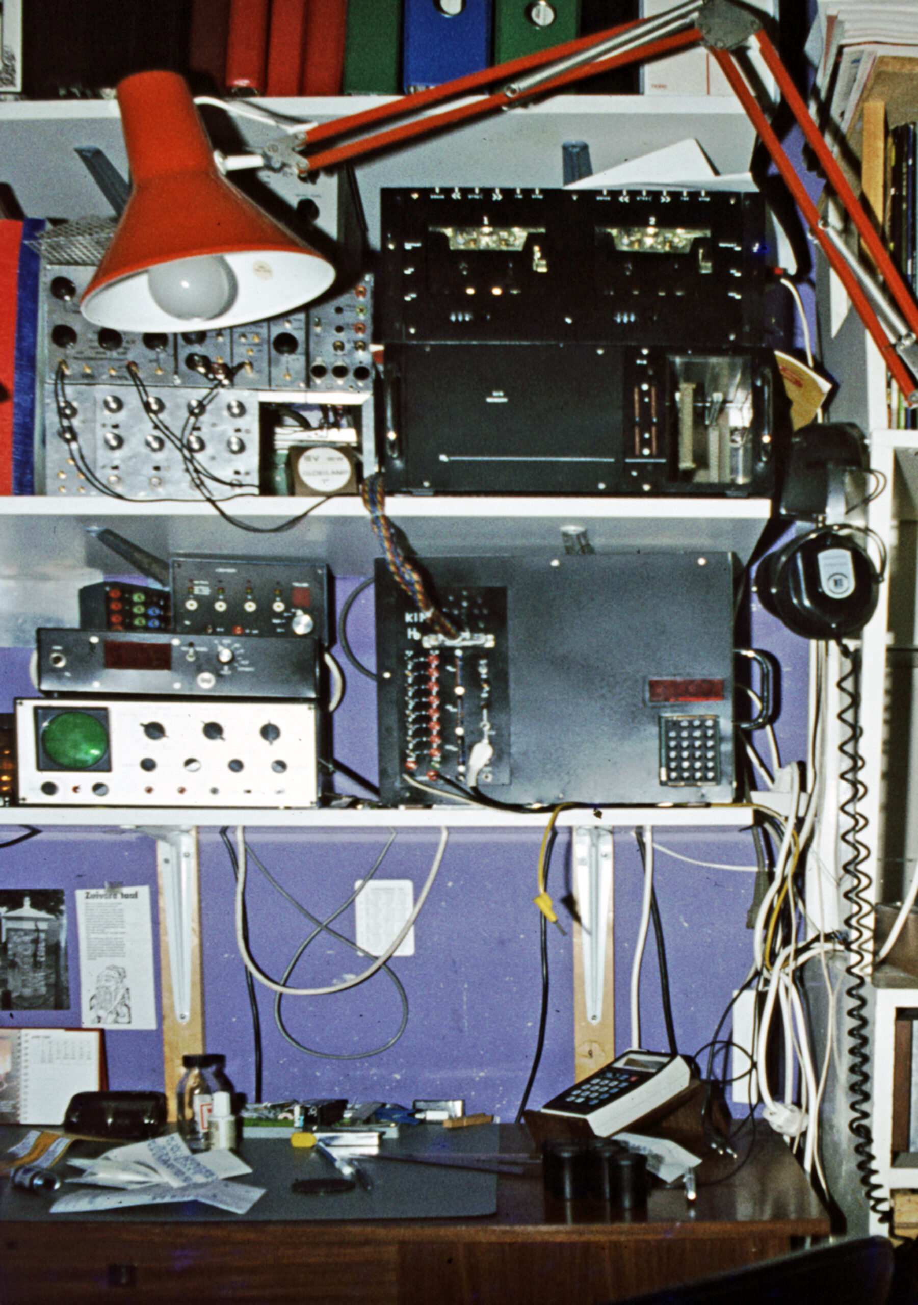
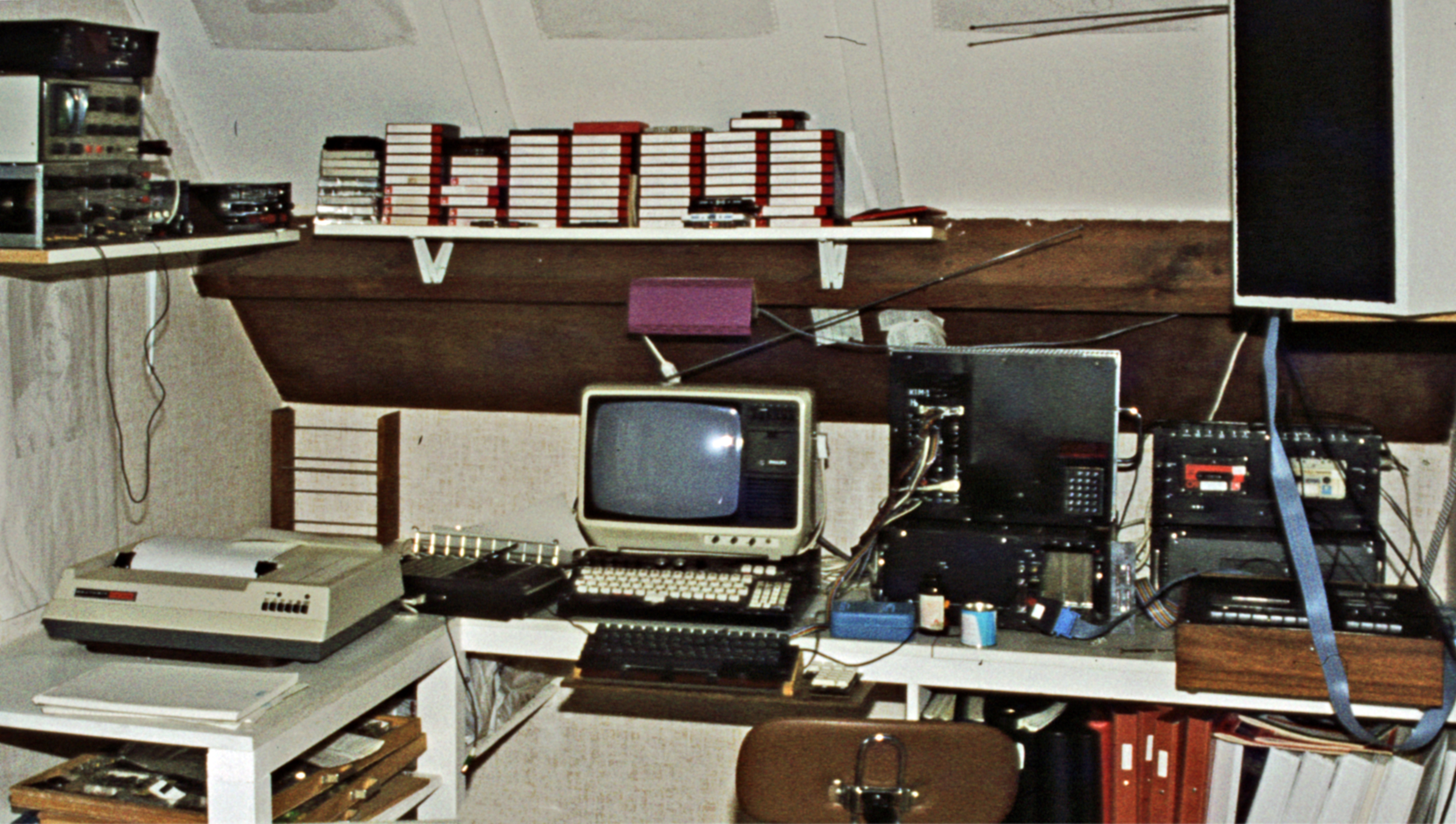
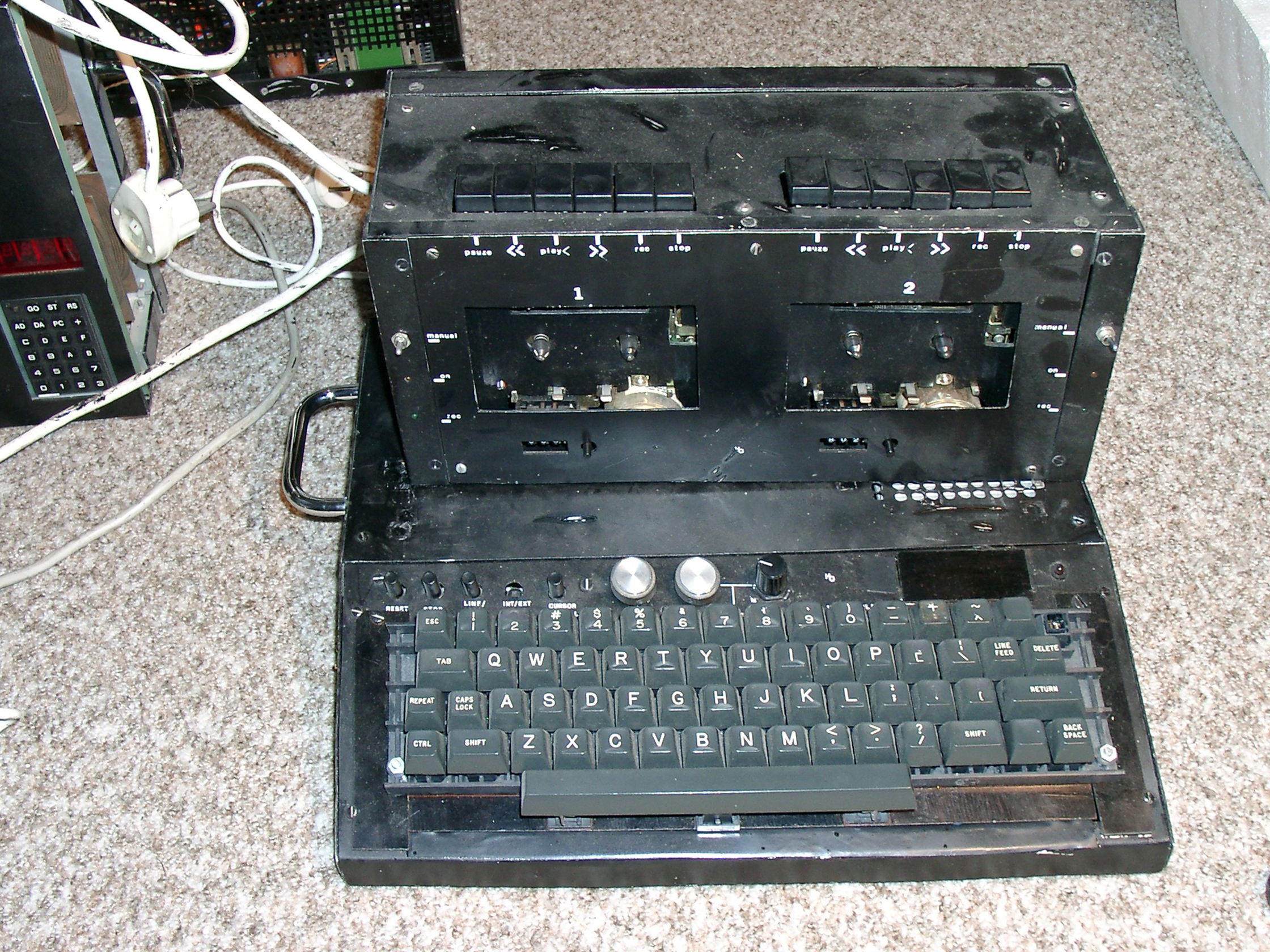
My workplace setup in 1982: KIM-1, dual cassette, tv monitor, H14 printer, ASCII keyboard

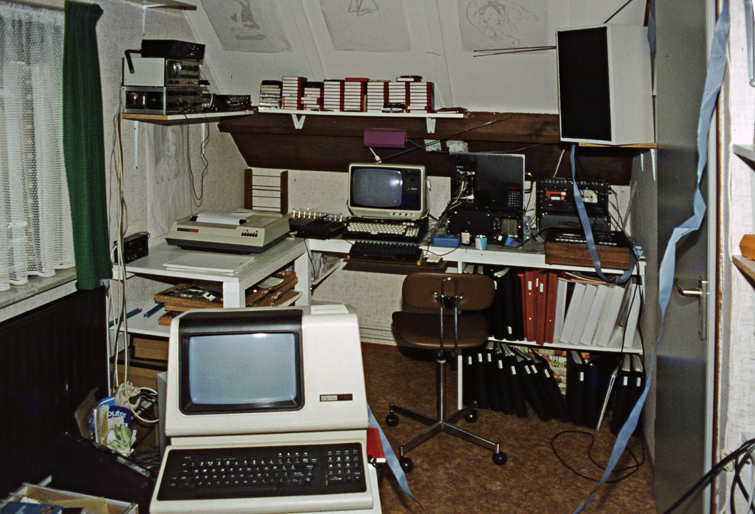
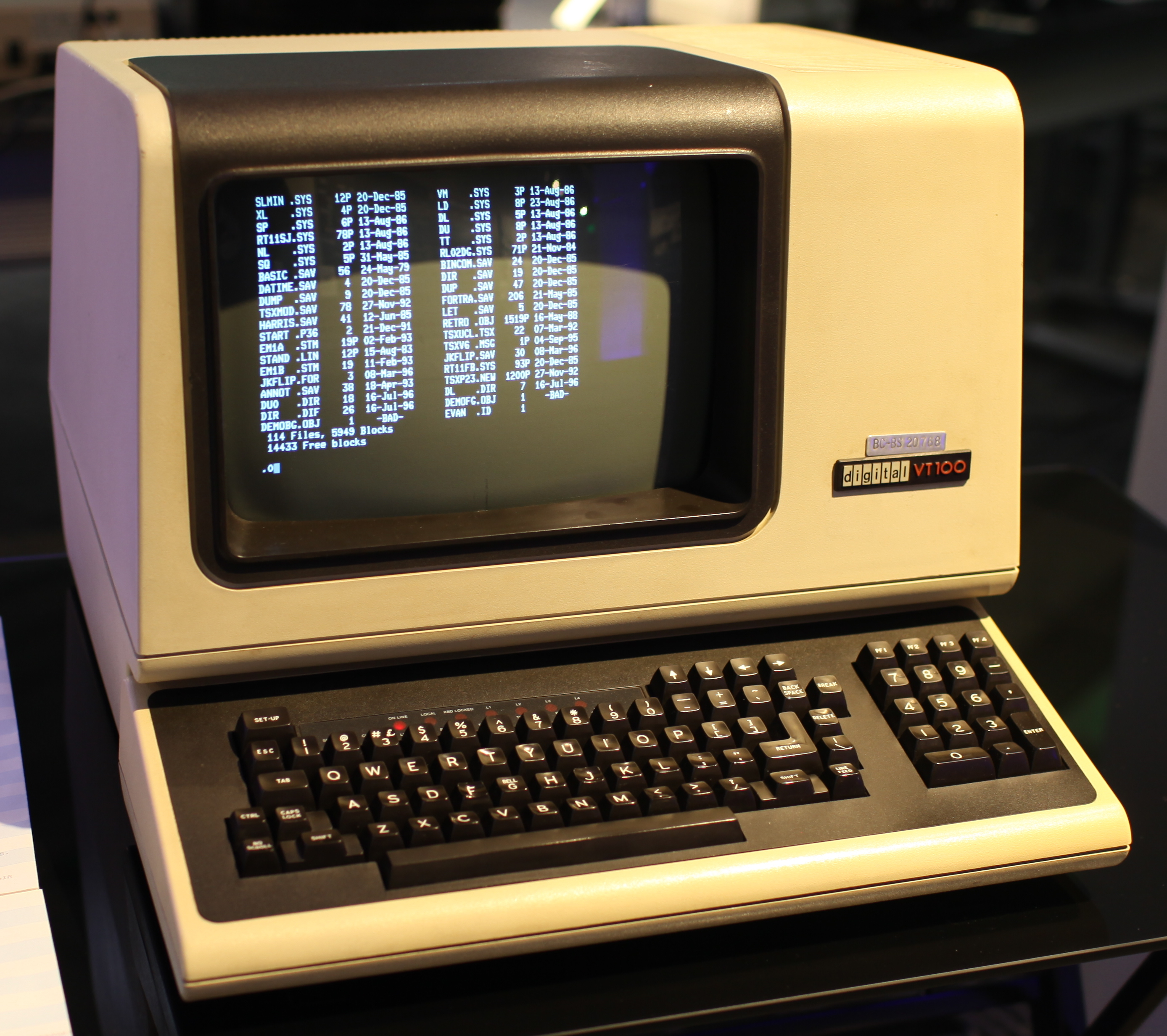
1984, VT100 as videoterminal, what a progress!
Then a CP/M machine took over (a Spectravideo X’Press 738) with the same VT100 as terminal.
- KIM-1
- 8K RAM in system case
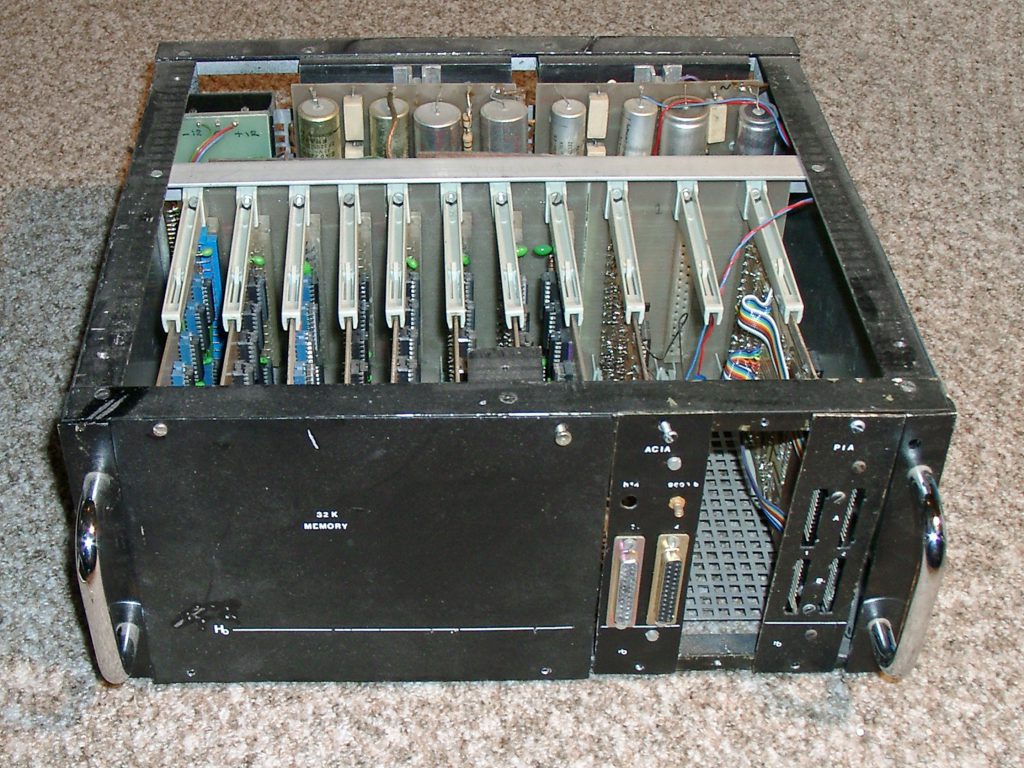
- 32K RAM in expansion case
- Two ACIA 6850 serial
- A PIA/VIA card with two 6820 PIA’s
- Parallel ASCII keyboard with home made logic circuit
- Video Display 32×32 uppercase characters on an analog TV
- Dual cassette tape system with motor control
- MDCR digtal cassette system in second expansion case
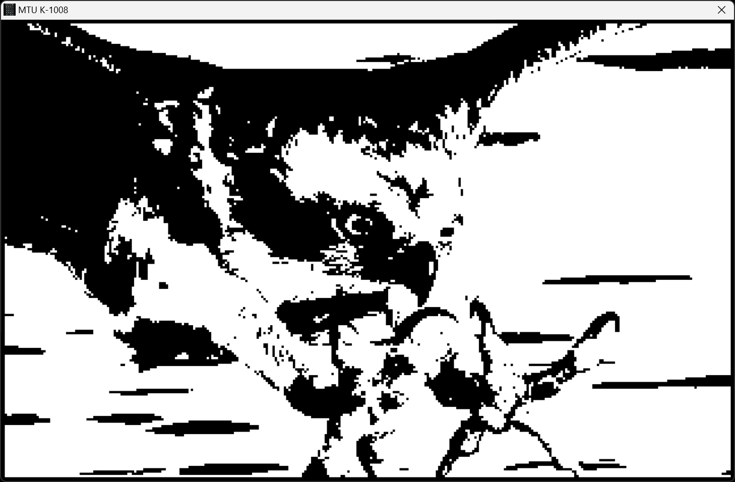
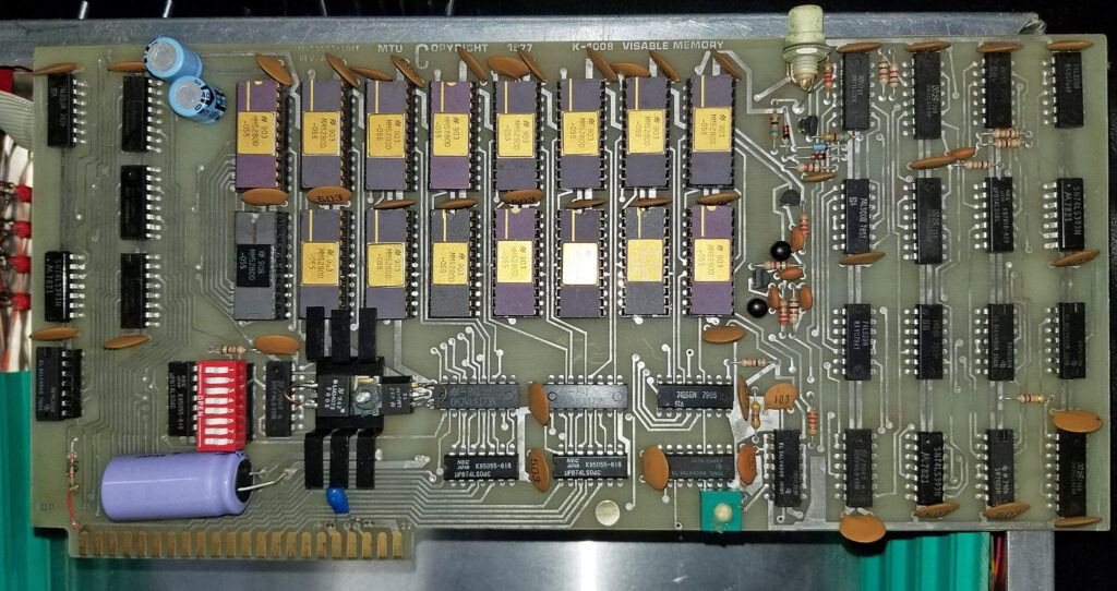
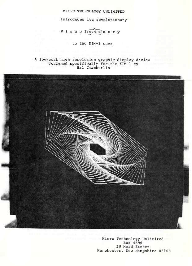
- Radio Grafisch Display in second expansion case
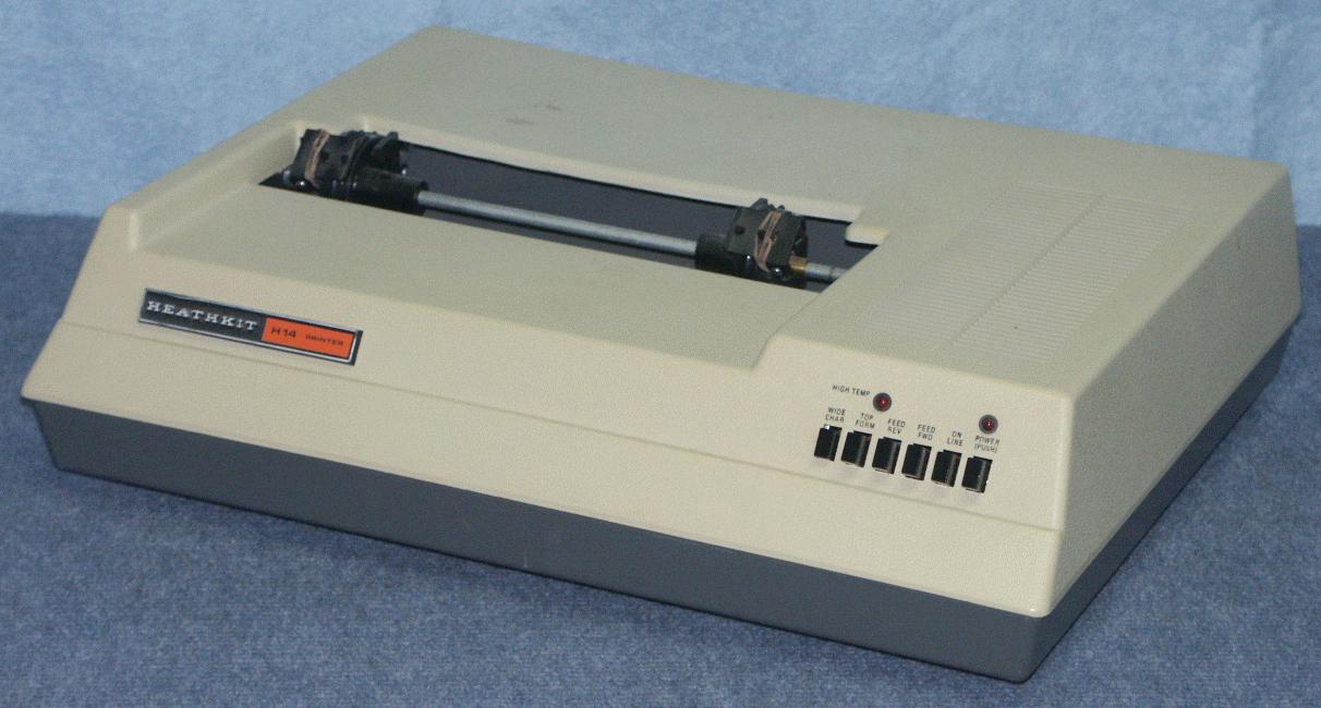
- Heathkit H14 matrix pinter, serial with RTS handshake via bitbanging RIOT port
- VT100 Digital Equipment Video display unit VT100
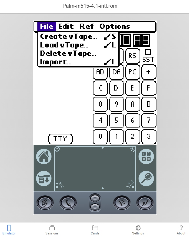
- Boot tape to load device drivers and Micro Ade (extended to 8K)
- MICRO ADE assembler/editor, used for program development and article authoring
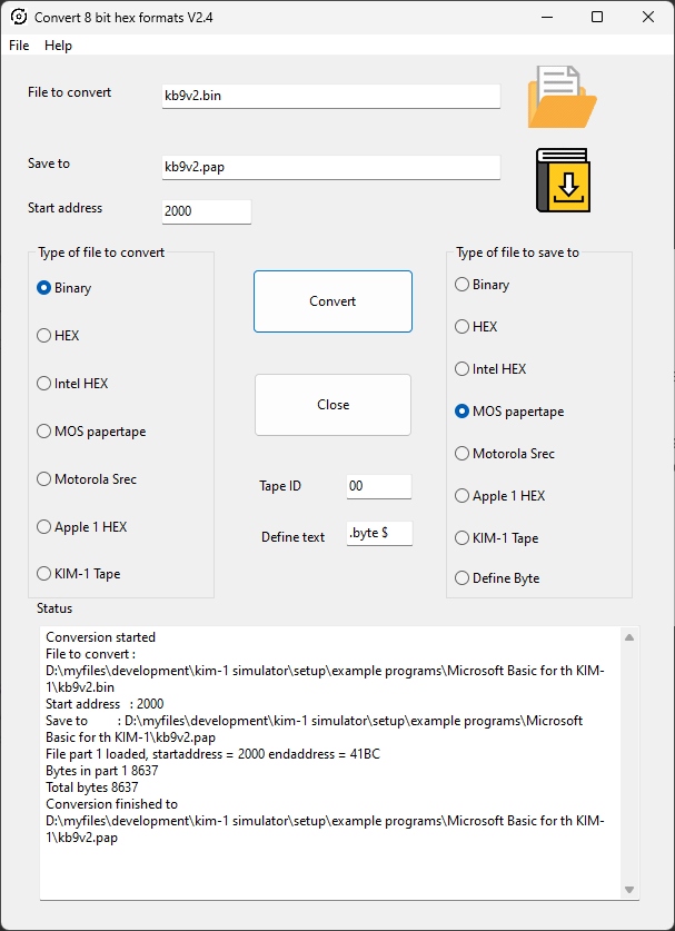
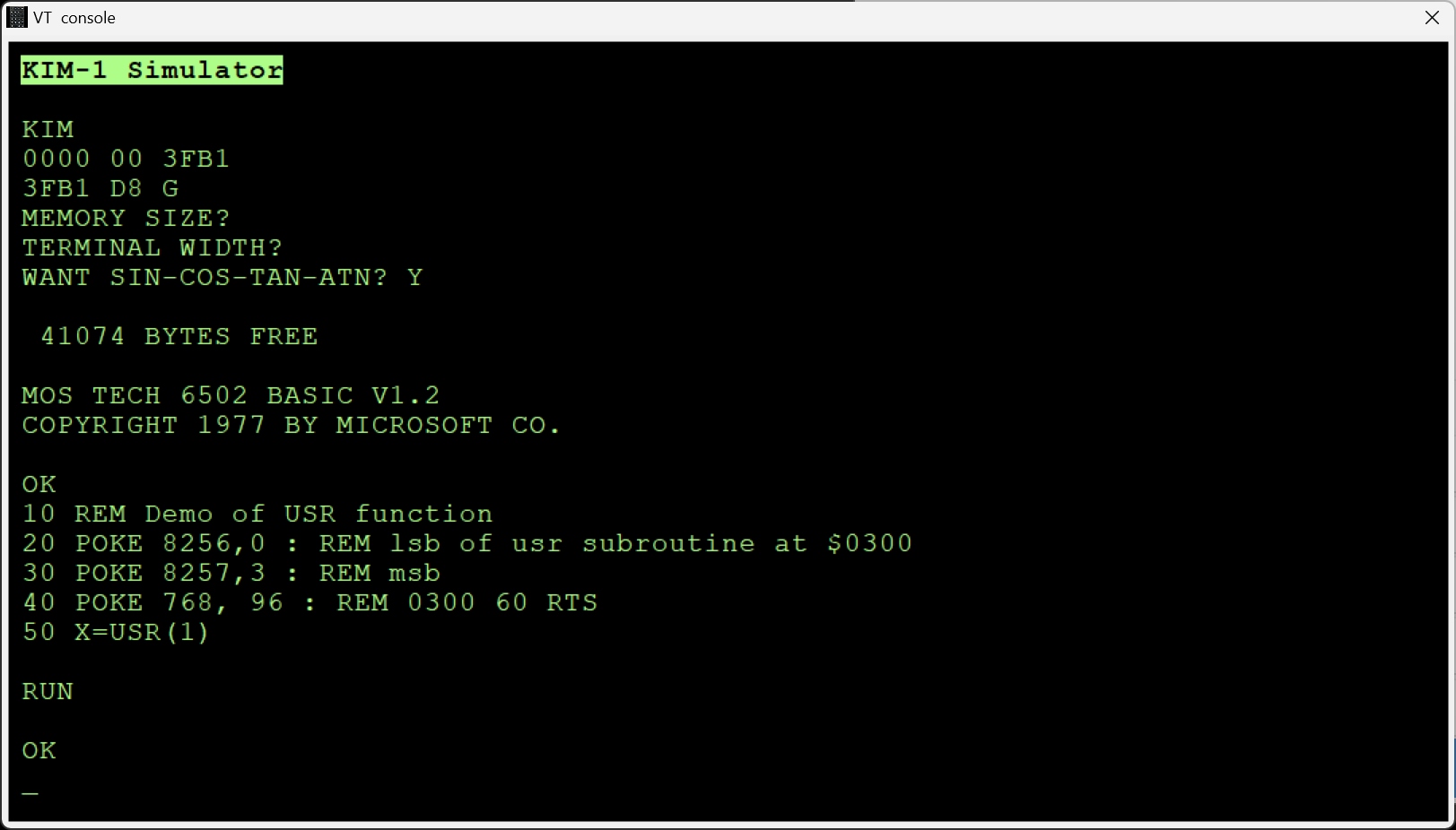
- Microsoft Basic KB9 (not used often, nice study material!)
- Pascal-M compiler and interpreter (mainly development and experiments, not for production)
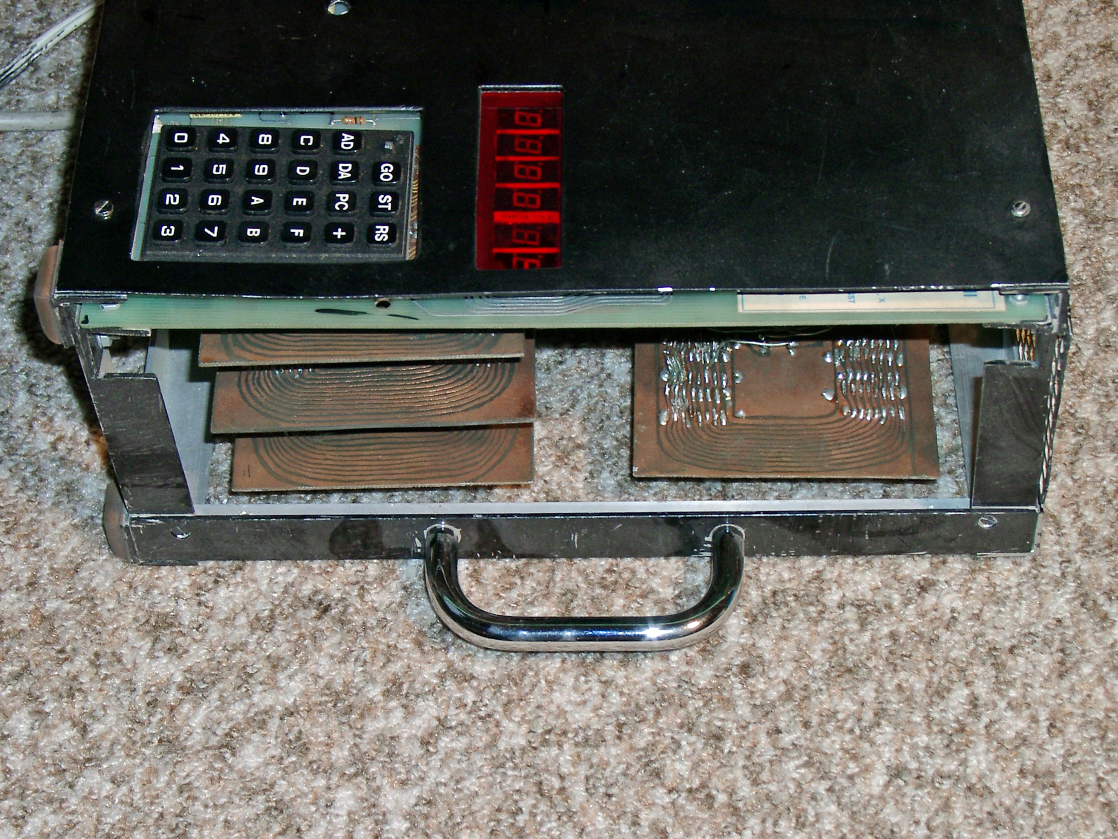
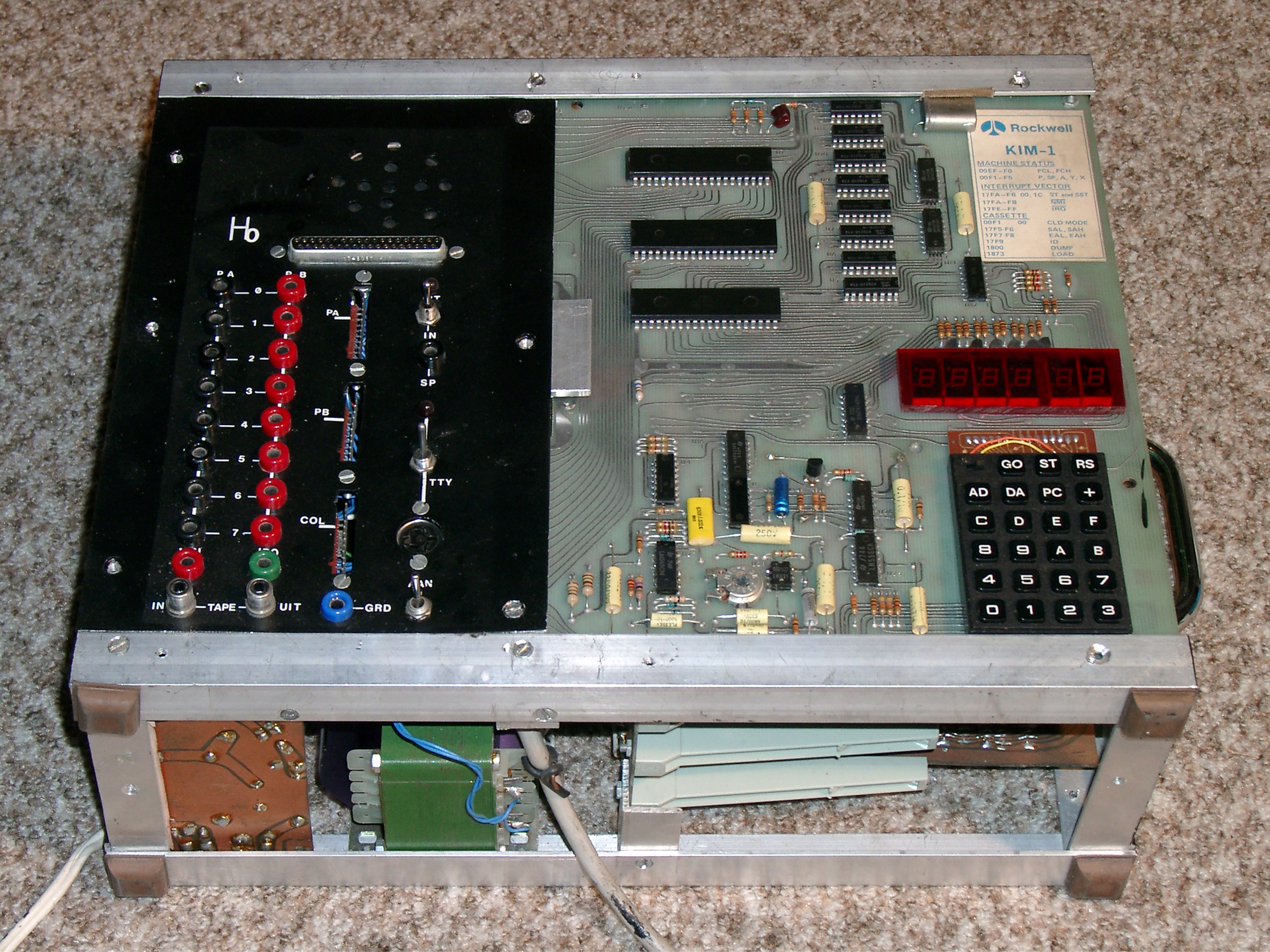
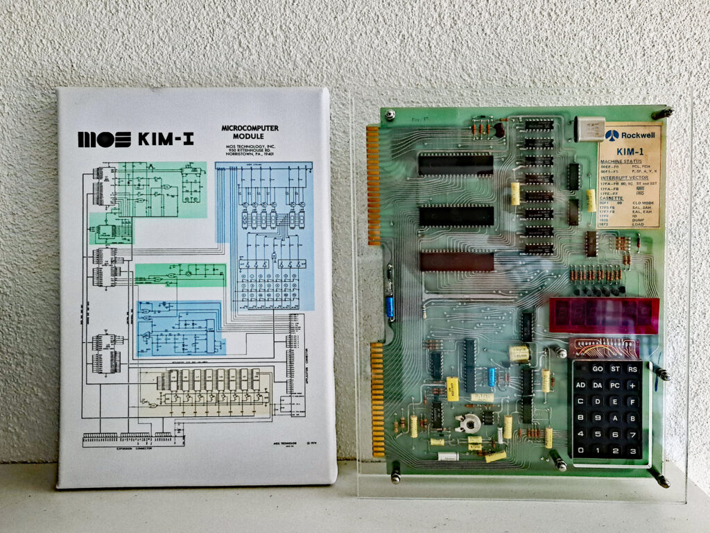 First the KIM-1, I still have it, in working condition, in my private museum. Changes still visible, a red acryl cover over the LED displays, a capacitor moved to the back to make it flat enough to fit the case I made and some supports to have it lay stable and safe on a table.

Why a KIM-1?
In 1977 I was reading in the electronics magazines about the revolution taking place: 8 bit microprocessors!
During my study I encountered Digital Equipment machines, PDP-8 in the lab, PDP-11 in the Mathematic Computer Science department, a Minc in Medical Physics group, my major.
The electronics department where I was doing an intern not only introduced to digital electronics and I helped them to introduce the Z80 to the instruments designed for laboratory experiments.
I learned assembler quickly, PDP-11 was a dream come true, the Z80 a bit of a nightmare but you could do so much with effort.
At the same time I started to write for the magazine Radio Bulletin, simple analog and digital circuits and continued to be an editor until 1987. I met Dick de Boer who was writing his famous Microprocessor articles and introduced the KIM-1 to the Dutch electronic engineers. So a KIM-1 with the very attractive 6502 was the logical choice for my first microprocessor system.
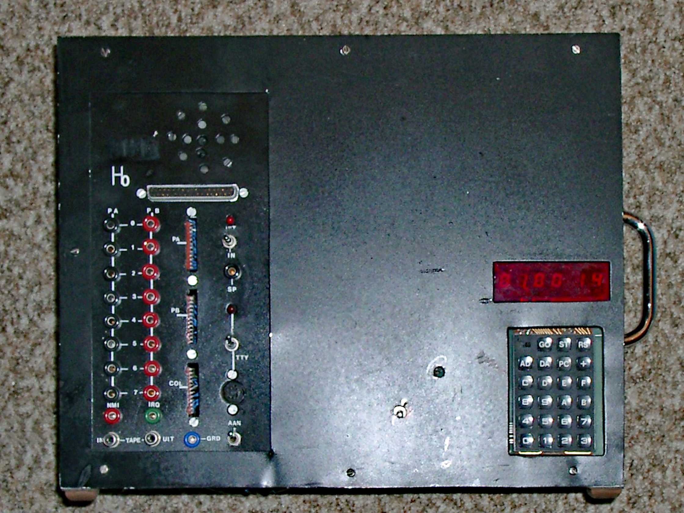
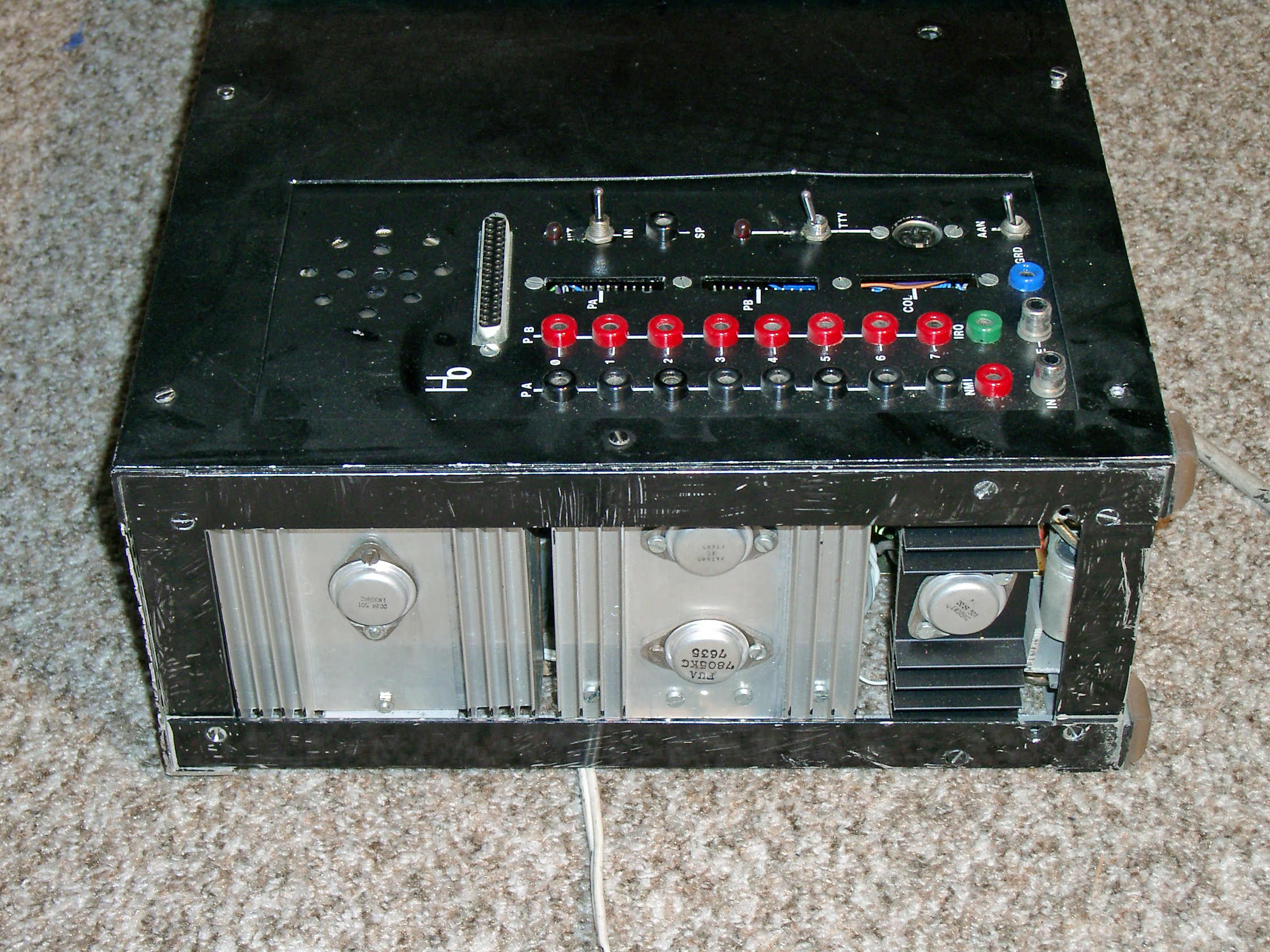
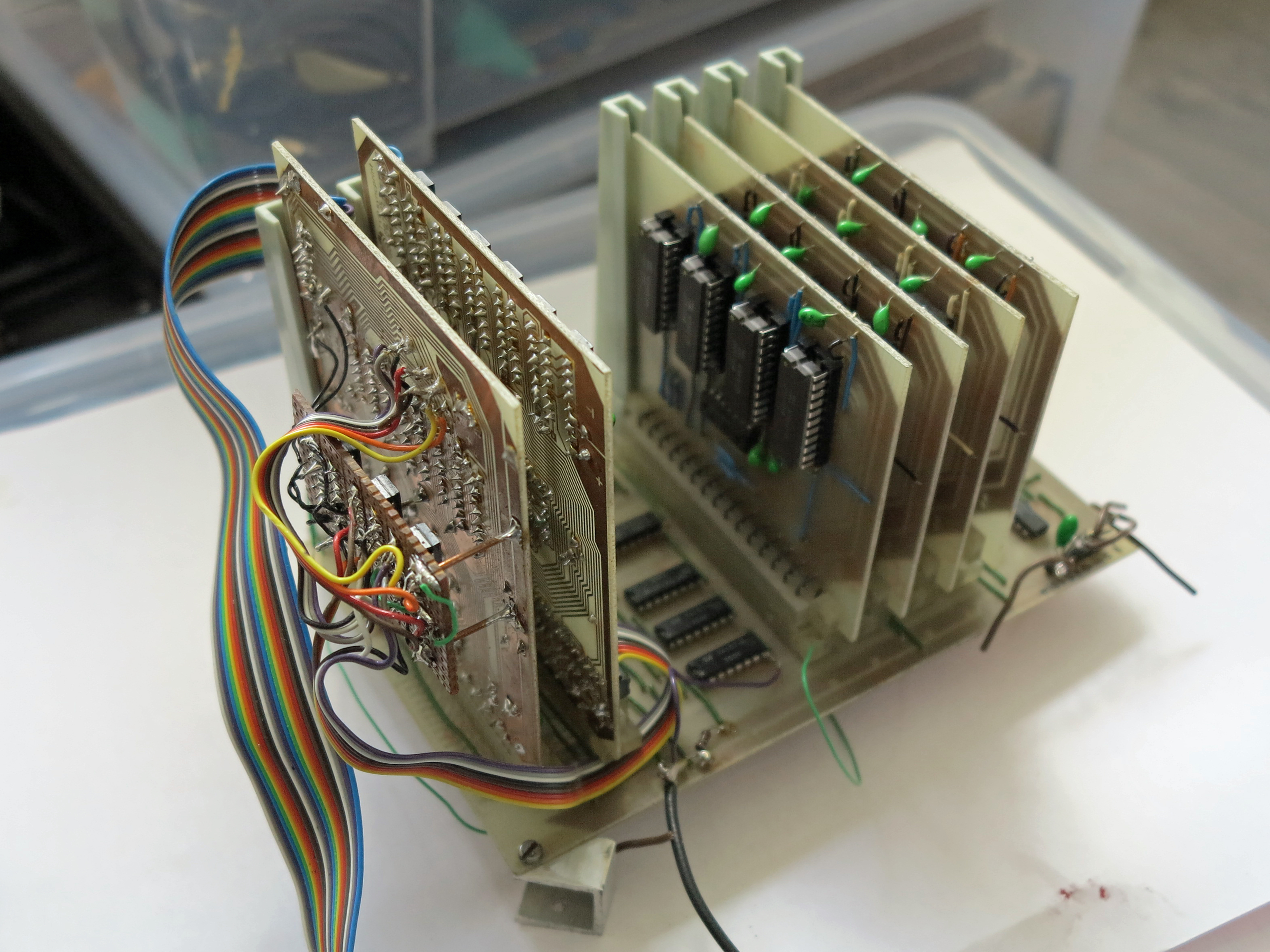
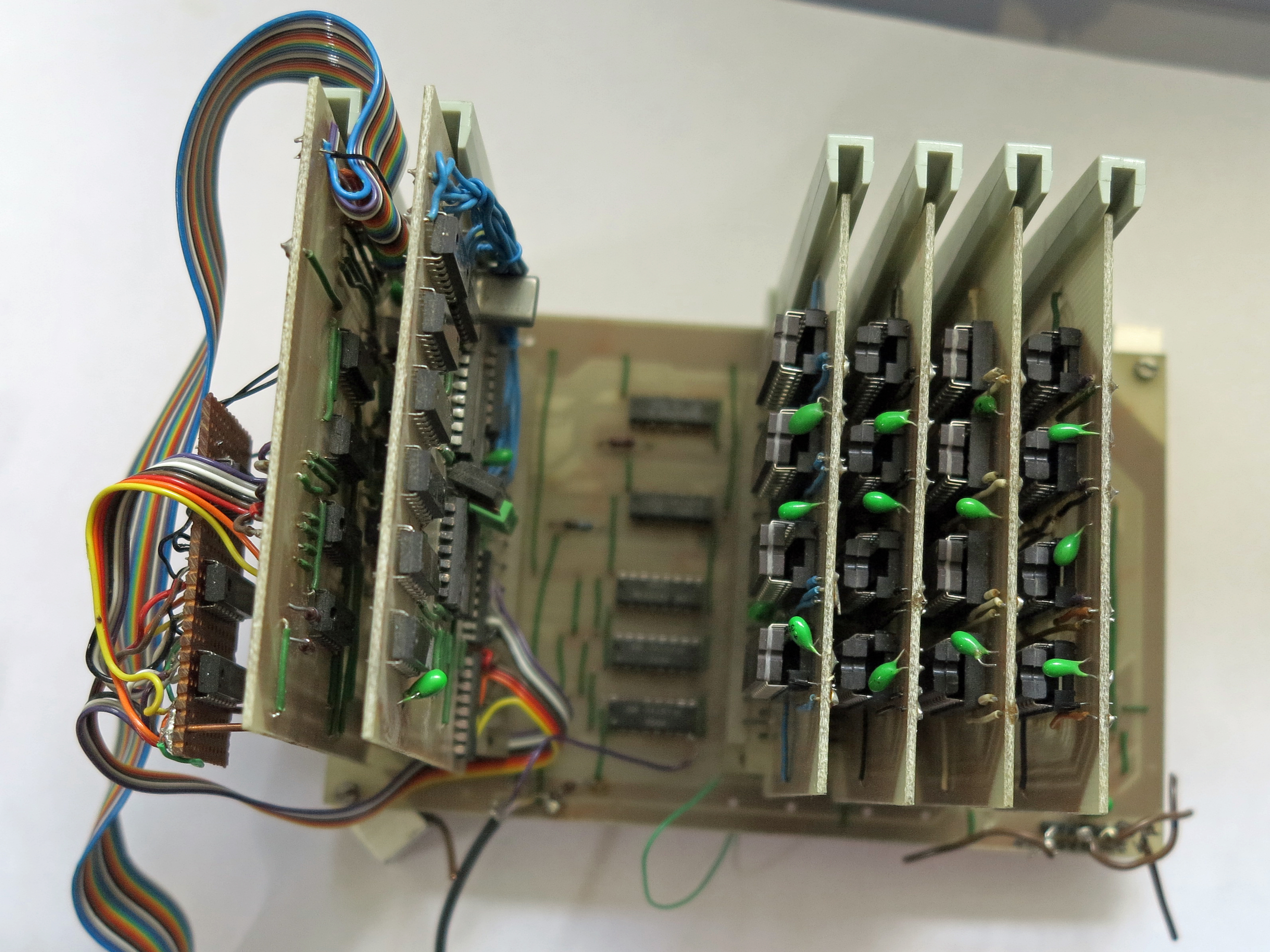
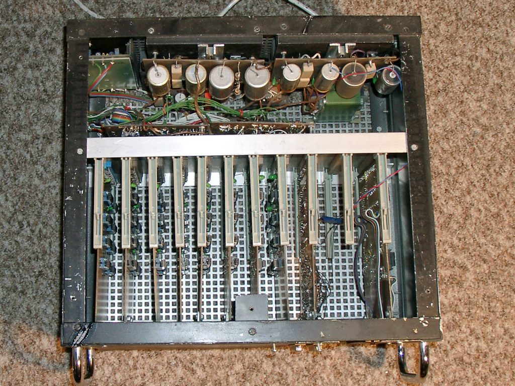
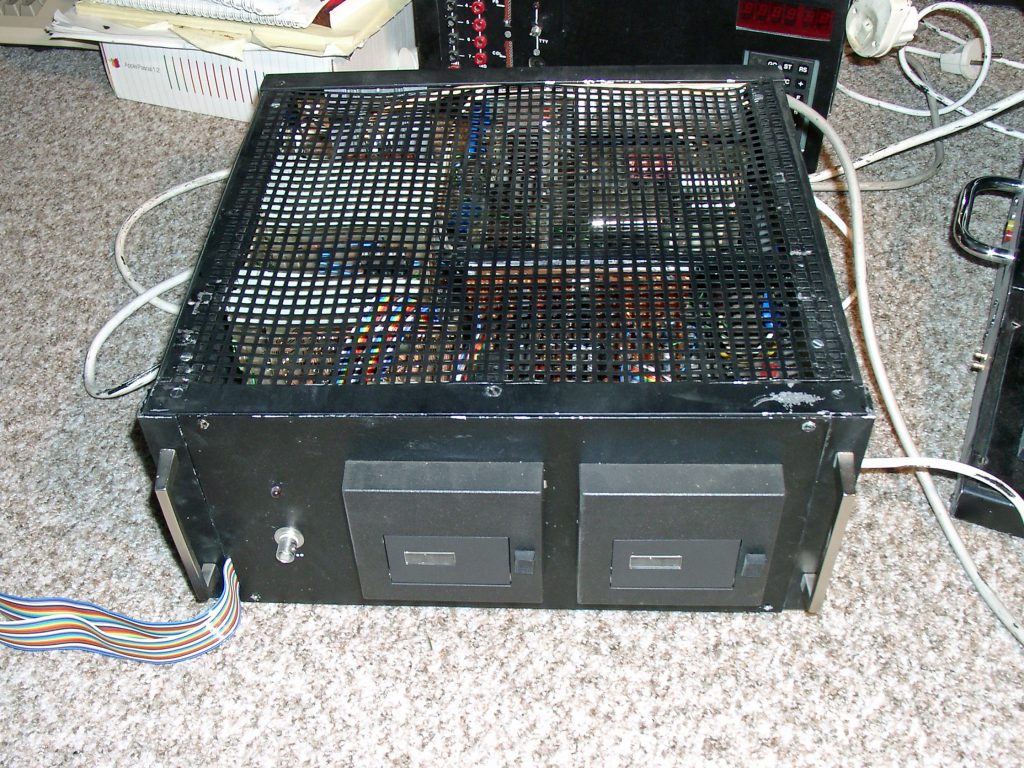
First case: memory, connectors, power supply
A KIM-1 itself was fun to learn with, but it quickly needed more; a permanent power supply, protection, easy to access connectors and interfaces for a bus to have more memory.
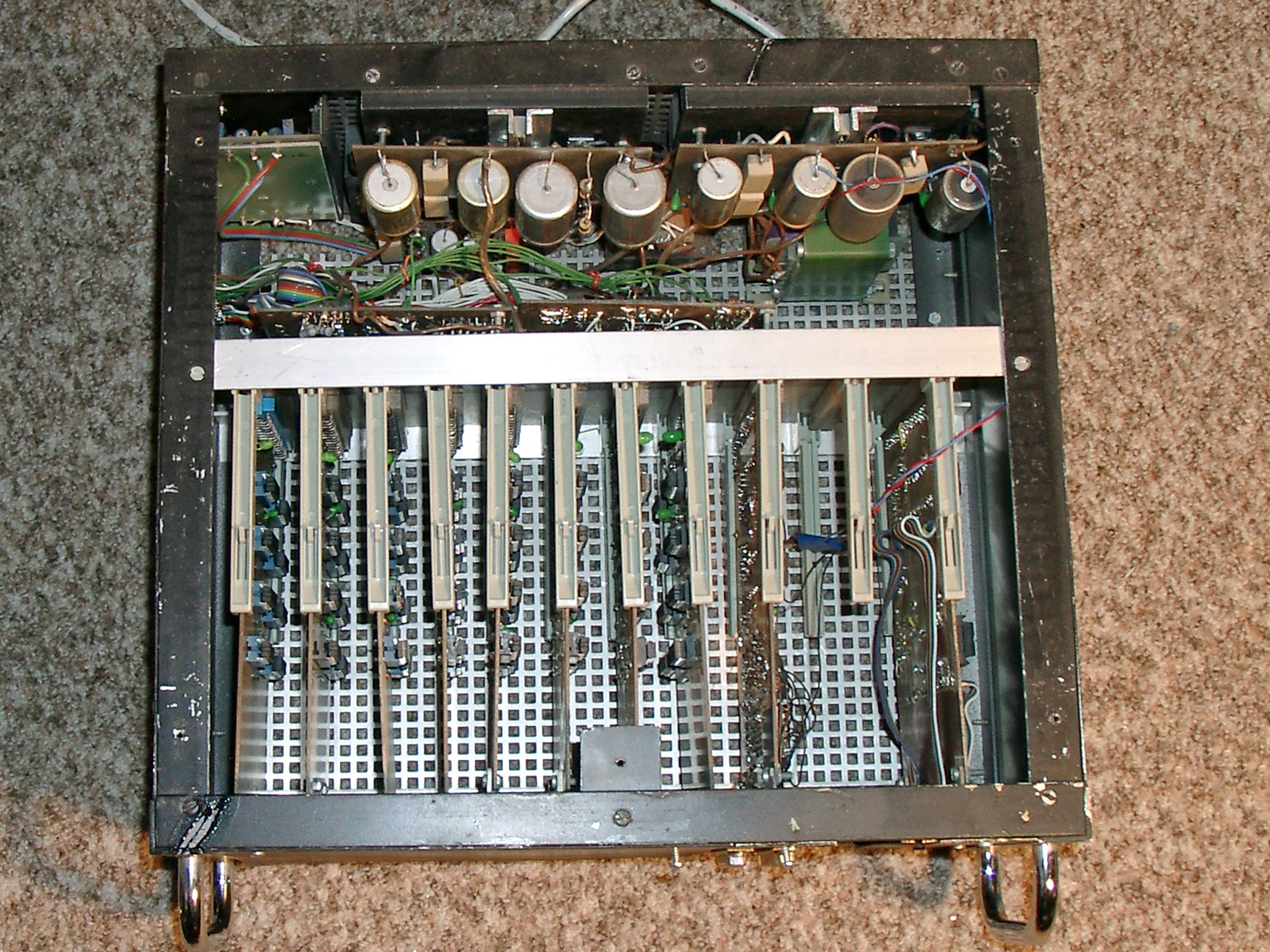
So the case seen in the next figure was built:

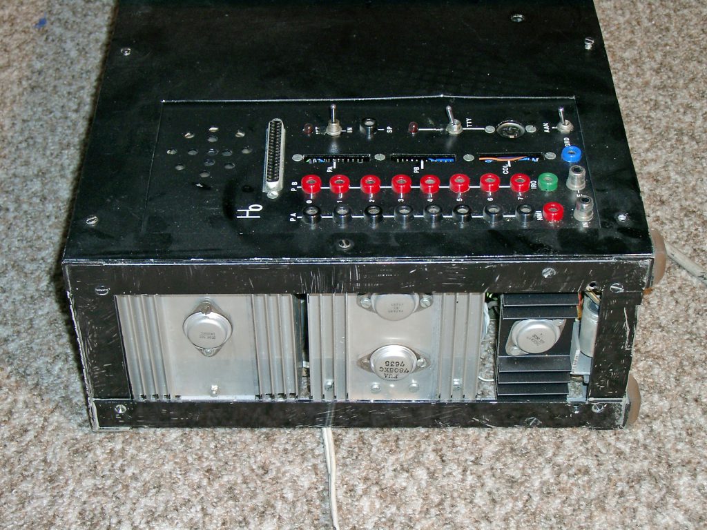
Power hungry, so lots of lineair power supplies with large cooling.
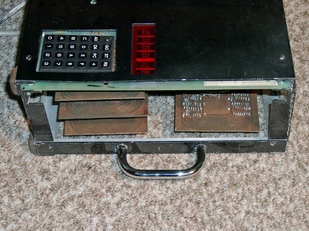
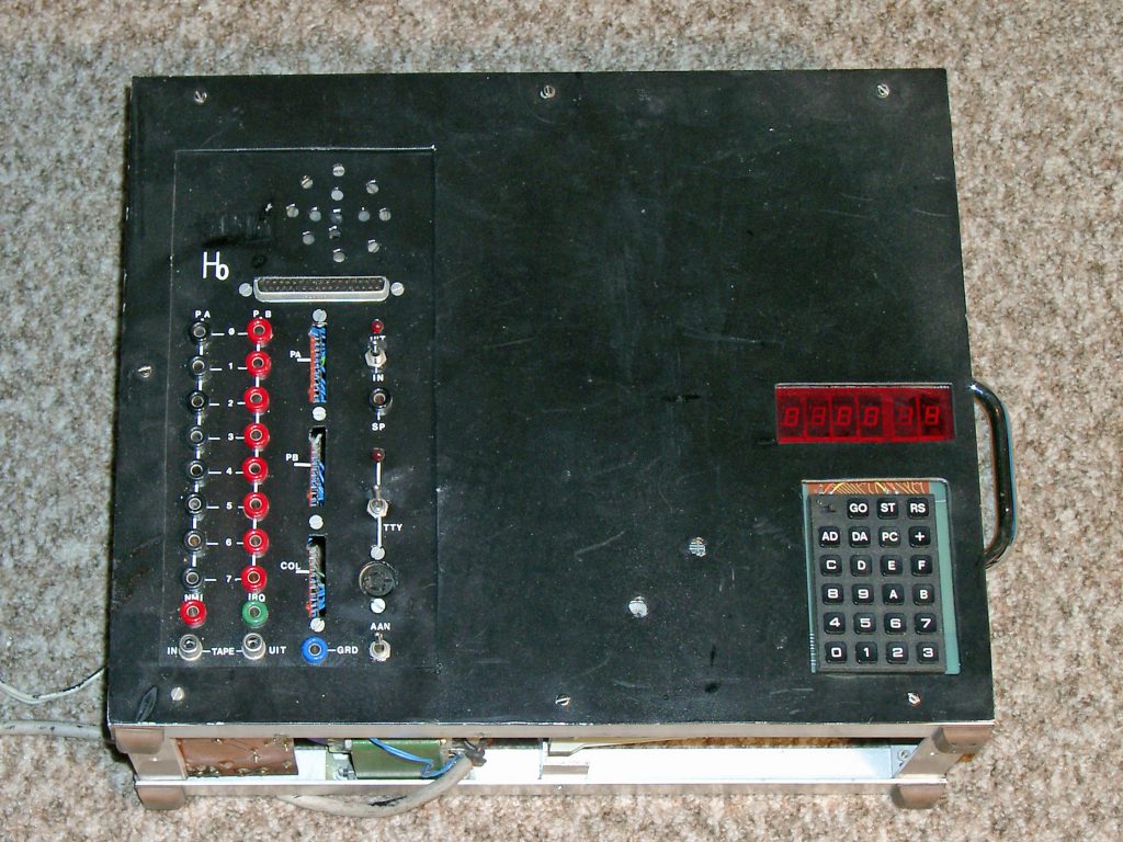


The first case I built from alu profiles contained the KIM-1, a backplane for 6 memory boards, a lot of power supplies (lineair, so heat was a problem!), a patch panel to access the expansion connector, cassette I/O, serial interface and various switches.
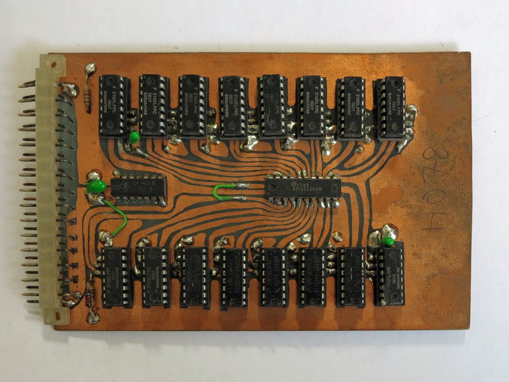
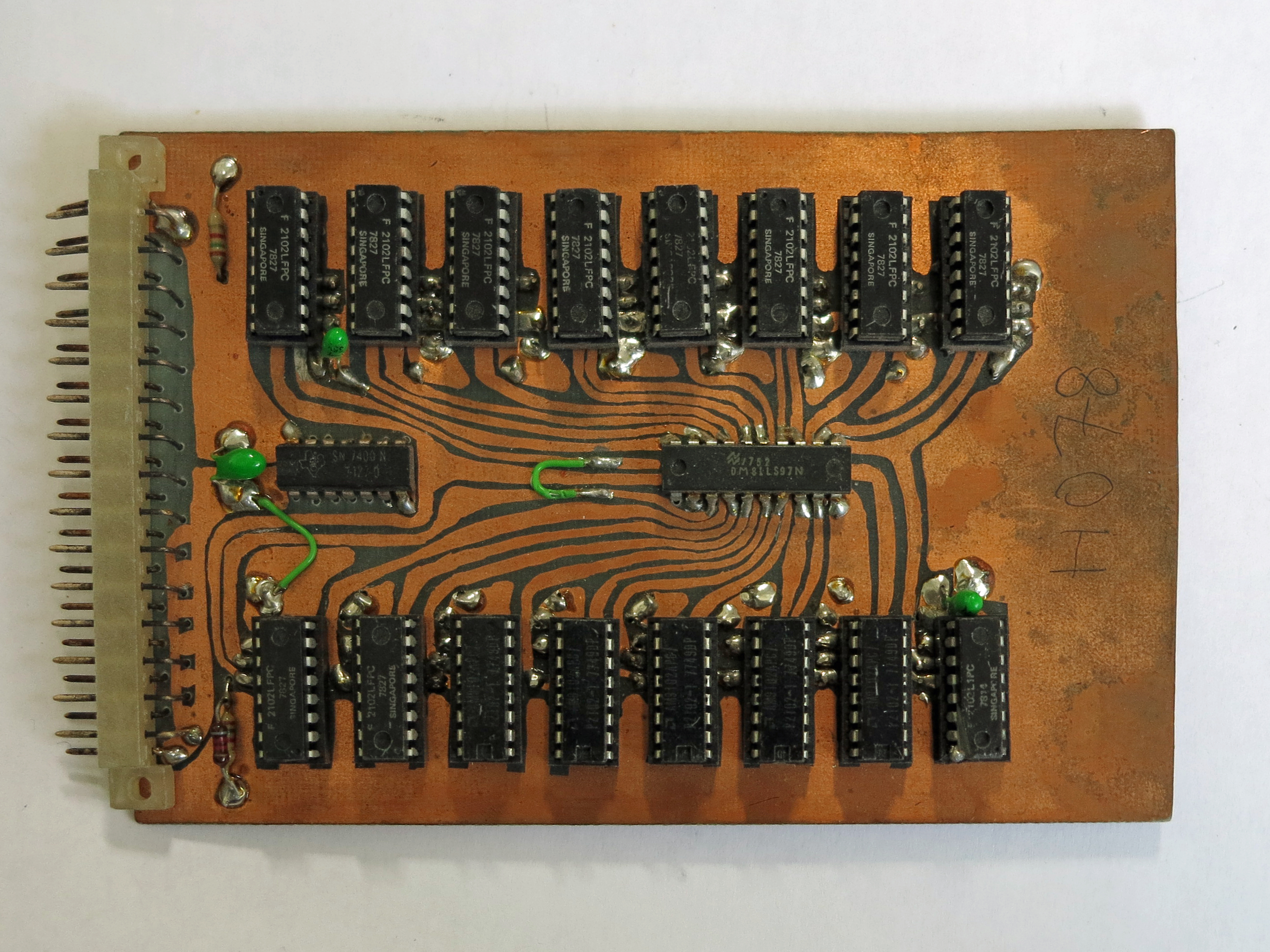
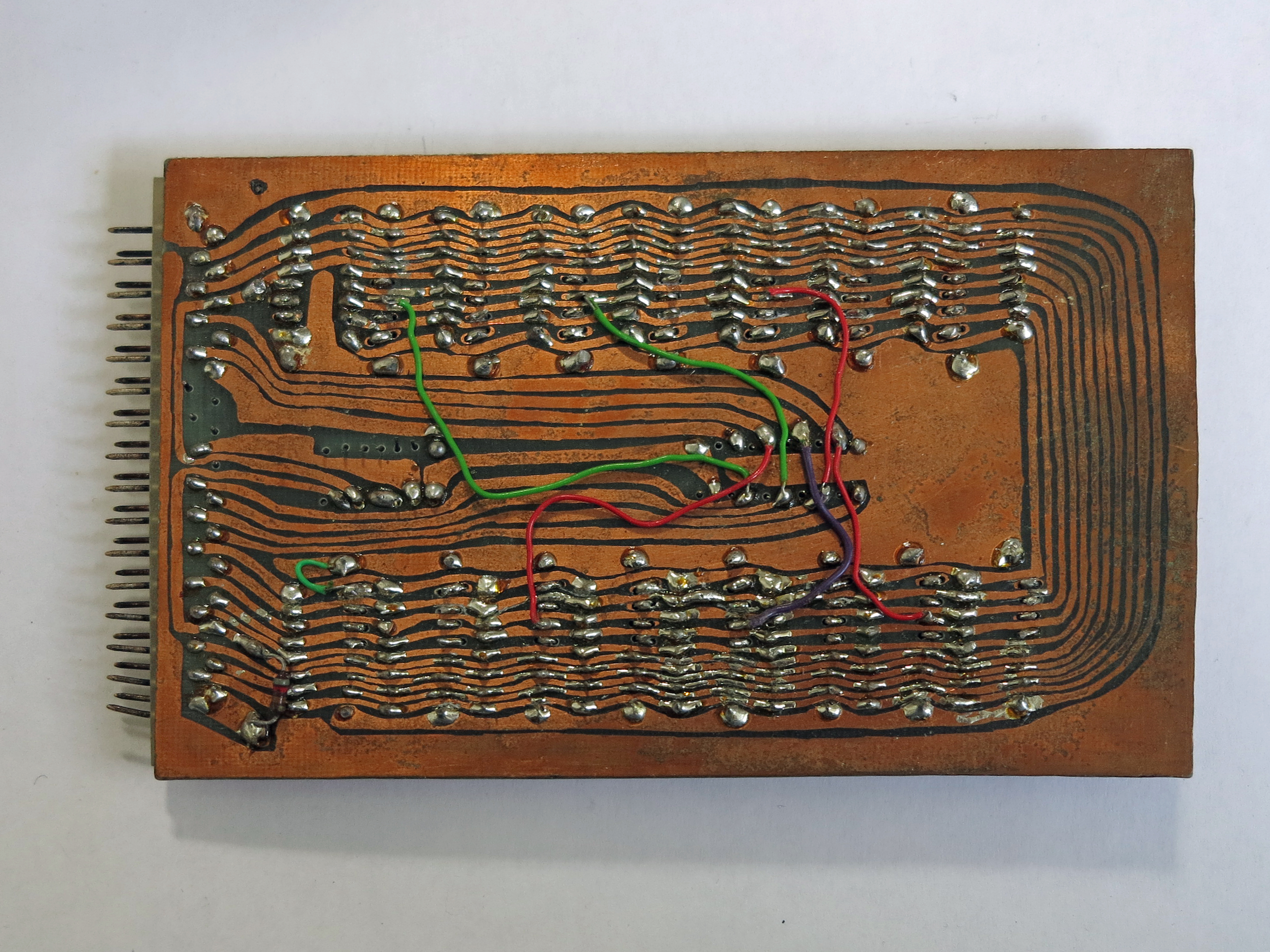
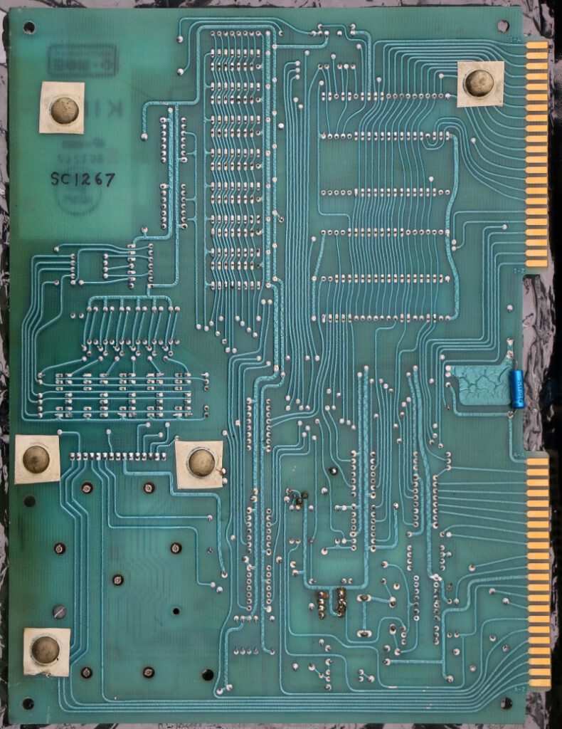
PCBs handmade, double sided!

Memory 2K RAM Card, BEM Bus Brutech Variant made by Hans Otten
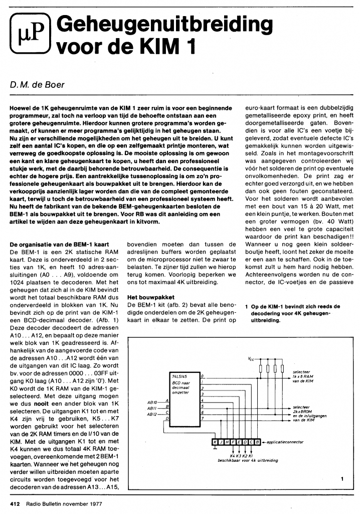
Memory boards were made myself by drawing with Edding ink on the blank PCB, etching and drilling. Filled with 2102 RAM IC’s for 1K per board, it filled lower RAM of the KIM-1 $0400 – $13FF. The bus is a 31 pin DIN connector, based upon the BEM (Brutech) bus.
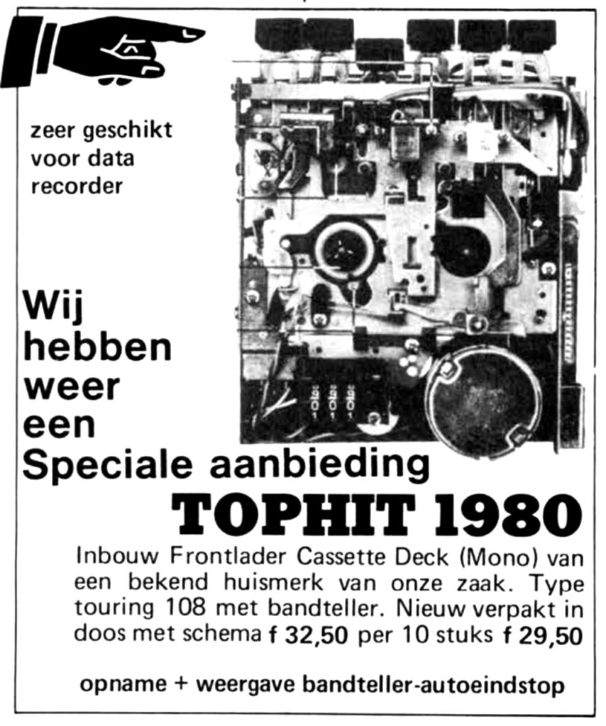
I bought two of this deck from Radio Service Twenthe, Den Haag, fascinating electroncis dump store!
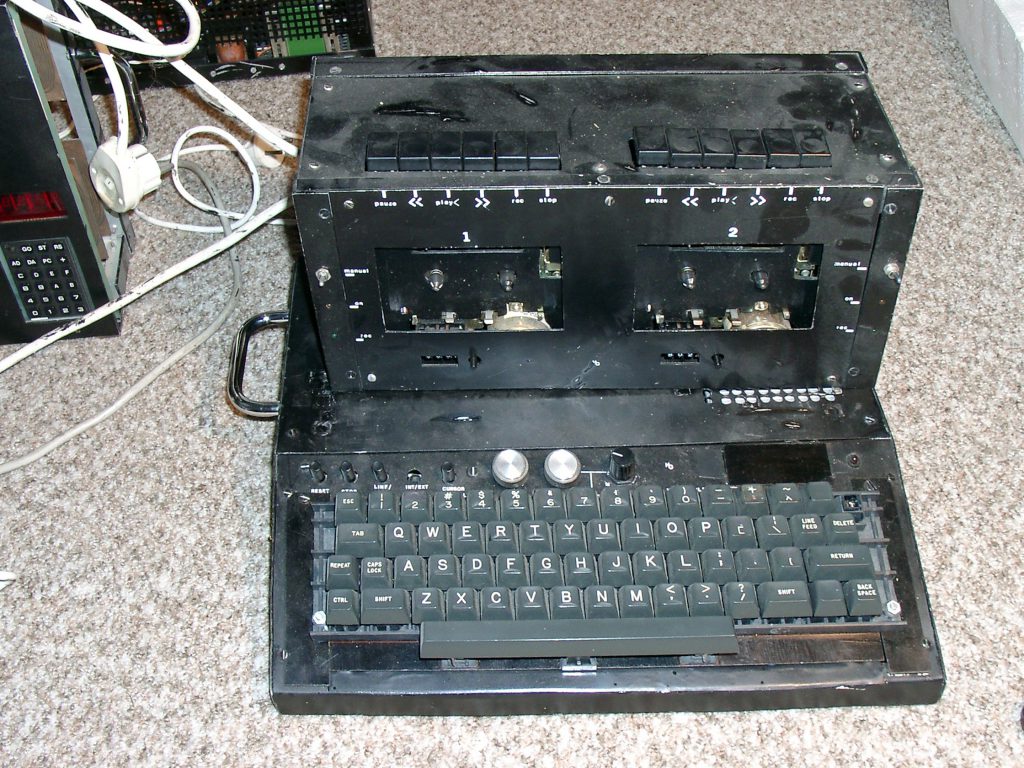
The next thing I built was a video display unit. All TTL 74XX logic IC’s, a 2513 character generator, a AY-5-1013 character generator, an ASCII keyboard, display on TV 32×32 characters uppercase. RS232 input/output to the KIM-1.
On top of the VDU a dual cassette deck is shown. From the famous Dutch dump shop Radio Service Twente two audio cassette decks were bought, some audio amplifiers and power supply added, and a remote control circuit via a 6532 GPIO line (standard as in Micro Ade). Served me well for many years, in 2014 the decks strings were dried out and crumbled after many years of not being used.
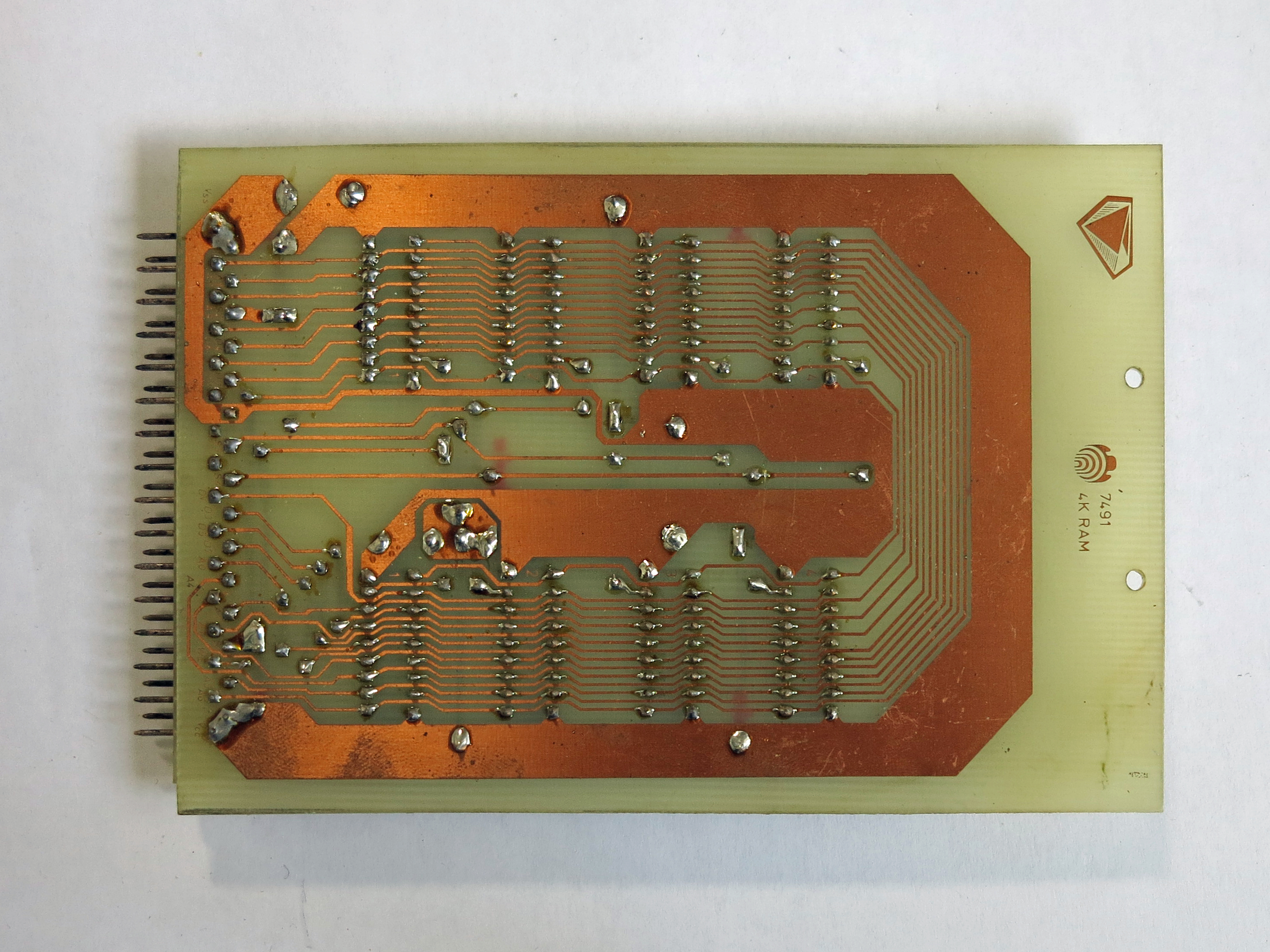
Next was a real expansion cabinet with a long backplane for 32K memory with 8x 4K RAM card, 2114 based, Designed by me, published in Radio Bulletin and sold by Visser Assembling Electronics. BEM bus compatible.
4K SRAM card
 4K SRAM card, Radio Bulletin September 1979 part 1 part 2
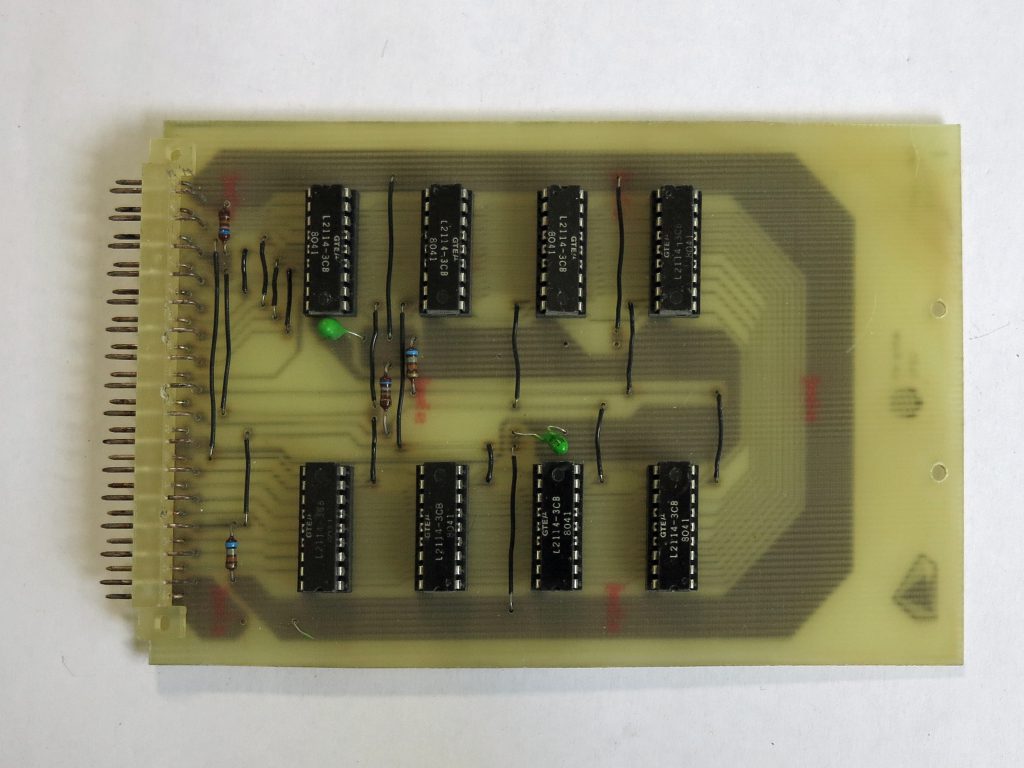
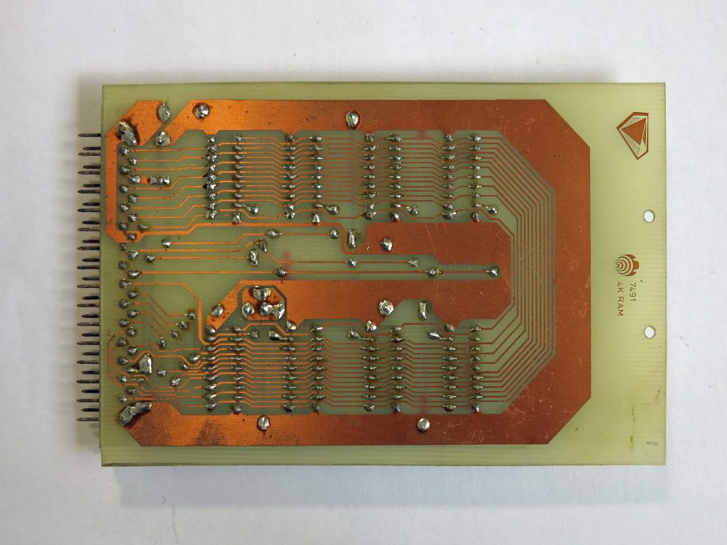
Production 4K RAM card
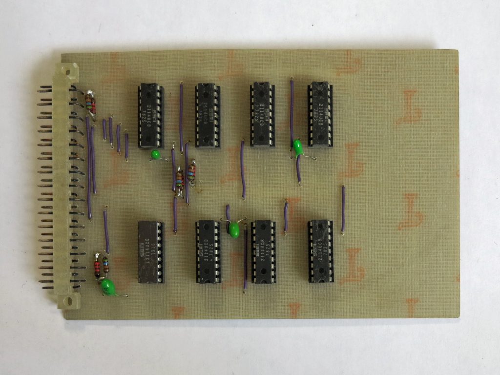
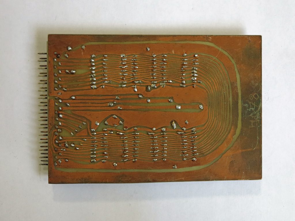
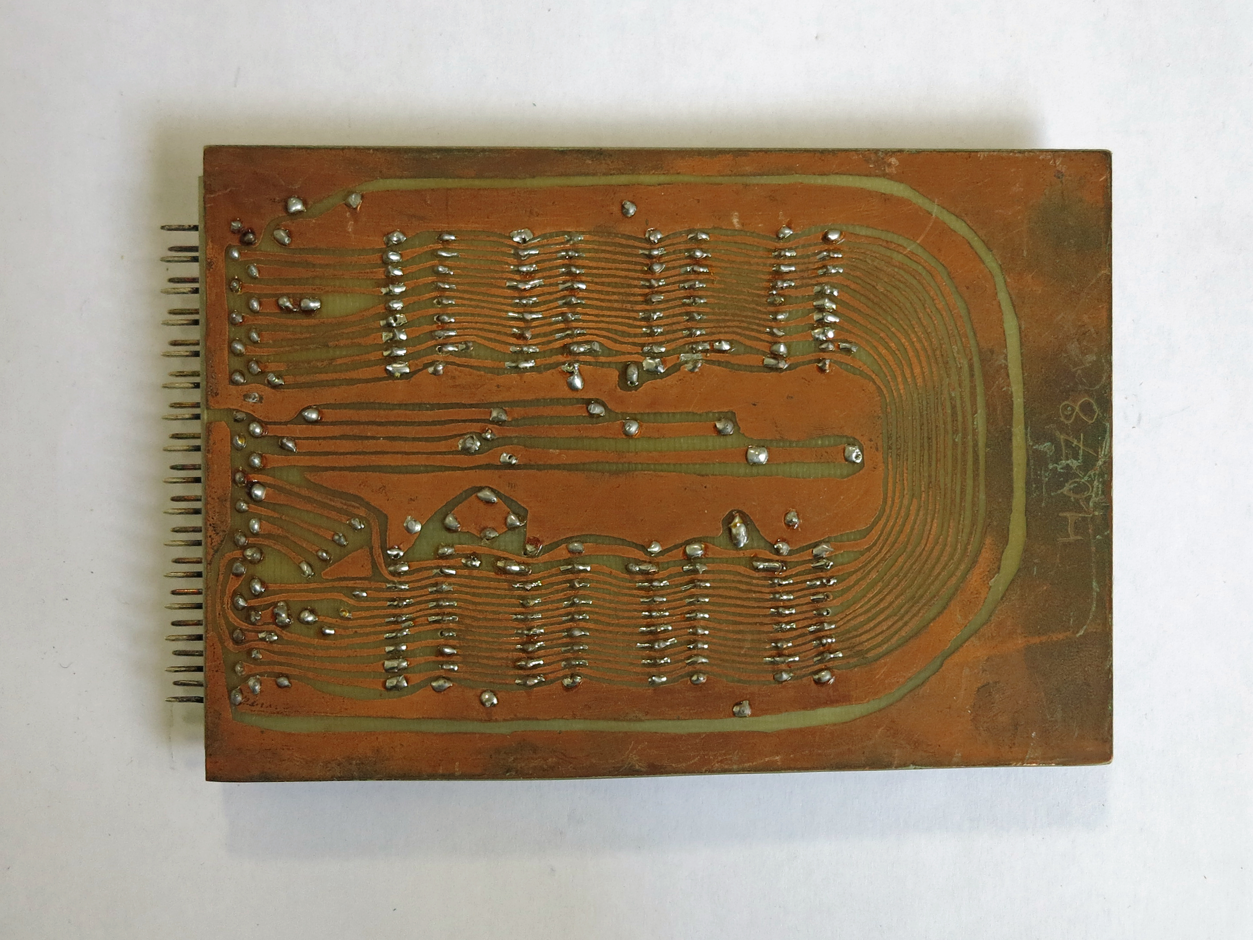
Prototype 4K RAM card, also hand drawn on the PCB!
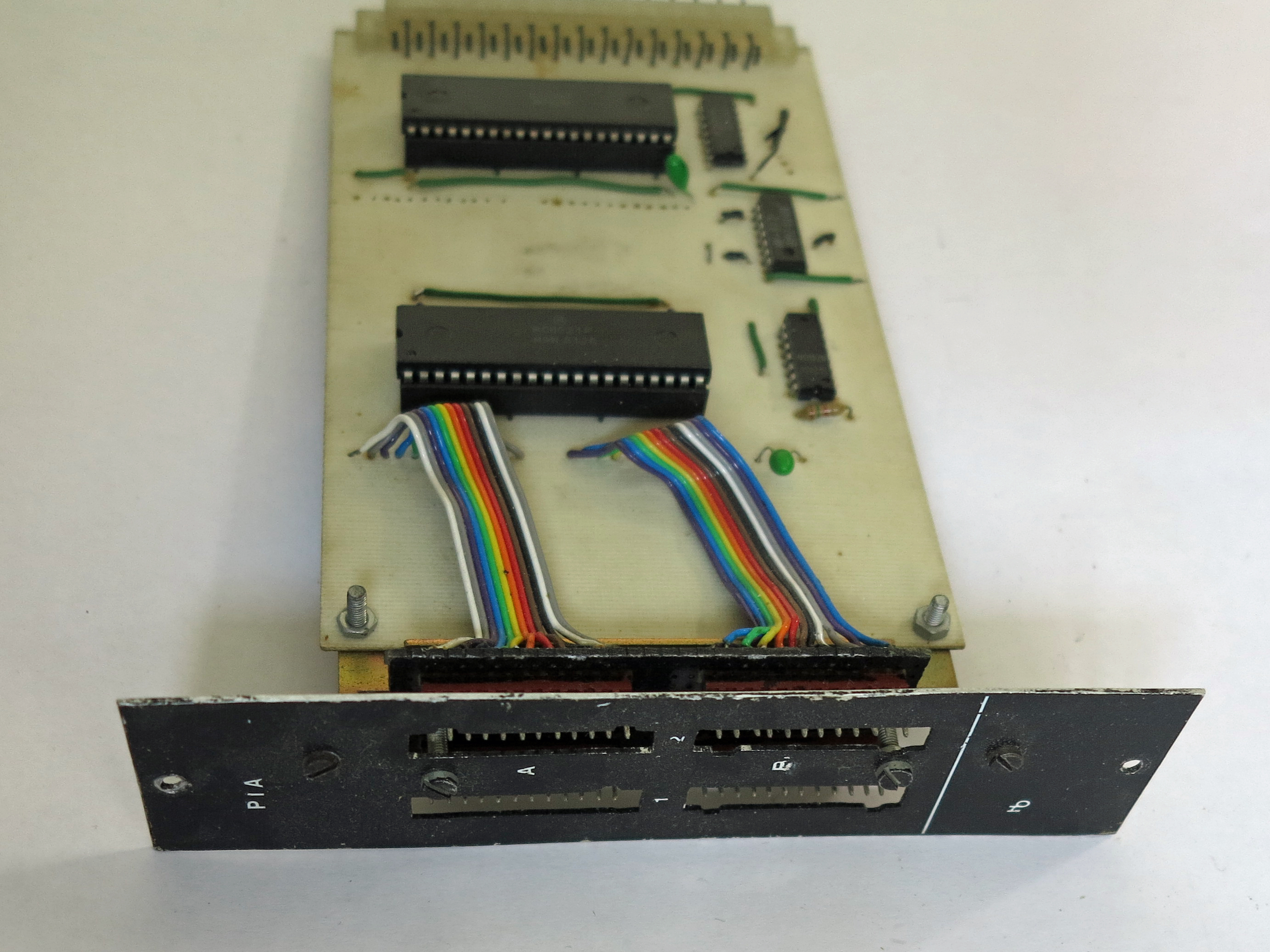
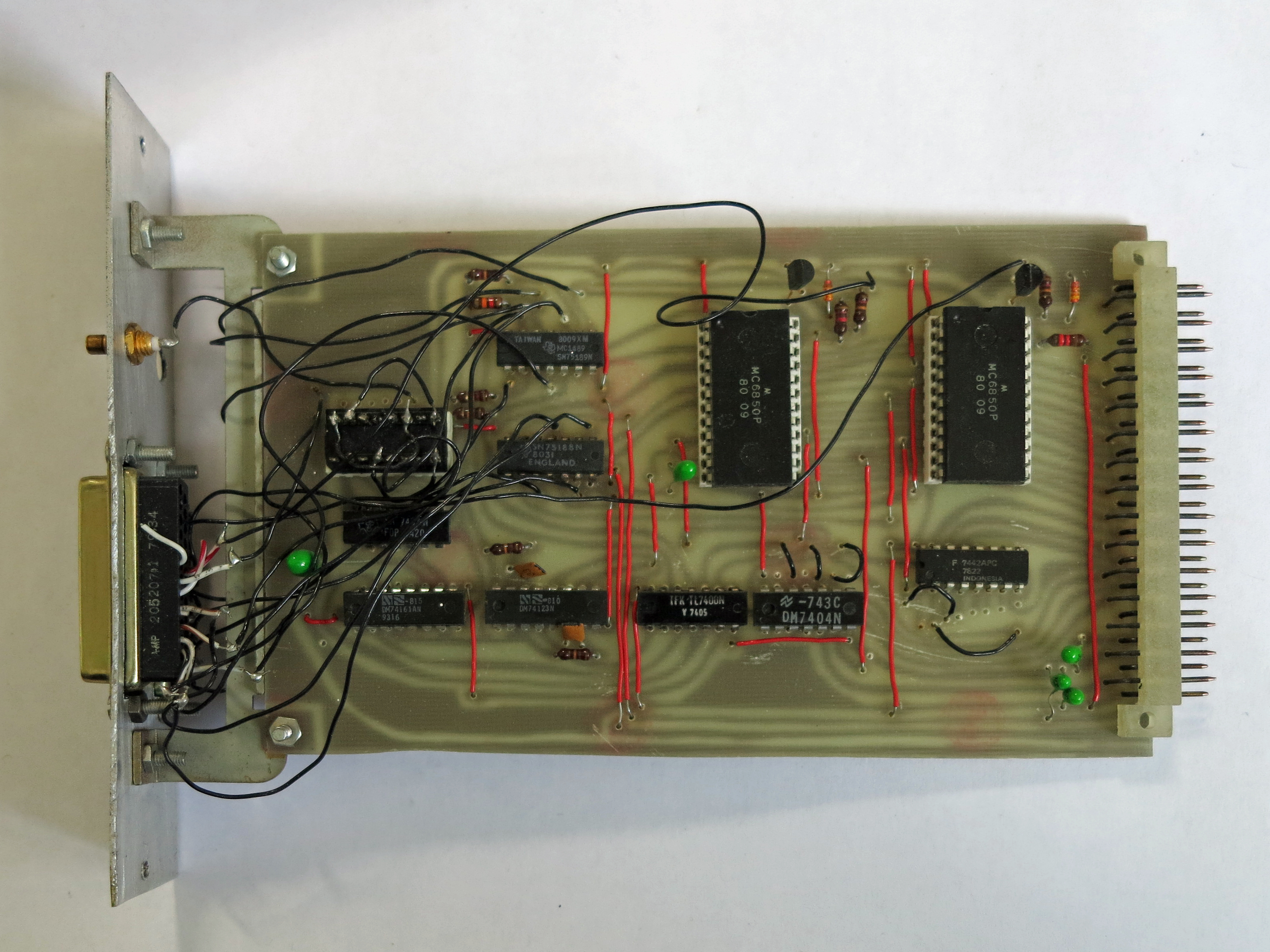
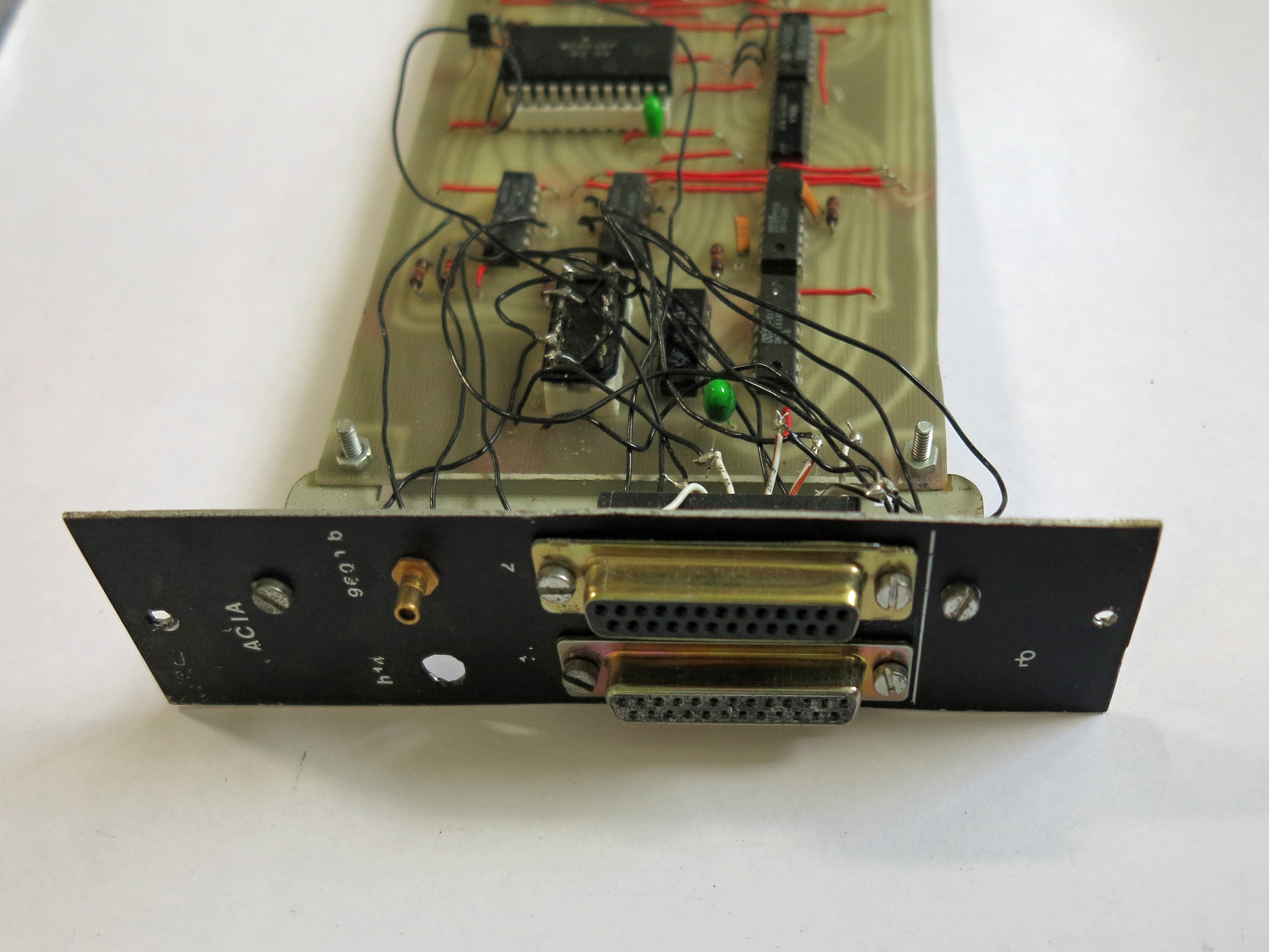
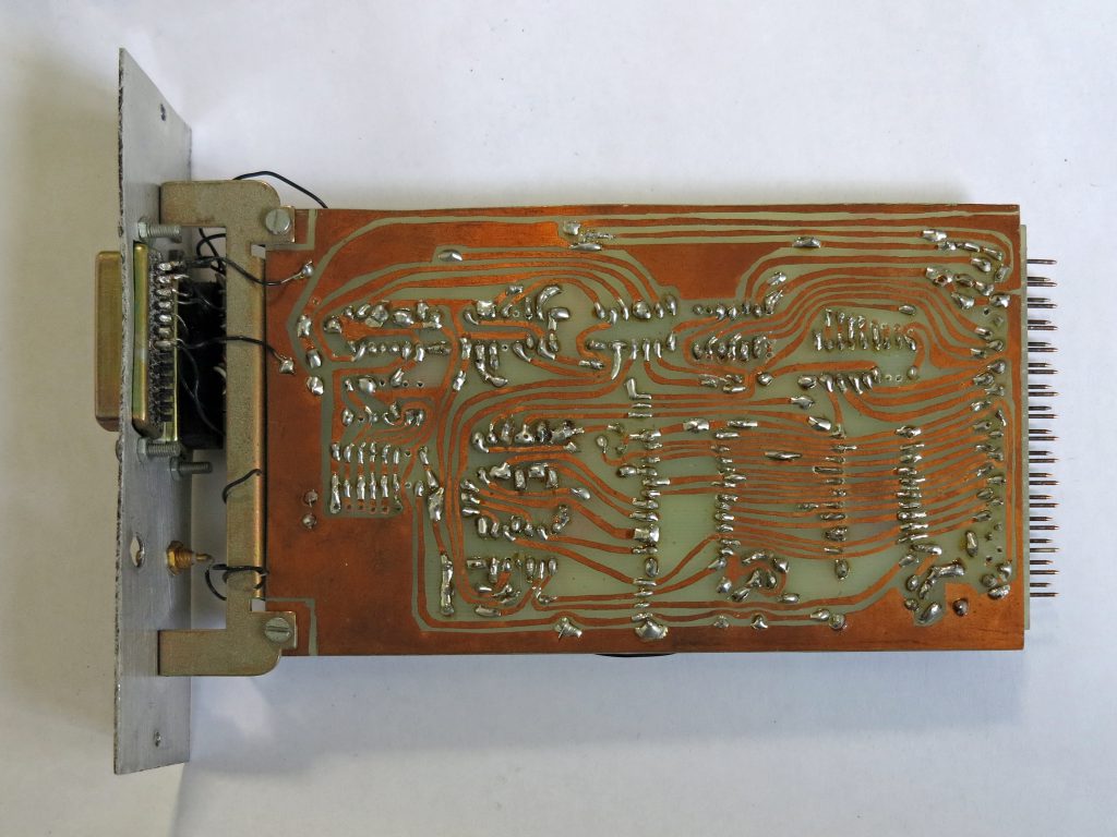
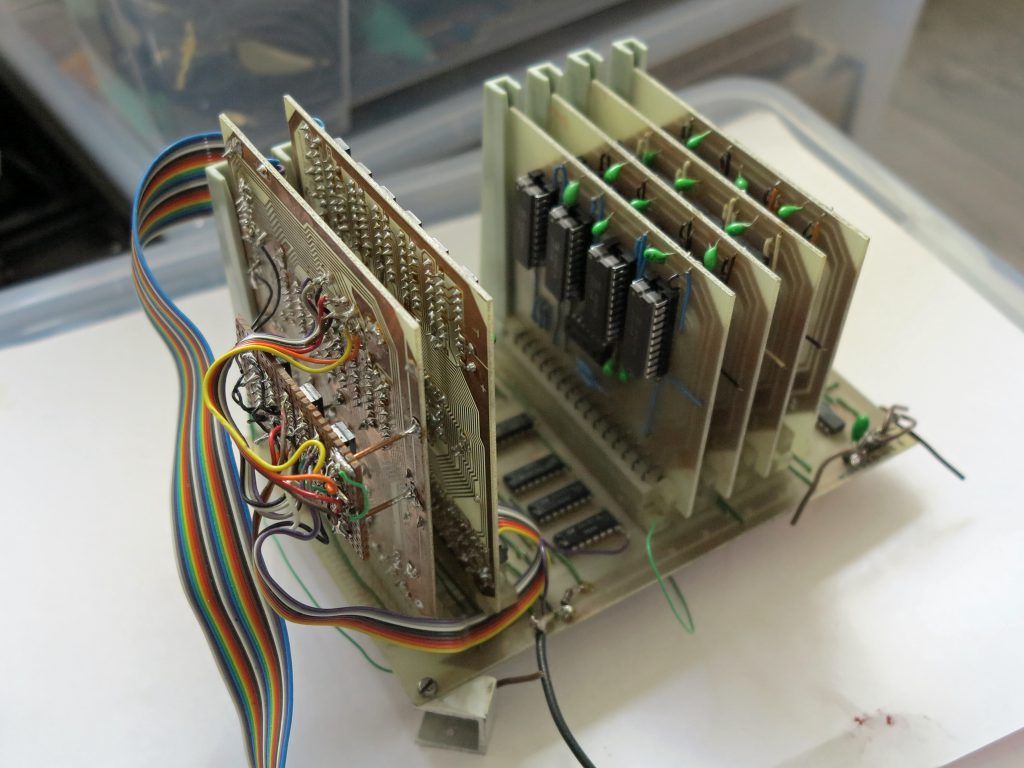
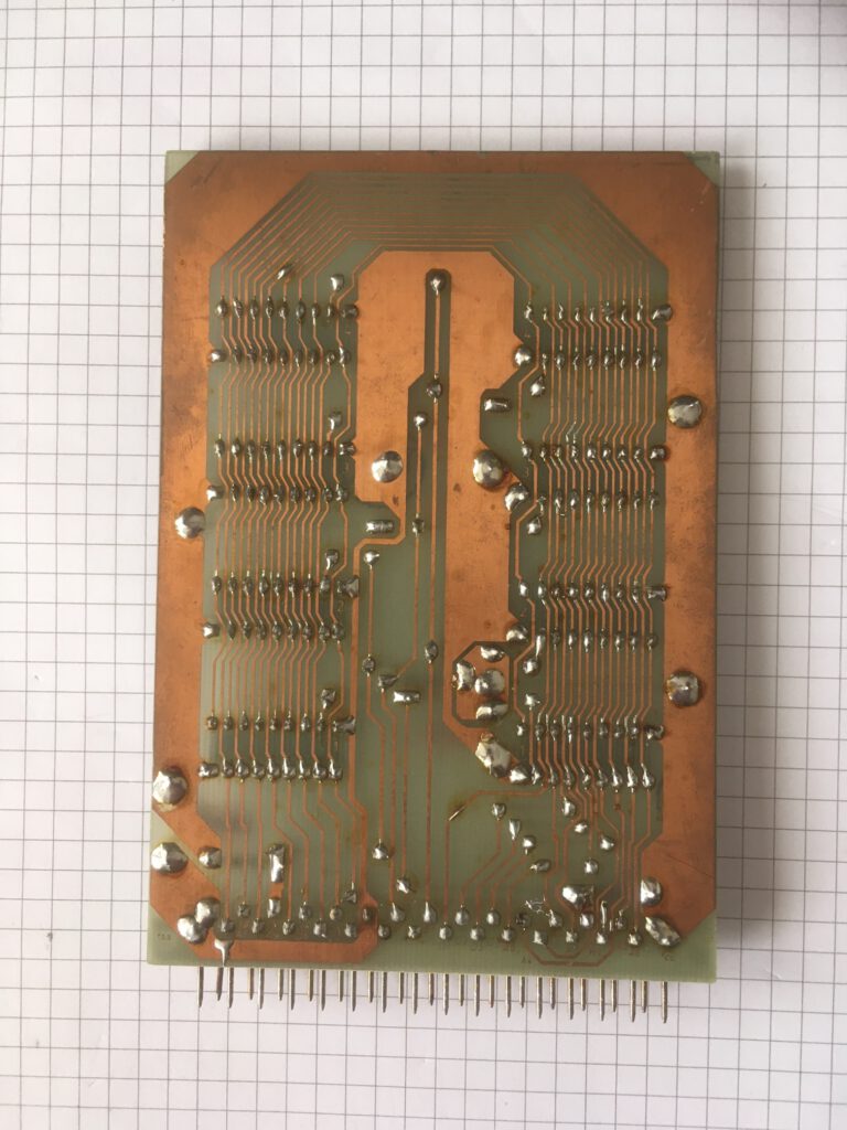
In the expansion cabinet three slots were added for I/O. Two cards were designed by me and published in Radio Bulletin: an ACIA card for two 6850 Motorola ICs, and a PIA card for two PIAs, 6522 or 6520 or 6820 or 6821. I never used more than one ACIA and one PIA card. Shown are the prototype cards, in the article production quality PCBs were used.
PIA and VIA card design by Hans Otten June 1984 Radio Bulletin
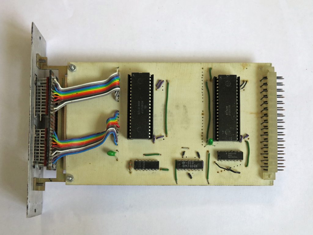
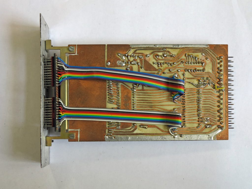

ACIA Motorola 6850 by Hans Otten, 1983 Radio Bulletin


On one of the ACIAs a VT100 Digital Equipment terminal was connected, taking over from the bit banged serial interface and the homebuilt video display. ON the other ACIA a Heathkit H14 matrix printer was added, a mediocre but adequate printer.


Together with Micro Ade as assembler and editor, the dual cassette deck, 40K RAM In total, this was a nice machine! Until 1987, when I bought the Spectravideo X’Press 738 MSX and CP/M system, used for all my publishing activities.
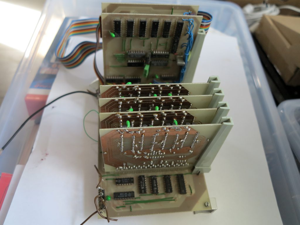
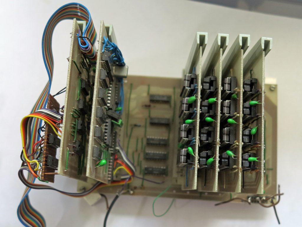
A third expansion cabinet was built around 1983. It was driven by the PIA’s, the Radio Bulletin Grafisch Display was inside the cabinet, along with two MDCR Philips Digital cassette recorders, alo published in Radio Bulletin. The speed difference between Hypertape audio cassettes and 2400 baud MDCR speed was not that impressive.
Dirk Dral
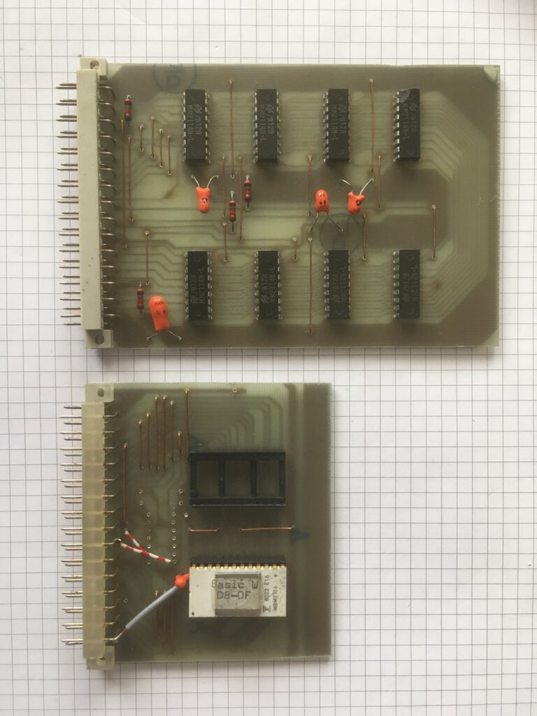
EPROM card (Dirk Dral)