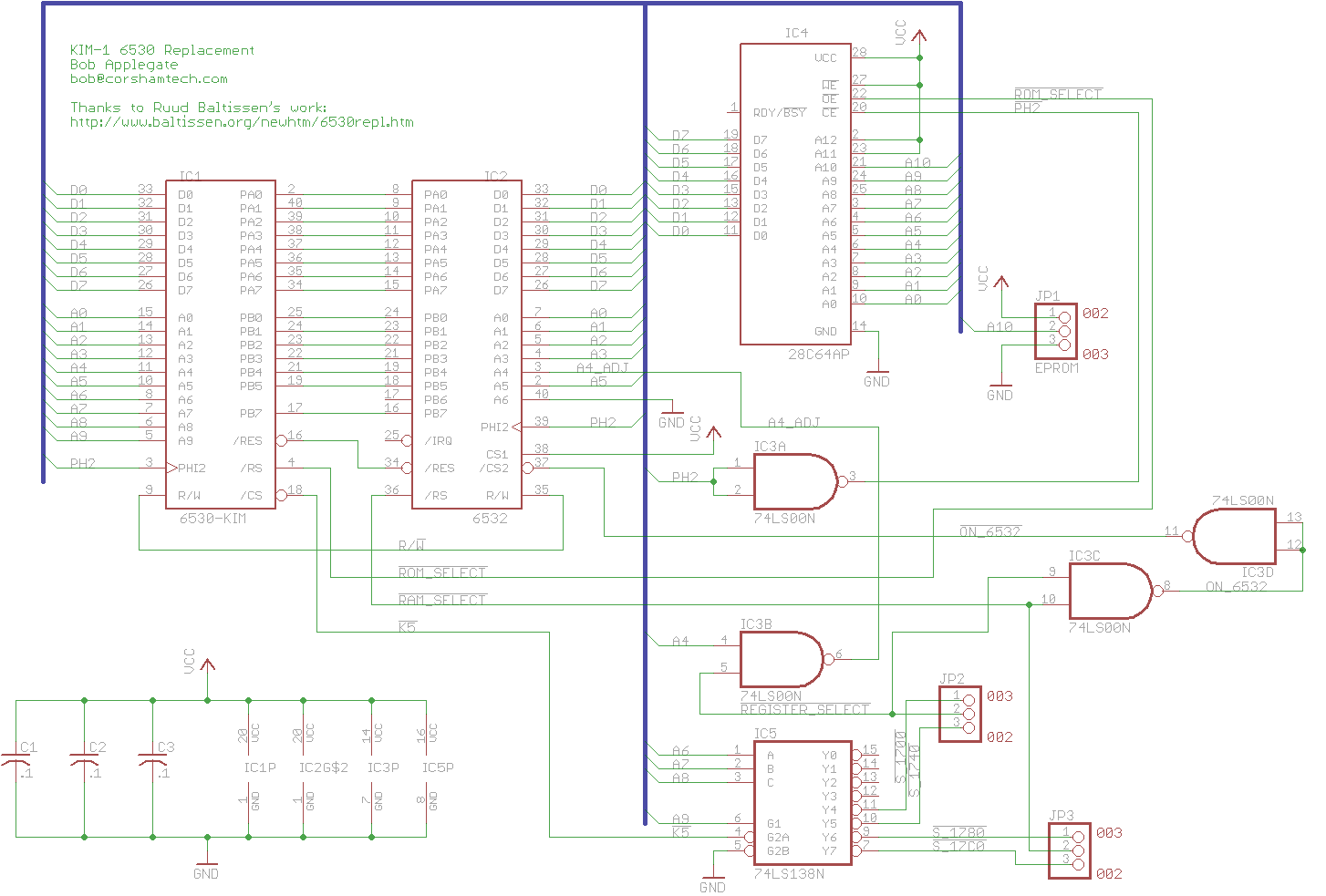
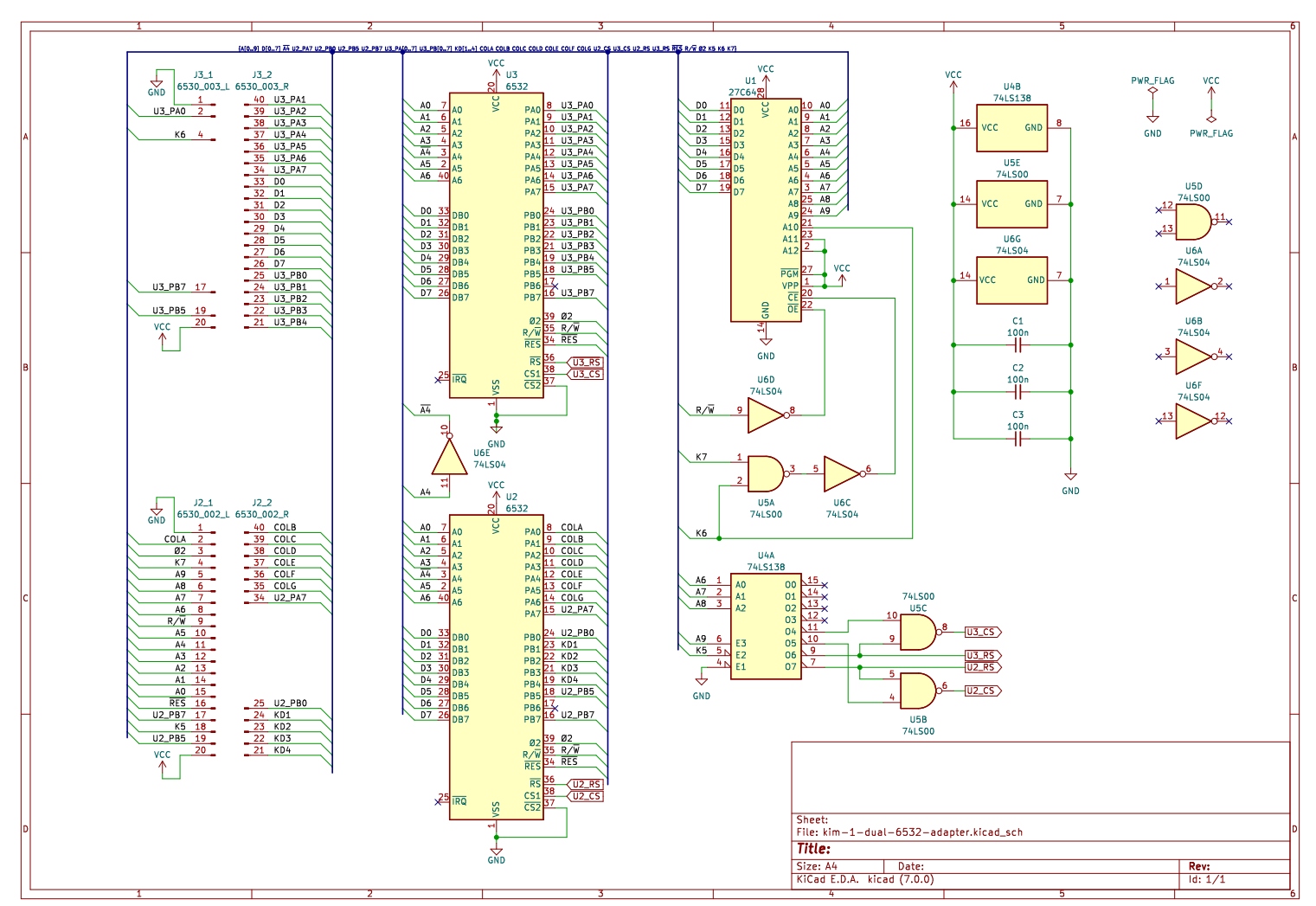
Like many people, I (Bob, Corsham Tech) have a KIM-1 in my collection with a dead 6530 chip. Fortunately mine wasn’t too bad, but one of the I/O pins didn’t work so the display always had one segment lit and the TTY port would not work. After many hours of searching for a way to replace this one defective chip with an equivalent circuit, it became apparent a lot of people were trying to do the same thing, some claiming to have a solution, some not, but no schematics ever appeared. Without schematics, there is no solution.
Rather than letting others go through all the effort to reverse engineer the 6530, I decided to make my own, and to publish the schematic. This work was heavily taken from Ruud’s excellent tutorial on his efforts to replace a 6530 in a Commodore disk drive. Please go to his page for an explanation:
http://www.baltissen.org/newhtm/6530repl.htm or see the 6530 pages here.
Since the 6530-002 and 6530-003 in the KIM have different mapping of ports, his exact schematic is not right for the KIM, so I borrowed some of his KIM-1 clone ideas and designed my board from it.
Notes
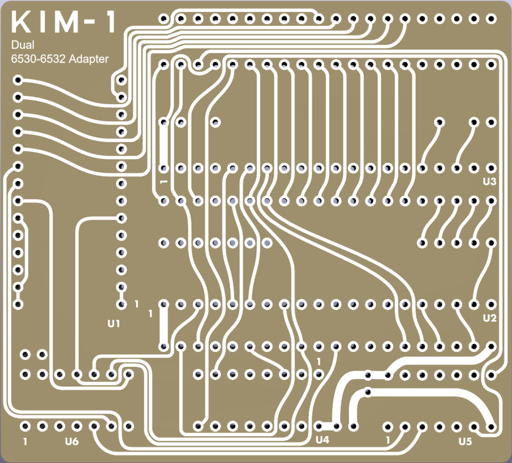
- No, the schematic is not pretty. I can spend some time and shuffle parts around to make the parts placement neater, but if you’re contemplating building this, I’m sure you’ll have no problems following the schematic.
- Pin usage has not been optimized. This was breadboarded but the PC board design is not done so some of the pins on the 74LS00 might change.
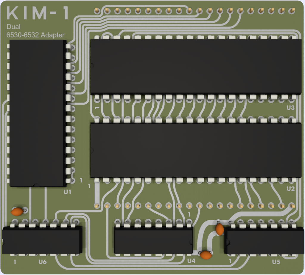
- There are three jumpers with U2 and 003. The intent was to be able to replace either of the two 6530s on the KIM and both U2 and U3 have been tested.
- A 28C64 EPROM was chosen because (A) they’re readily available, (B) common USB programmers can program them, and (C) the offset in an Intel HEX file for the KIM PROMs will be at the proper offset when you load the files into your programmer’s memory. Ie, the 002 device’s offset at 1C00 will be at offset 1C00 in the EEPROM.
Manual
PDF version of the manual.
EEPROM Contents
The basic KIM has an 8K memory map so using an 8K EPROM/EEPROM makes things easier because the address in the HEX file is exactly the right offset into the EPROM. If you don’t understand this, don’t worry, you don’t need to.
I deleted the two individual hex files and replaced it with a single file that covers both halves of the KIM PROM:
KIM-ROM.HEX
The image is a raw dump from a working KIM, not re-assembled from source. Note that I had to add an extension of txt so that WordPress would allow me to upload them, but take off that extension when you save them to your computer.
Design Files
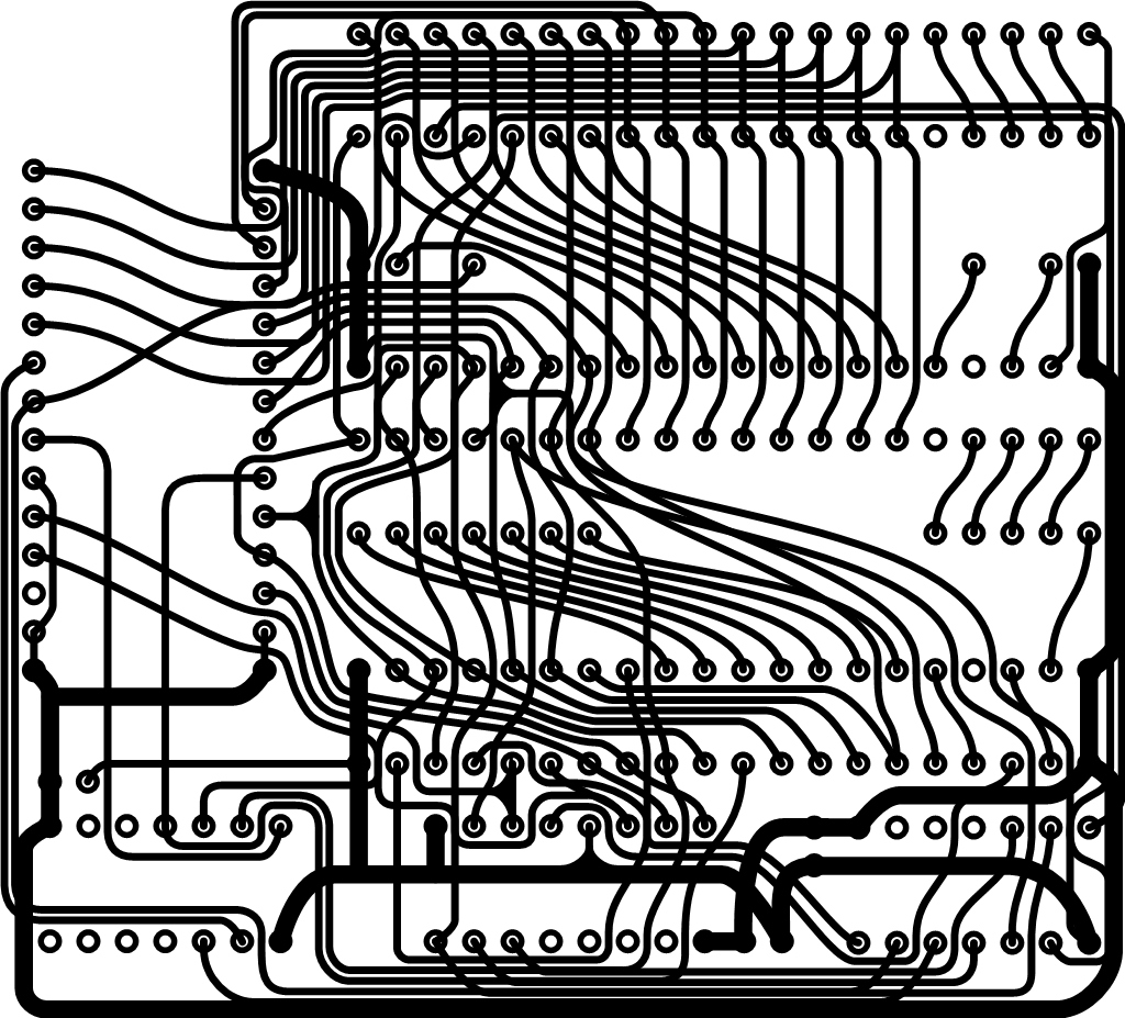
Bare boards are available, but these are the files you can use to generate your own. First, this is the GERBER file from the revision 1 boards I sent to have boards produced. If you want to make your own boards without any modifications then just upload this file to your favorite PC board manufacturer and they can give you a quote:
KIM_6530_rev_1
If you use the EAGLE CAD package, here are the files needed for the project. This has the epf, brd and sch files:
EAGLE_6530_rev_1
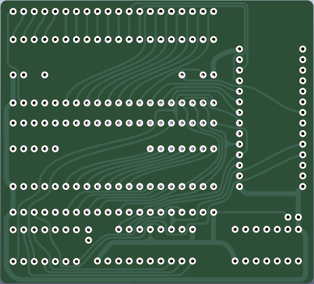
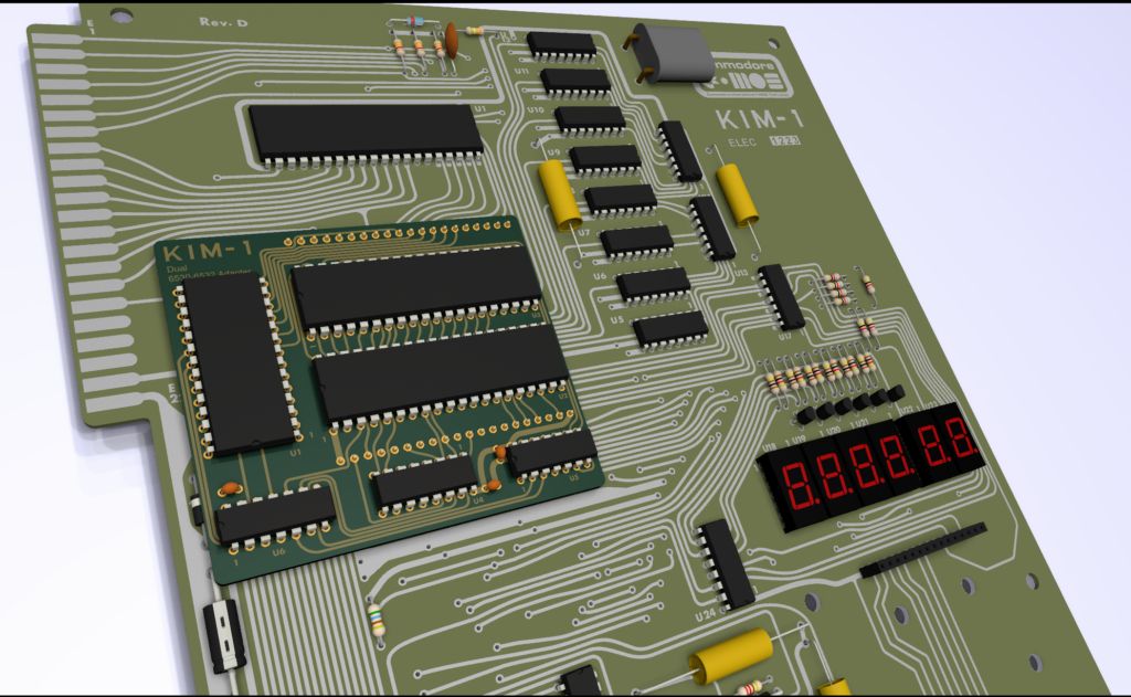
BTW, this is what the top layer of the board looks like, minus any traces:
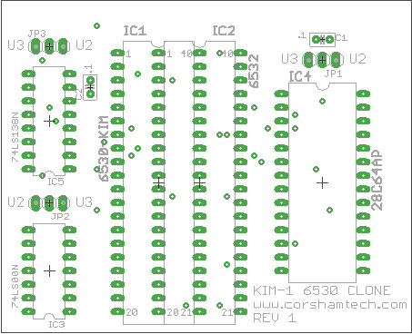
Just like Ruud’s original design, this has the 6530 header and 6532 socket overlapping each other. For the header that is soldered to the underside of the PC board and plugs into the KIM, I suggest a header with narrow pins. I used CNC Tech part number 220-1-40-006, available from Digikey as part number 1175-1527-5-ND. Be aware that the cross-pieces of the IC socket and the header will block the pins for the other, so you’ll need to cut them from either the socket or the header (whichever you solder last).
VERY IMPORTANT: Notice that IC3 and IC5 are polarized exactly opposite from the others! When you insert sockets and chips, double-check you’ve got them oriented in the right direction!
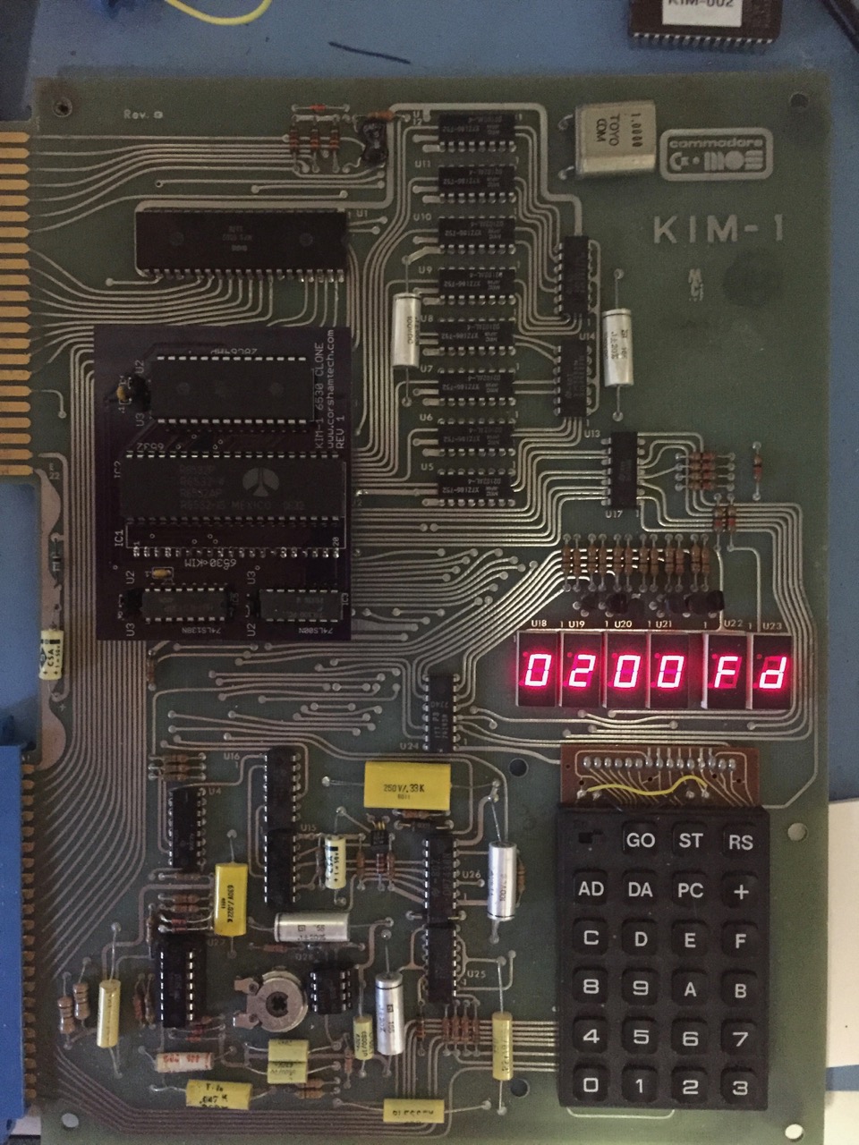
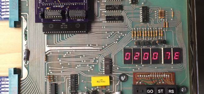
Prototype in action!
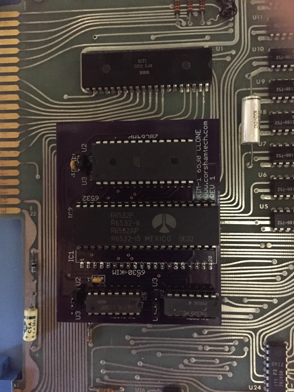
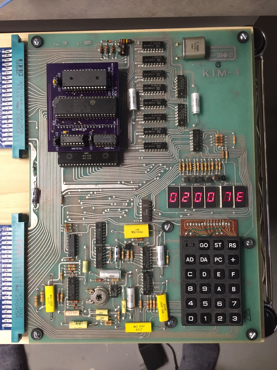
Replacement board in U3 location, works!


