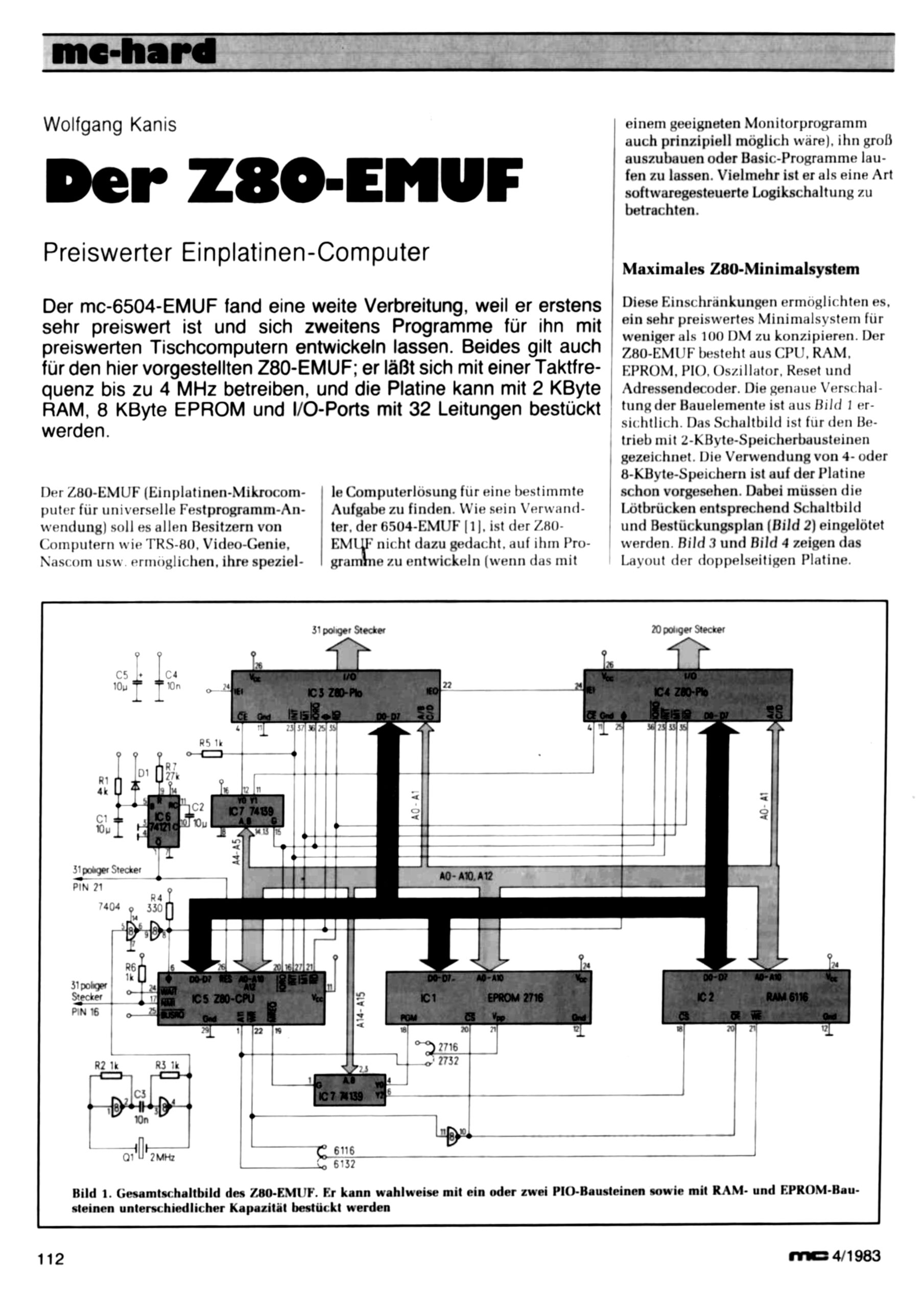
The original Dutch and later international electronics magazine in thee arly microprocessor years did not only pay attention to the 6502, also SC/MP and Z80 were used in designs.
While building the Retro Chip Tester, designed by Stephan Slabihoud, and documented on his 8bit-museum website, I noticed Stephan also designed CPU NOP testers and made designs as gerbers and BOM available. With the PCB of the Retro Chip tester I laso bought the PCB’s for 6502 and Z80 NOP tester from him. NOP testers are very simple test devices and in no way a real CPU stress test. Enough to discover if the IC is not a fake or severely damaged and not fit to be tested in a real system.
The idea of NOP testers is not new, for example Lee Davison documented his NOP tester for the 6502 here.
Stephan made the NOP testers standalone devices. Besides the socket for the CPU to test a clock signal is generated with a 555, a push-button does the reset, the minimal of control lines is connected to ground or puleld high, power is supplied with a USB connector.
The clock oscillator has a very low frequency, so you can see the address lines change by observing LEDs connected. This means the NMOS 6502 and Z80 are operated way below their minimal frequency, e.g. 100KHz for a 6502. The CMOS versions are static and can be driven with this low frequency.
In my experience with these testers is that the NMOS versions of 6502 and Z80 do work with this tester though, but I have seen good 6502’s start off well but after a minute crashed with all LEDs flashing in the tester. So not a definite test for NMOS! An interesting modification would be to have a higher clock frequency (1MHZ at least) and inspect all the address lines with an oscillosope.
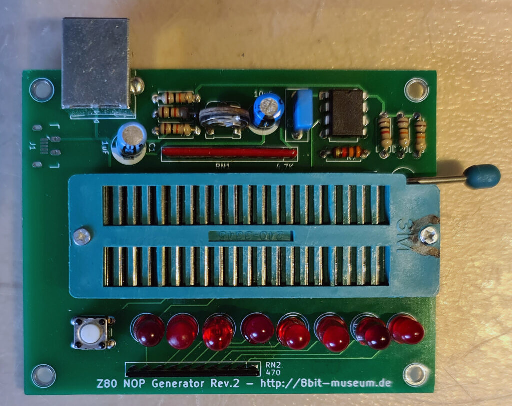
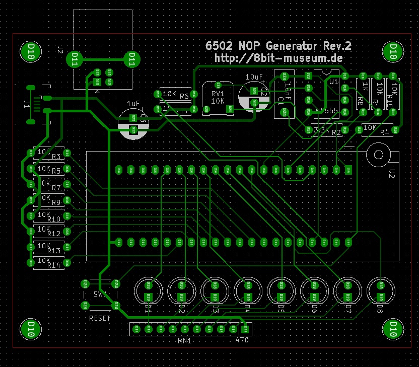
Used in a 6502 NOP generator , a 6502 CPU only executes NOP commands (No Operation). The low eight address lines can be observed with the aid of LEDs. If the CPU executes the NOPs, the addresses should be continuously incremented. This does not allow a complete test of the CPU, but at least a quick-n-dirty check.
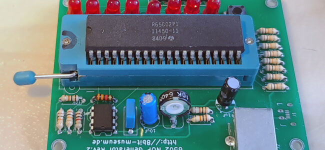
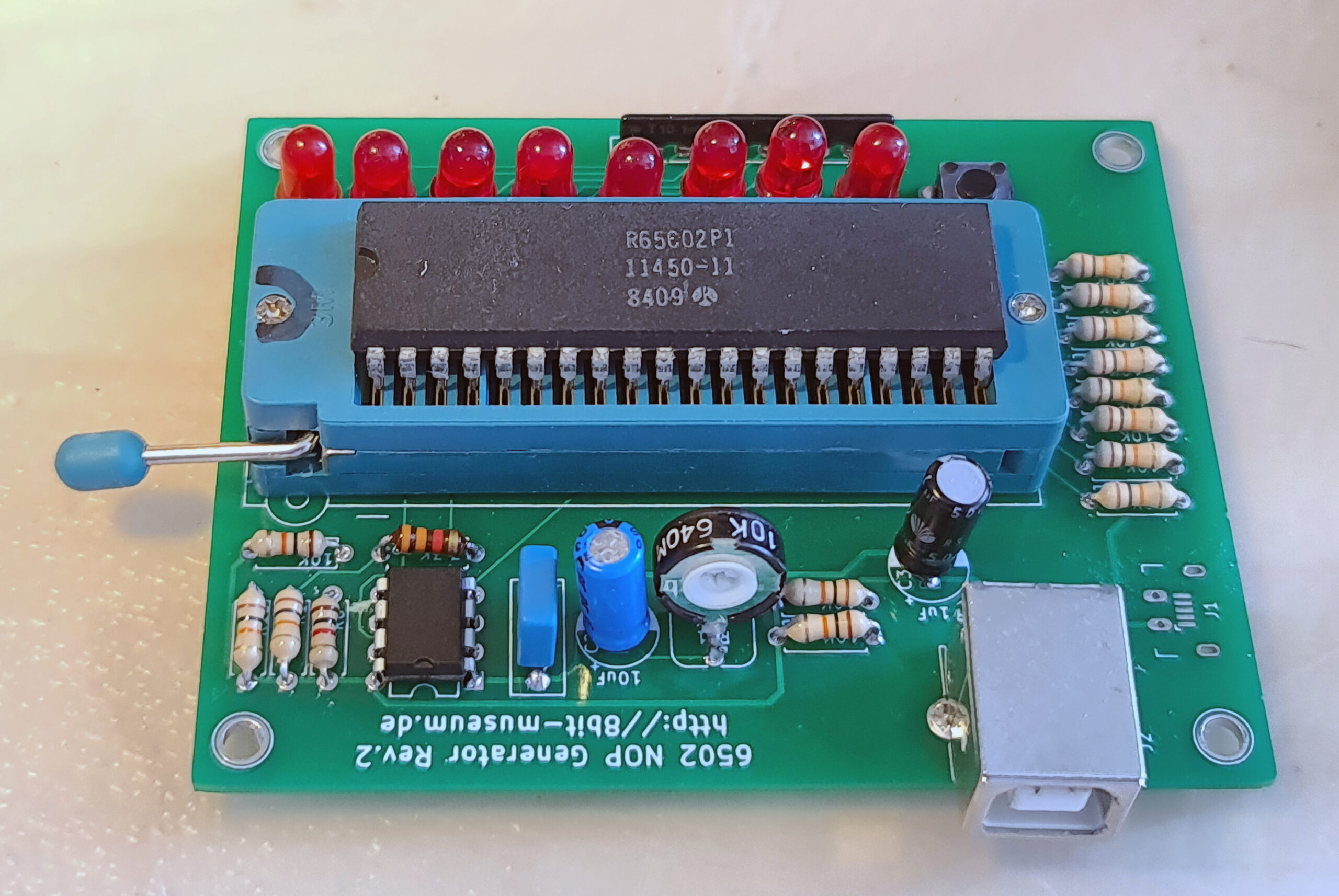
The 6502 NOP generator in action:
The 6502 NOP generator supplies the opcode 0xEA, which corresponds to a NOP for the 6502. After a reset, the 6502 NOP generator starts to count from address 0xEAEA (after a reset the CPU reads the real start address from addresses 0xFFFC-0xFFFD and since this always reads 0xEA, this is 0xEAEA). The LEDs should start counting at 11101010.
It is very nice to see how after the reset the addresses 0xFFFC and 0xFFFD are accessed first (before that a little initialization of the CPU), in order to then count from 0xEAEA (LEDs: FC, FD, E9, E7, EA, E9, FD, [FF] FC, [FF] FD, [EA] EA, EB, EC, ED, EE, EF, F0, F1 .., the upper 8 bits added in square brackets for understanding).
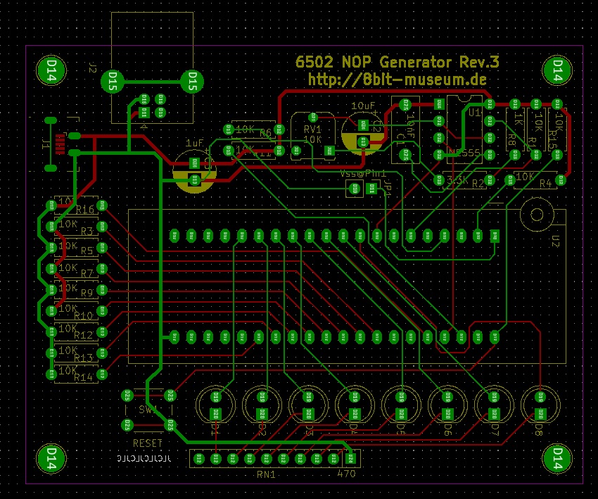
Changes for WDC65C02
While the 6502 NOP Generator has been designed for the 65C02 and 6502 pinout, it can be modified to work with the still available WDC65C02 variant. Differences between the variants are minor but essential:
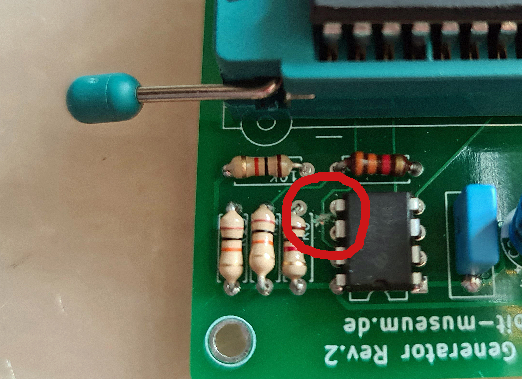
VPB Vector-Pull output Pin1 must be left open, on the 6502 and 65C02 this is the (second) Ground pin, On the PCB pin 1 is connected to ground, easy to cut track, see the photo below.
Pin 36 BE (Bus Enable) Connect a resistor 10K to VCC. Easy to add on the bottom of the PCB. pin 36 is NC (Not Connected) on 6502 and 65C02.
The latest gerbers on teh site of 8bit-museum have these modifications!
Cut the track on the PCB in the red ring, GND to Pin 1
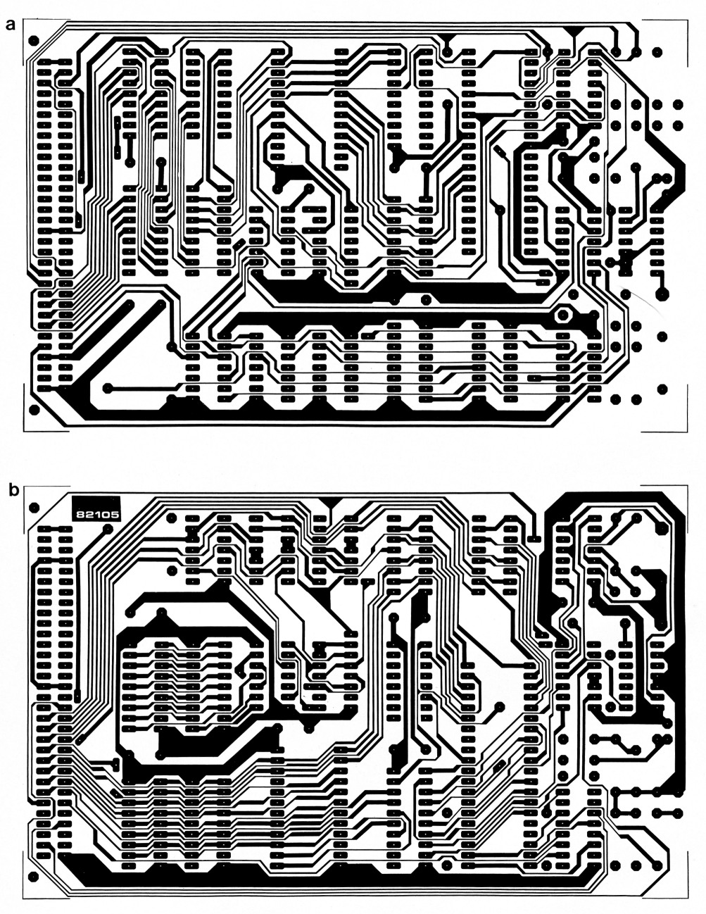
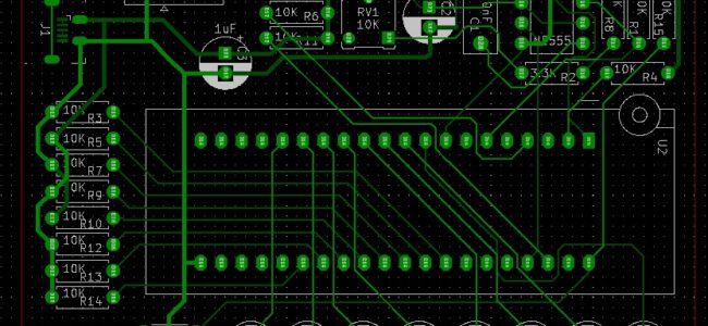
Gerber view in Kicad tool
V.3, has a jumper for Gnd on Pin 1 or not, and a 10K resistor on pin36 BE
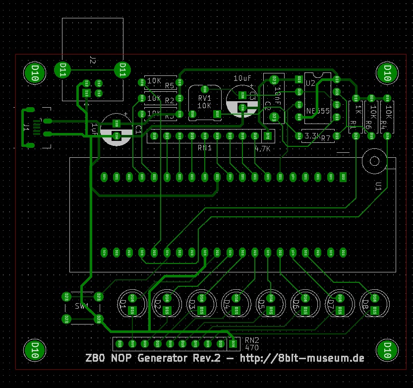
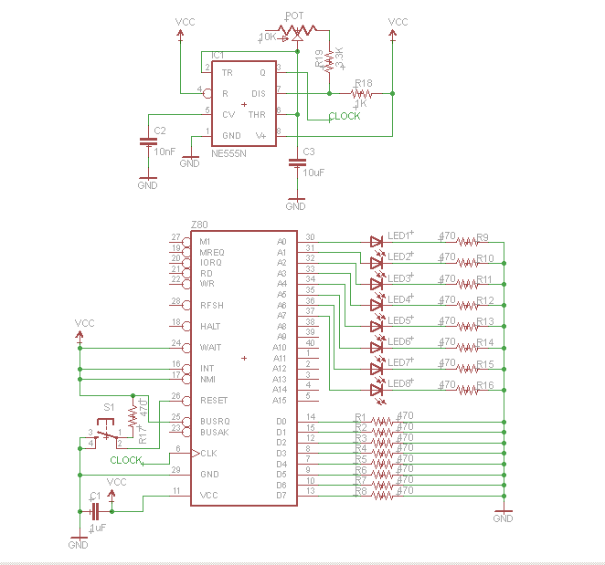
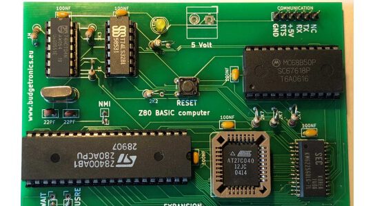
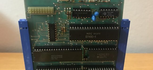
Z80 NOP tester
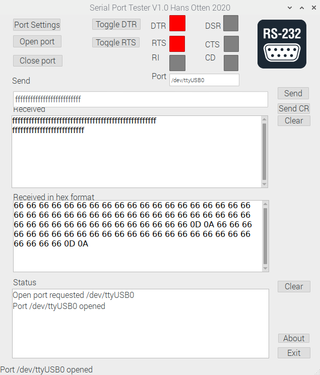
When used in a Z80 NOP generator , a Z80 CPU only executes NOP commands (No Operation). The low address lines can be observed with the aid of eight LEDs. If the CPU executes the NOPs, the addresses should be continuously incremented. This does not allow a complete test of the CPU, but at least a quick-n-dirty check.
The NOP generator presented here only works with Z80 CPUs. Since the CPU is clocked very slowly, far outside the specification, it is quite possible that an actually functional CPU does not work with the NOP generator. The way it works is very simple: The data lines are pulled to ground by pull-down resistors, so that the CPU reads a NOP (opcode 0x00) when the memory is read. After a reset, the CPU starts executing these commands from address 0.
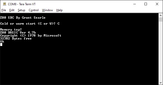
Parts are as expected from Grant’s design, except the EPROM, which is a 27C04012JC. in a PLCC case. A bit overkill (512Mb for a 8K ROM!) but cheap I suspect.
The ROM contents are the Nascom Basic adapted by Grant for a serial terminal. A typical Microsoft Basic of the early microcomputer days.
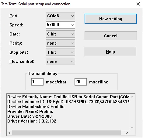
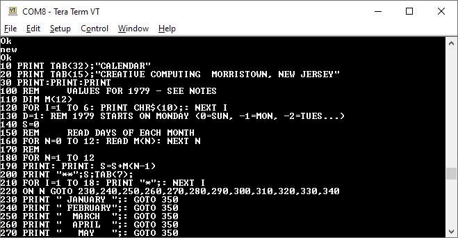
Connect a serial terminal, e.g. an USB TTL Serial cable to the PCB, start Tera term (Windows) or Minicom (linux), set the serial port to the COM/xTTYUSBxx port, speed 57600, no hardware handshake (or to hardware control connect if CTS to RTS connection available). If no hardware handshake, then you will have to adapt the delays after receiving character (1ms) and line (20ms) to prevent overruns on uploading Basic program text file. For me this worked out in Tera Term as shown in the next screenshot:
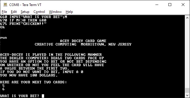
Without any storage facilities this computer is really only usable with a PC as terminal emulator to send files, as if the charaters in the file were typed in.
The same for saving, grab the ASCII output (the log facility in Tera Term for example).
Nice compact design, works perfect within its limitations.
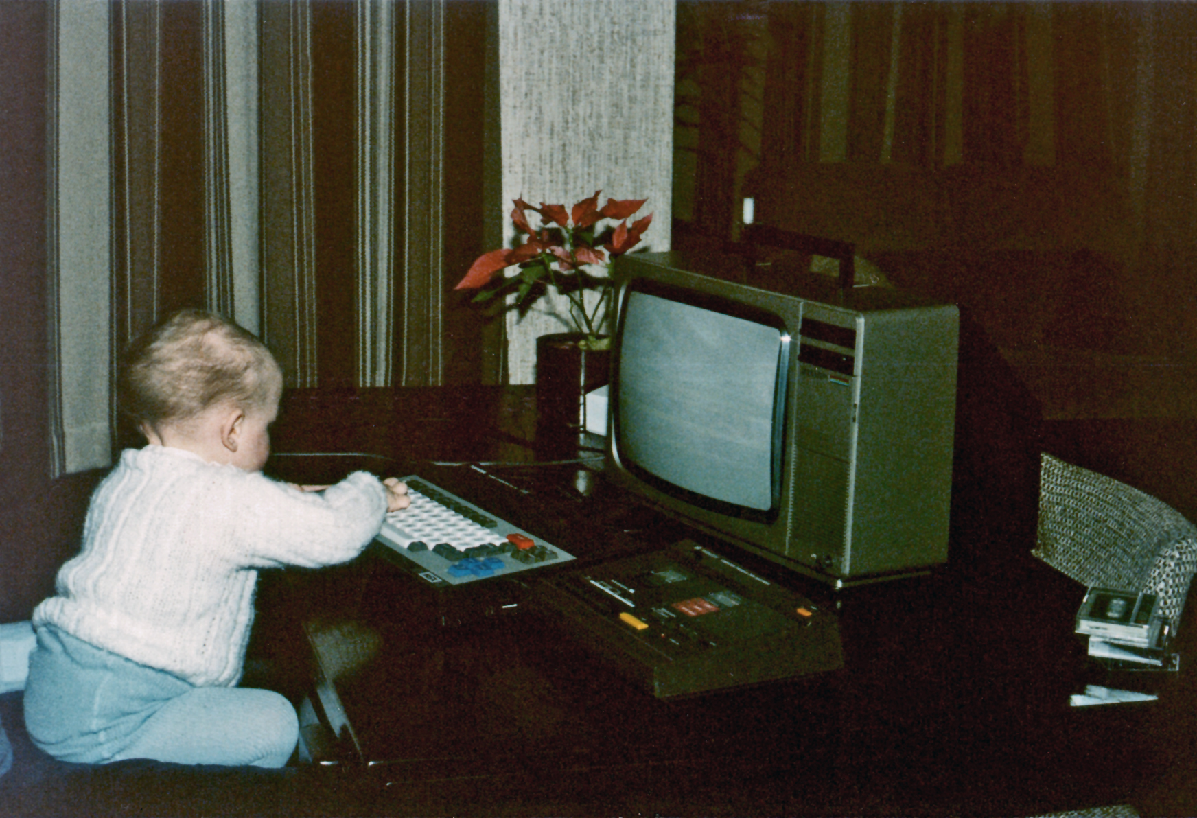
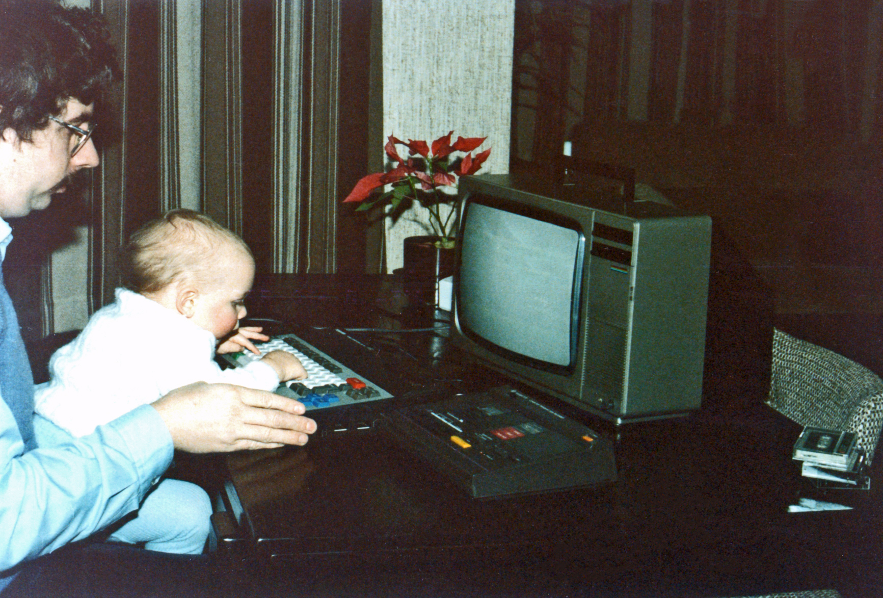
In 1984 I bought my first MSX, a Toshiba HX-10. A toy machine. Fun, but only suited for games. Z80, MSX-Basic, 64K, video (40×24 characters, graphics, color), audio cassette recorder for storage.
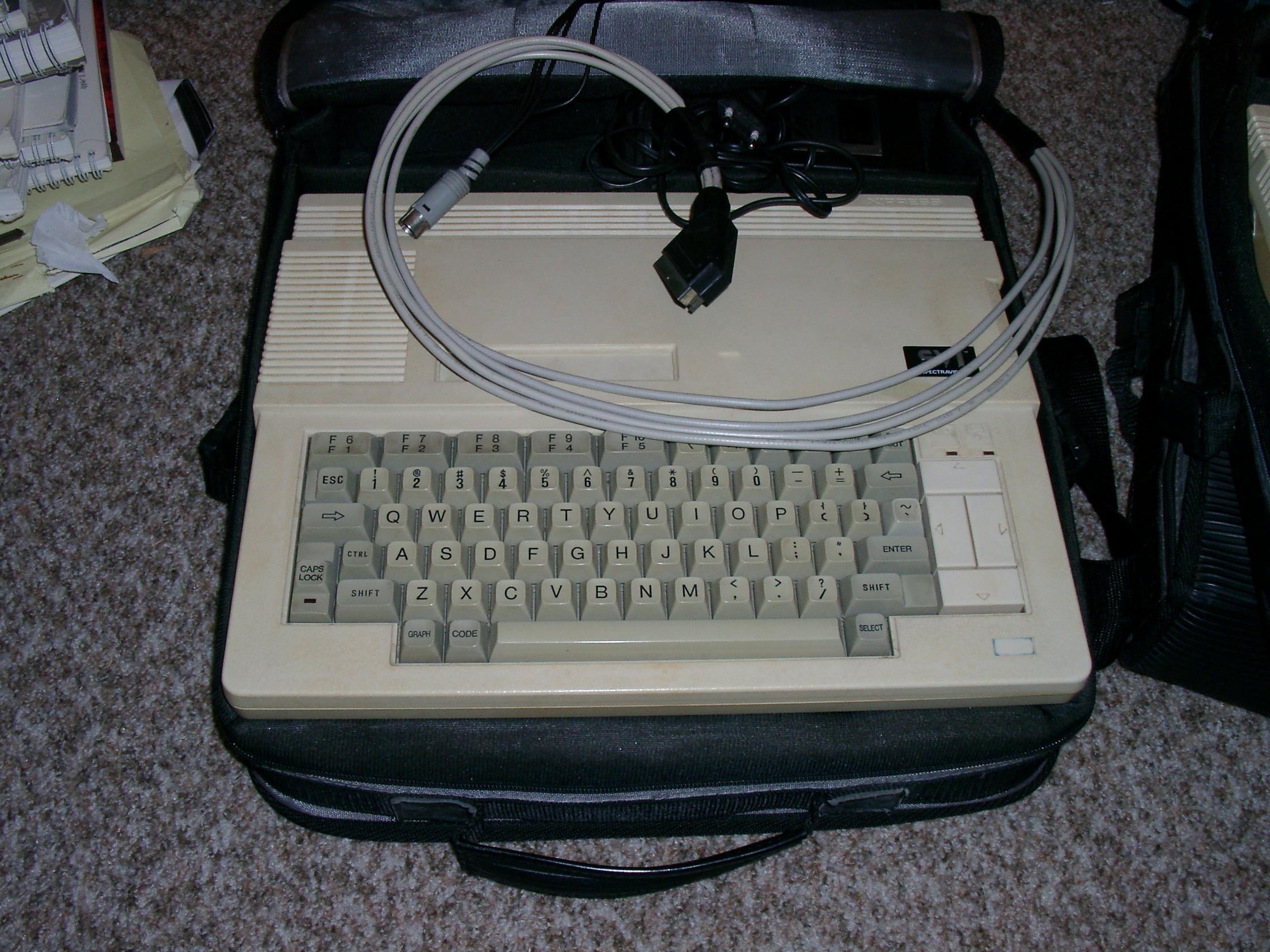
In 1986 the second machine, a Spectravideo SVI.738 Xpress entered my home. And that was not only fun, but a real computer: floppy drive, MSX-DOS, CP/M, 80 column screen. A real workhorse, with CP/M and Turbo Pascal! Mostly used with CP/M and a VT100 as console via the serial interface. Enhanced to MSX-2, two floppy drives, RGB output.
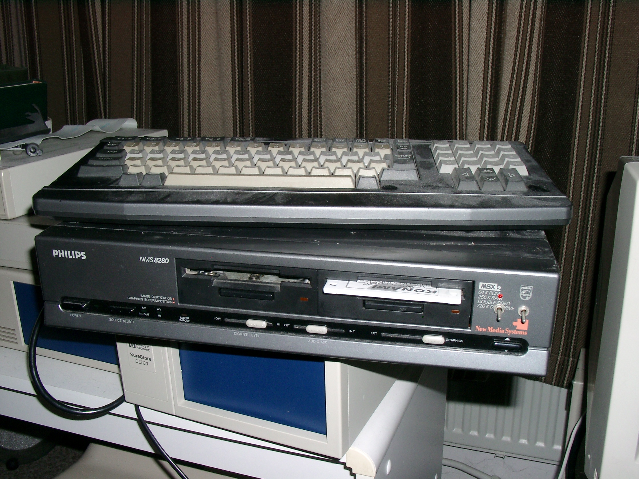
My interest in videoprocessing made me buy the quite expensive NMS8280 in 1992. Enhanced to MSX-2+ with memory mappers, slot expanders, SCSI hard disk interfaces, S-VHS video input/output. An impressive machine, but less a workhorse than I expected it to be. Video processing was very time consuming, I had two Panasonic S-VHS professional recorders, a video mixing tablet and the NM8280. It was not the success I hoped for, that had to wait for Adobe Premiere and full digital video editing with capturing analog video. A stream of IBM PC clones took the place of workhorse the years after and the MSX machines gathered dust.
Here I show scans and software for MSX I have personally scanned and dumped from floppy. A small subset and in no way intended to be the MSX Info Pages, just my scans and dumps.
History of MSX Info Pages
Around 2000 I started collecting retro home computers, MSX and many other 8 bit CPU based small computers. And developed the MSX Info website full with documents and software, initialy on the machines I owned like SVI.738 and NMS8280 and the interfacing with electronics. The house quickly filled with hundreds of machines, the website exploded with scanned documents and files.
All things come to an end, in 2012 I started selling the huge collection to enable a move to a smaller place and recover some of my investments. So in 2015 all was gone, the photos and files are all that is left.
I continued to update the website MSX Info Pages with what was sent to me or collected from the internet. In 2019 I decided to stop also with the website, thanks to the continued leeching and deep-linking by the unresponsive maintainers of msx.org. The quality content of the website, my pages, my scans, are what made the MSX Info Pages fun for me, not being used as free file storage to by the wiki maintainers of msx.org. So be it. The MSX scene is often an unpleasant environment.
MSX Info pages are closed as of April 2, 2019
A static copy, thanks to Arnaud de Klerk aka TFH, is available at at TFHs server.
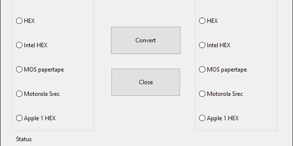
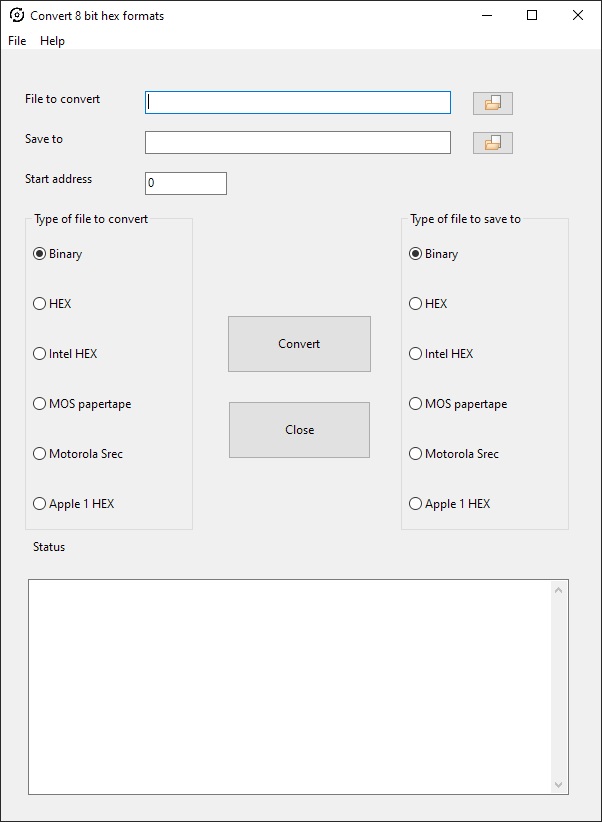
A program to convert between hex or binary files for 8 bit systems with a 64K address space. V2 adds the Wozmon Apple 1 format and allow multipart Intel Hex, MOS Papertape and Motorola S records.
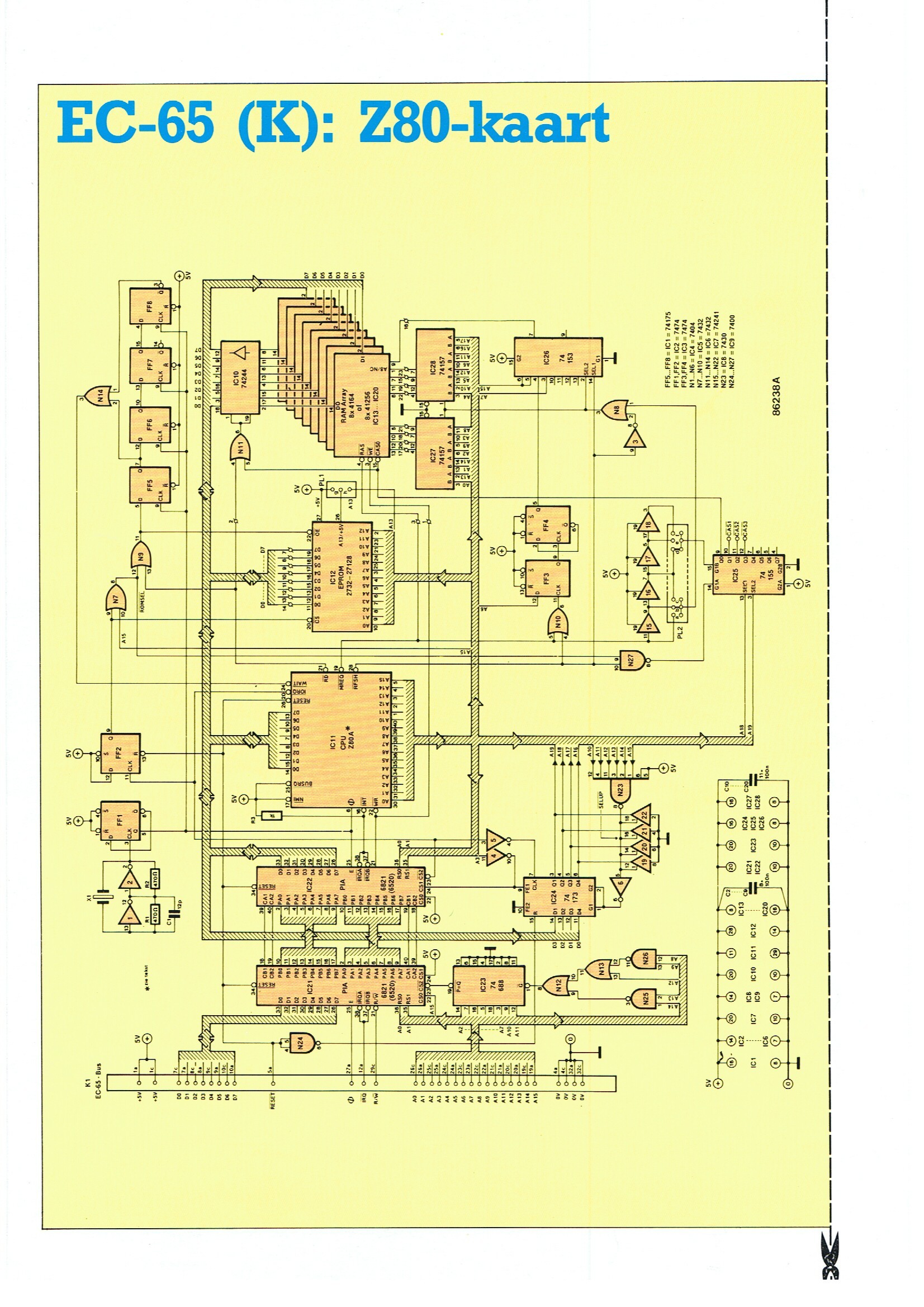
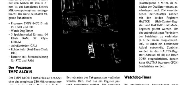
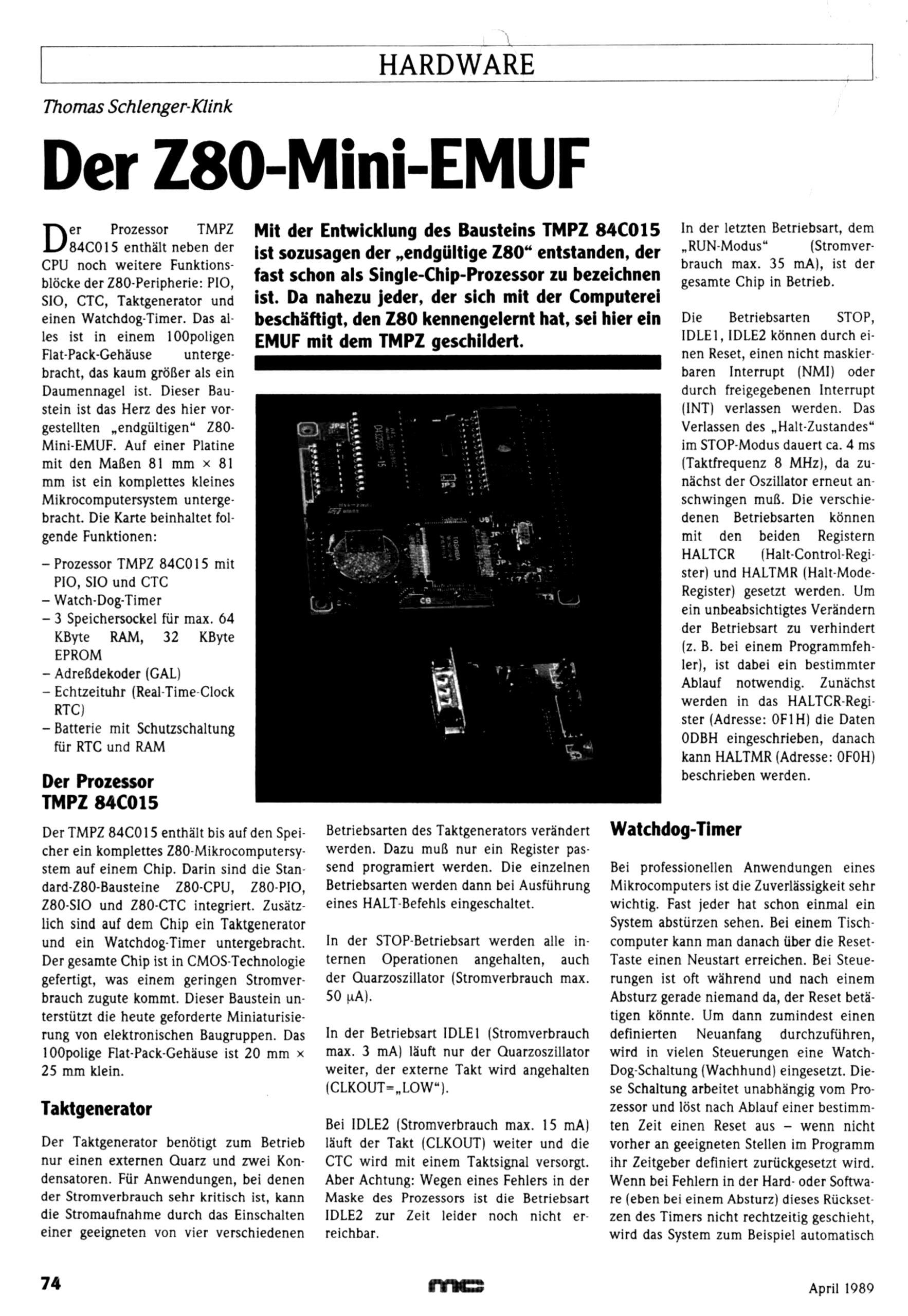
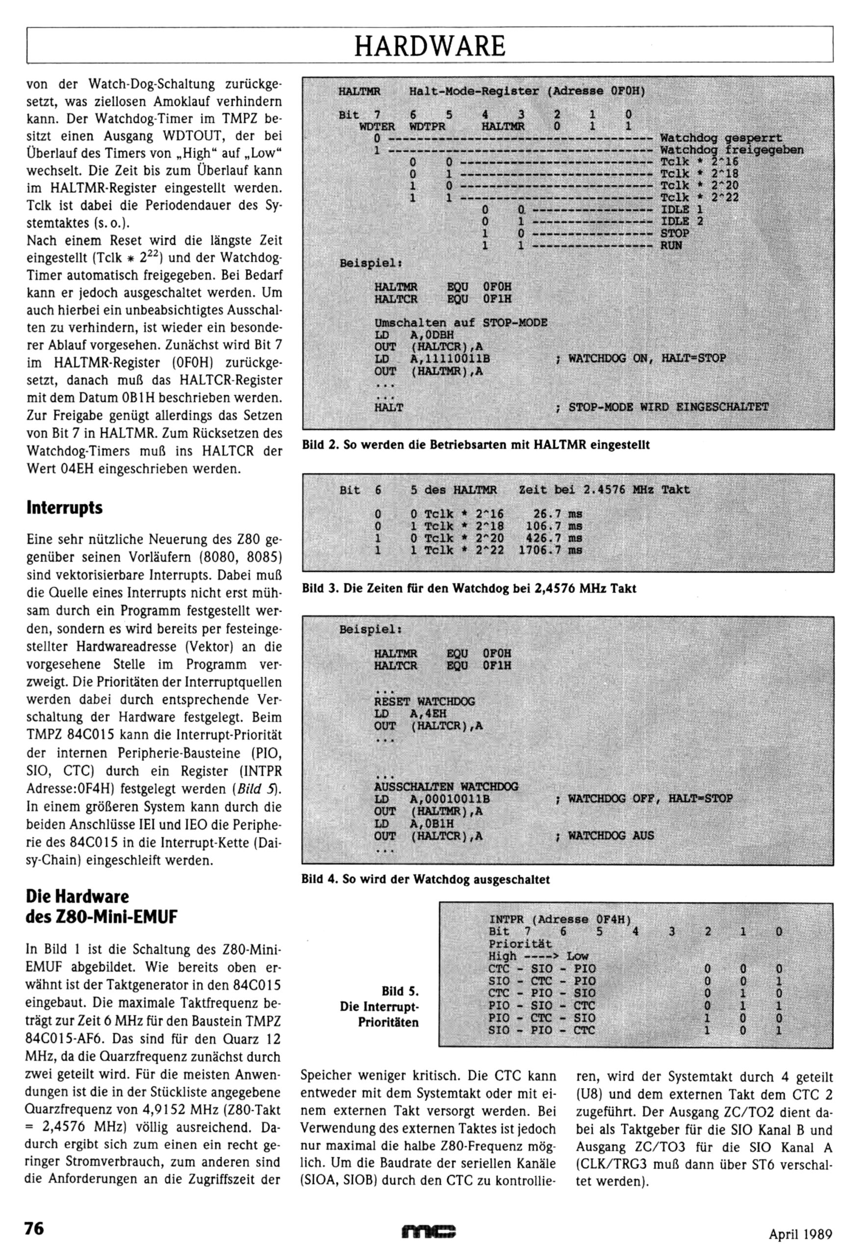
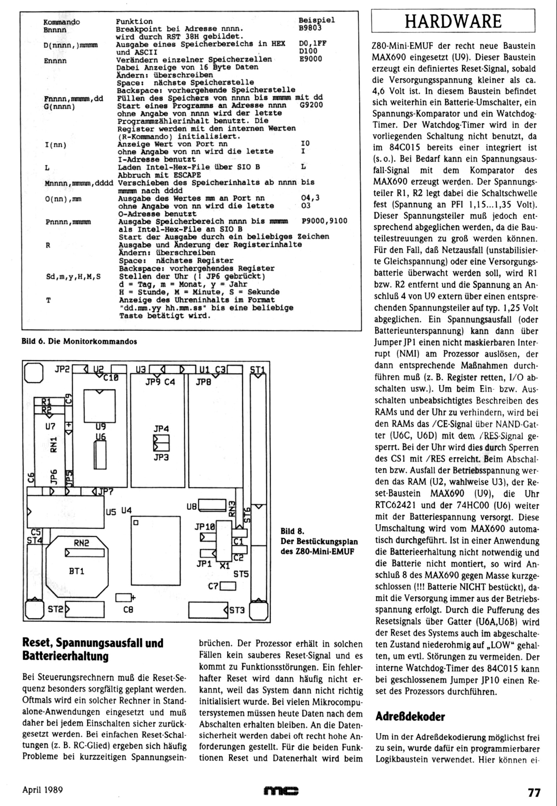
Based on the TMPZ84C015, a Z80 system-on-a-chip ‘Der Z80-Mini-EMUF was published in MC April 1989.
The EMUF family lived on!
Thanks to Bram Prosman for the scan.