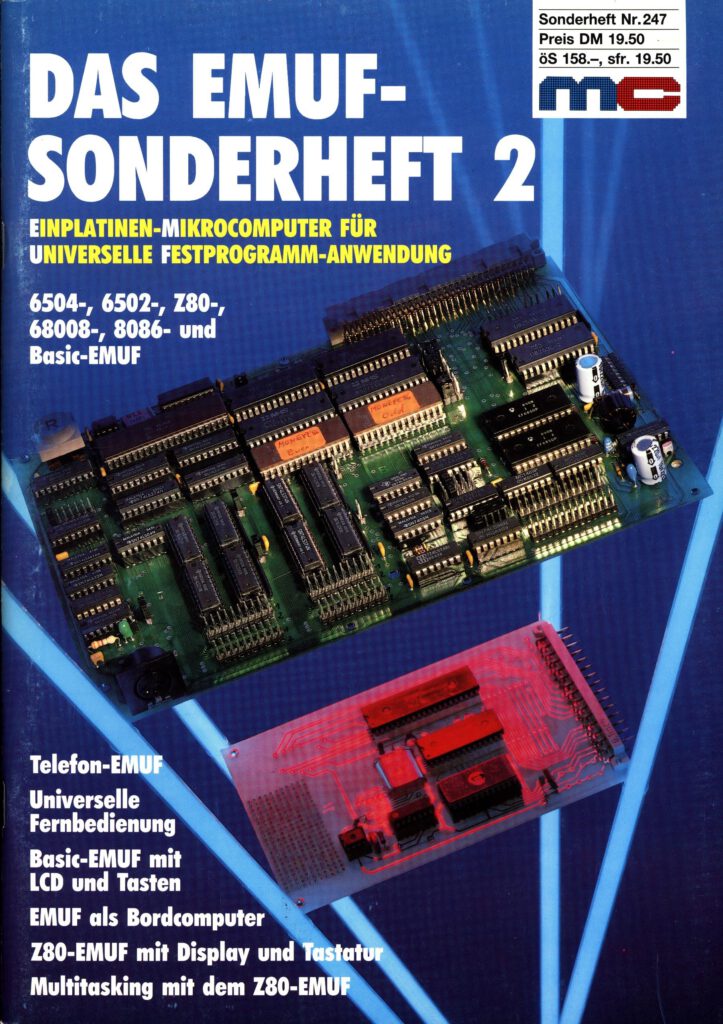
Thanks to Mathias Ohlerich for the scan of the Sonderheft 2
See also:
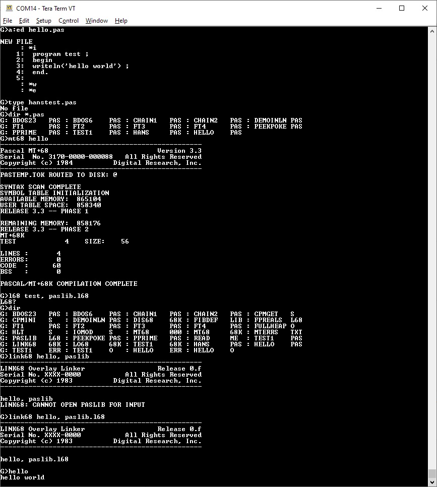
A demo of the new facilities in the KIM-1 Simulator 2.2.1
A demo of the new facilities in the KIM-1 Simulator 2.2.1
Scroll, copy paste of the console.
New versions of KIM-...
KIM-1 connectors: beware the Chinese cheap variants!
The KIM-1 needs 2 edge connectors.
The specifications are: card edge; PIN: 44; 3.96mm
When you search for those, ...
Magazines: Compute! and Compute II
The pages om Magazines had an update.
MICRO has its own page with all Best of MICRO pfds.
Compute! and Compute II ar...
All documents in the MTU pages are now clean and higher quality, about 50 new PDFs.
I got hold a about 10 cm of MTU documents. Several I already had in PDF format, some not available yet.
I took the oppo...