post

Corsham github

Bob Applegate used github repositories to archive and supplement some of his projects.

While this github archive is still up (August 2024), it may go away too.

So here dumps of the repositories. Some of the contents may also show up in the Corsham projects archive pages.

6502 Tiny BASIC
# 6502 Tiny BASIC
This is Bob Applegate’s (bob@corshamtech.com) spin of a Tiny BASIC interpreter for the 6502. It uses an IL approach, like proposed by Dr Dobb’s Journal in the first few issues. This is not fancy, it’s not bug free, and it’s not amazing by any means, but it was fun to write and decent enough to do fun stuff and run demos.

CTMon65
CTMon65 – 6502 monitor

Eagle Libraries
These are libraries used in Corsham Technologies LLC prodcuts (www.corshamtech.com).
# SS-50.lbr
This is for constructing SS-50 and SS-30 compatible boards. It includes both male and female Molex connectors. For constructing plug-in boards using a female connector my suggestion is to place the center of the library part 0.15″ above the bottom of the board.
# S-100.lbr
This is for constructing S-100 boards and is, for now, more of an experimental library rather than something that has any sort of polish about it. Feel free to use but don’t be too disappointed when it does not meet your expectations.

Kicad SS50
# KiCad SS-50 Library from Corsham Technologies, LLC
This is a free to use library that was developed during our creation of
various SS-30/SS-50 boards.

KIM Monitor
# KIM-Monitor
KIM monitor as modified for the Corsham Tech KIM Clone board.

Music Board master
# SS-30 Music Board
This is a rough recreation of the Newtech Computer Systems model 68 music board. No atttempt
was made to make it look exactly like the original, but it is 100% compatible and uses the
same components as the original.

SD Drive
SD Drive Arduino firmware

SD Shield Tester
The SD Shield Tester is a program to test the Corsham Technologies SD Card System shield. This is primarily a manufacturing tool but can be used for general testing. It’s not very useful, but if you suspect an SD Card shield is malfunctioning, this is a way to test it.

xDbg
# xDbg
xDbg is a 65C02 debugger meant to compliment the Corsham Technologies xKIM monitor

xKiM
# xKIM
xKIM is an extended monitor for KIM computer systems. Commonly used in Corsham Technologies KIM-1 add-on boards.
It is a 6502 based monitor which has basic tools as well as some additional commands for working
with the Corsham Tech SD Card system.

xSBUG
xSBUG
This is the Corsham Technologies version of the SWTBUG SBUG monitor for the 6809. It is close to the original but has support for the Corsham Tech SD Card System (emulates disk drives).

xSWTBUG
xSWTBUG
This is a modified version of the SWTPC monitor SWTBUG for use on their 6800 based SS-50 systems. It has additions for the Corsham Tech SD card subsystem and other minor improvements.

post

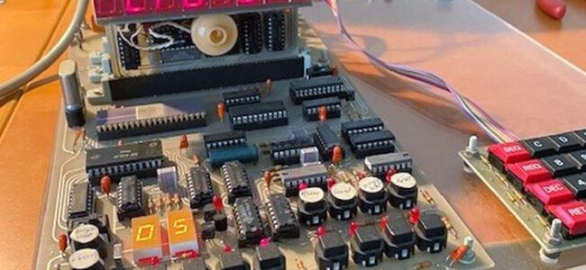
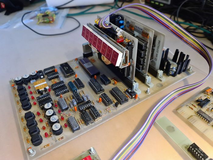
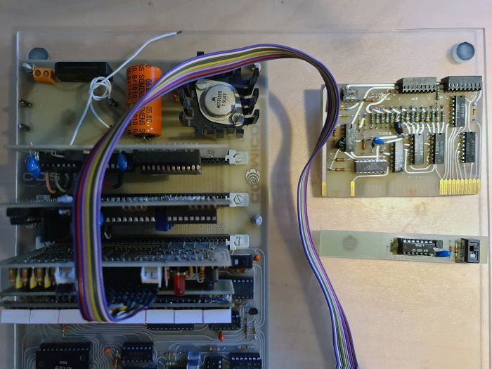
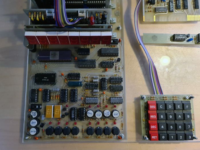
Cosmicos donation

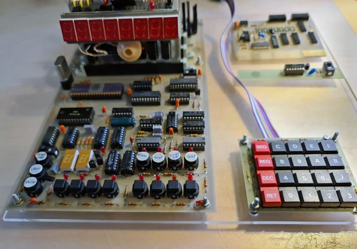
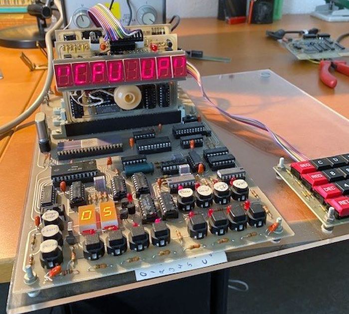
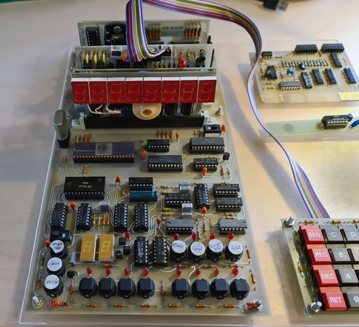
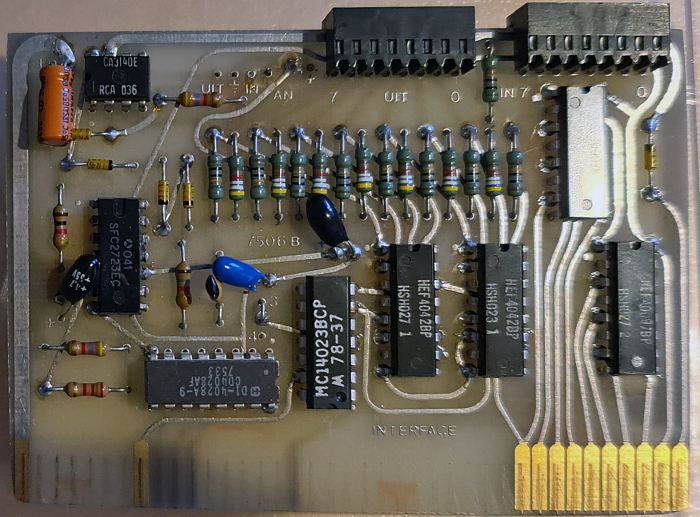
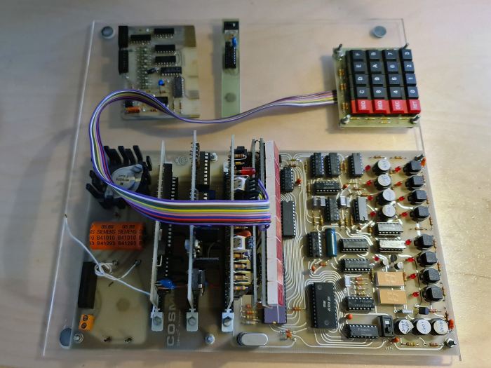
Cosmicos is the name for a SBC around the RCA 1802 CPU. Cosmicos stands for COSMAC MINI COMPUTERSYSTEM.
Published in the dutch magazine Radio Bulletin, developed by the editor (later editor in chief) Bob Stuurman.
The system is loosely based on the Cosmac ELF design. Compatibility with the ELF was later improved in the cassette routine loader, Tom Pittmann’s Tiny Basic and such.

Read all about the Cosmicos here.

H

Prolific USB serial driver misery

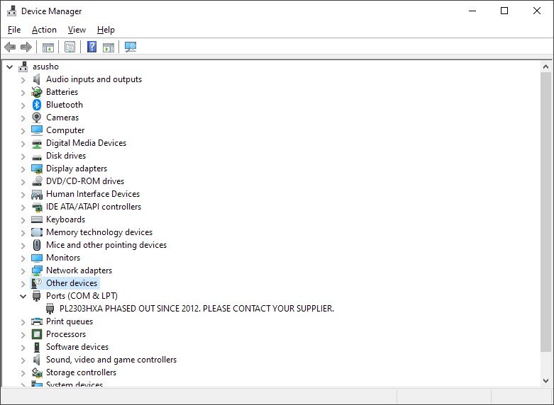
Most of my USB RS232 cables are older, based up the Prolific chipset.

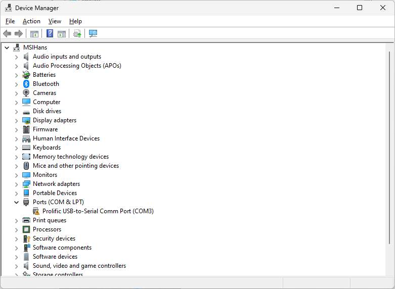
Due to fake chipsets Prolific decided to make their older chipset based cables unusable with their latest Windows device driver, even if the chipset is not a fake and perfectly working.

Waste of good cables! But there is a workaround. Use the oldest driver not doing this destructive activity!

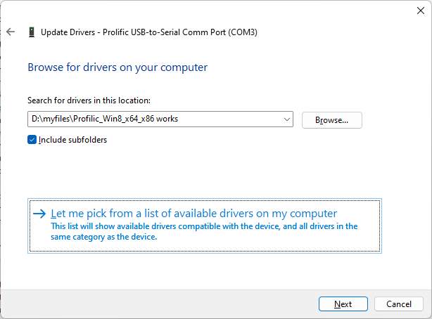
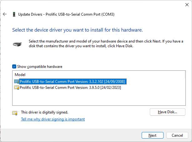
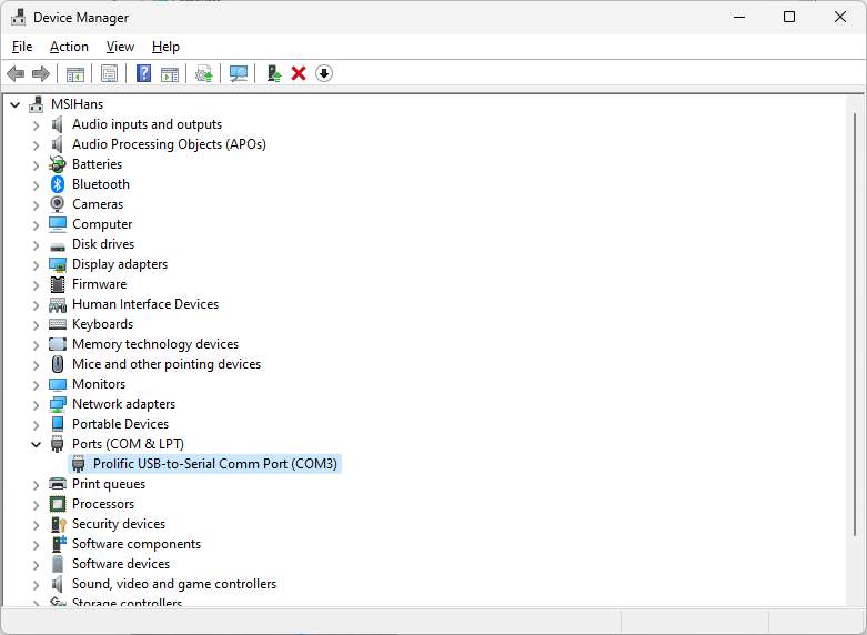
The 2008 driver is in this archive. Unpack in a folder, Update driver, Look on this PC, Have disk, Browse to the folder.
Windows will ‘update’ the driver again, so before using rollback the update in Device Manager.

post

PC utilities updated

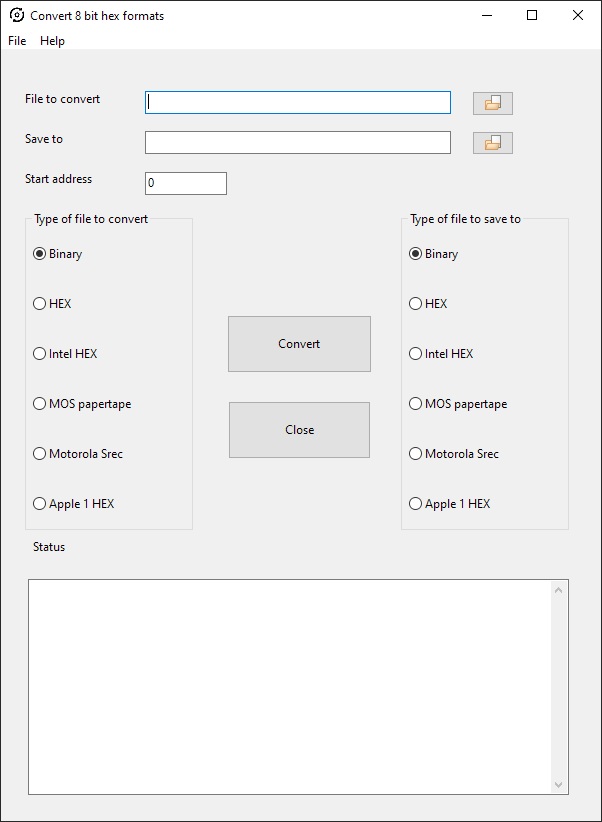
The PC utilities page has seen an update of th4 Conversion hex formats utility.

Programs to manipulate the binary and hex formatted files of interest for SBC owners. Intel hex, MOS papertape, Motorola S-record, binary, hex conversion fort eh 8 bit world.
Runs on Windows, Linux, Mac due to Lazarus and Freepascal. Source included.

post

FABGL library serial and development board

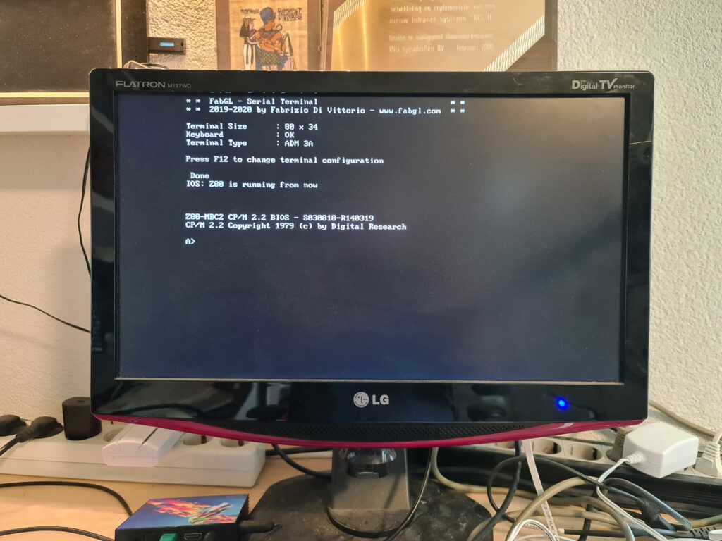
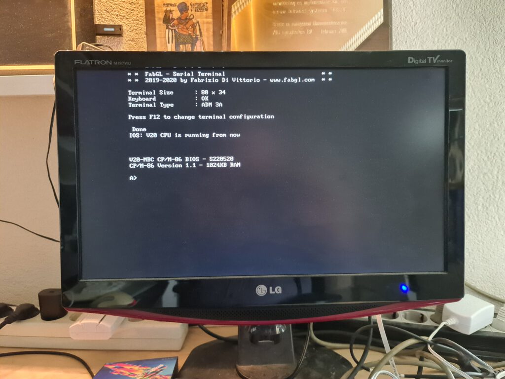
A page dedicated to the FABGL library and baords and how I use it for serial terminal emulation and CP/M emulation (Altair 8800 and CP/M 3 multitasking, IBM PC coming).

FABGL terminal emulator and CP/M

Most SBC’s have a serial interface to work with the computer, using either a RS-232-C compatible interface with a DB-9 connector or more often the TTL interface with pin connector.
A VT100 ANSI termainal emulation is ideal for these machines, whether from a PC or standalone. Teraterm or Minicom are fine examples on Wondows and Linux, with the possibility to transfer data into the SBC’s.

To use the SBC standalone a video terminal is a good solution, cheap, with mostly a monitor with VGA and a PC keyboard, often PS/2.
Examples are the ASCII Video Terminal or the Raspberry PI (any, Zero is low cost) with PIGFX or ESP32 absed, the subject of this page: FABGL software and hardware.

FabGL is mainly a Graphics Library for ESP32. It implements several display drivers (for direct VGA output and for I2C and SPI LCD drivers). FabGL can also get input from a PS/2 Keyboard and a Mouse. ULP core handles PS/2 ports communications, leaving main CPU cores free to perform other tasks. FabGL also implements: an Audio Engine, a Graphical User Interface (GUI), a Game Engine and an ANSI/VT Terminal. .

VGA output requires a digital to analog converter (DAC): it can be done by three 270 Ohm resistors to have 8 colors, or by 6 resistors to have 64 colors. There are several fixed and variable width fonts embedded. Unlimited number of sprites are supported. However big sprites and a large amount of them reduces the frame rate and could generate flickering. When there is enough memory (on low resolutions like 320×200), it is possible to allocate two screen buffers, so to implement double buffering. In this case primitives are always drawn on the back buffer. Except for double buffering or when explicitly disabled, all drawings are performed on vertical retracing (using VGA driver), so no flickering is visible. If the queue of primitives to draw is not processed before the vertical retracing ends, then it is interrupted and continued at next retracing.

There is a graphical user interface (GUI) with overlapping windows and mouse handling and a lot of widgets (buttons, editboxes, checkboxes, comboboxes, listboxes, etc..).

Finally, there is a sound engine, with multiple channels mixed to a mono output. Each channel can generate sine waveforms, square, etc… or custom sampled data.
Audio output, like VGA output, is generated using DMA. CPU just mixes audio channels and prepares waveforms.

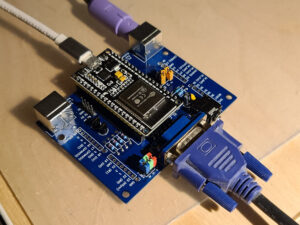
FabGL development board
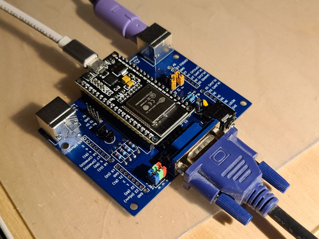
FabGL development board from fabgl on Tindie

This is the reference board to develop and make new experiments with theE FabGL graphic library, which includes VGA output, Audio output, PS/2 Mouse and Keyboard input, Micro SD socket and Arduino style stackable headers.

  • three jumpers to select colors count (8 or 64).
  • 5V logic level converter to have 5V compatible serial port. This is configurable (and be disabled) using jumpers (see UART PATH) allowing TX on GPIO2 or GPIO12 and RX on GPIO34. TX must be disconnected when programming the board.
  • additional four pins header with RX (5V), TX (5V), GND and VCC (5V).
  • PS/2 port pullups connected to 3.3v instead of 5V to reduce ADC noise.
  • Includes PCB, ESP32-WROOM-32 and all required components and connectors already assembled.

Having the SD card connector makes extra things possible, like the Altair8800 and otrh CP/M emulator, see below.

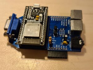
FabGL Terminal

FabGL Terminal from fabgl on Tindie

This is a serial terminal based on FabGL library.

  • Supports following terminal types: ANSI, VTxxx, ADM 3A, ADM 31, Hazelttine 1500, Osborne, Kaypro ant VT52.
    German, Italian, UK and US keyboard layouts.
  • Configurable 5 Volts serial port.
  • Two PS/2 ports for Keyboard and Mouse.
  • One VGA output, up to 64 colors.
  • One audio out (line level, not amplified).
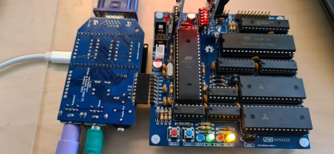
  • Powered from USB port can power a Z80 board, like the MBC2.
  • Bottom 8 PINs connector, with RX, TX, GND, 5V signals (also compatible with MBC2-Z80 board).
  • Upper 8 PINs connector 6 GPIOs (3.3V volts).
  • Preprogrammed with FabGL Serial Terminal, but reprogrammable with any compatible FabGL program. For example you can run VIC-20 emulator with this board.
  • Can be connected to a 3.3V device (like Raspberry pi) using IO2 pin as TX

While the library may look very sparsely documented, there is a large collection of youtube tutorials and examples available made by the author:

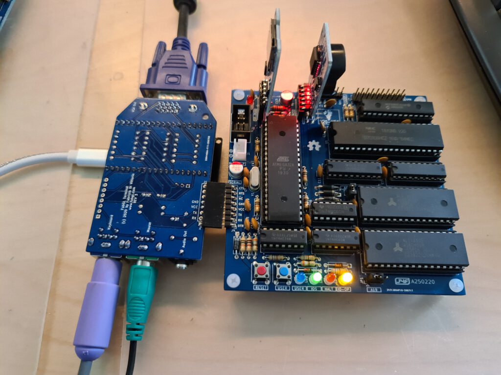
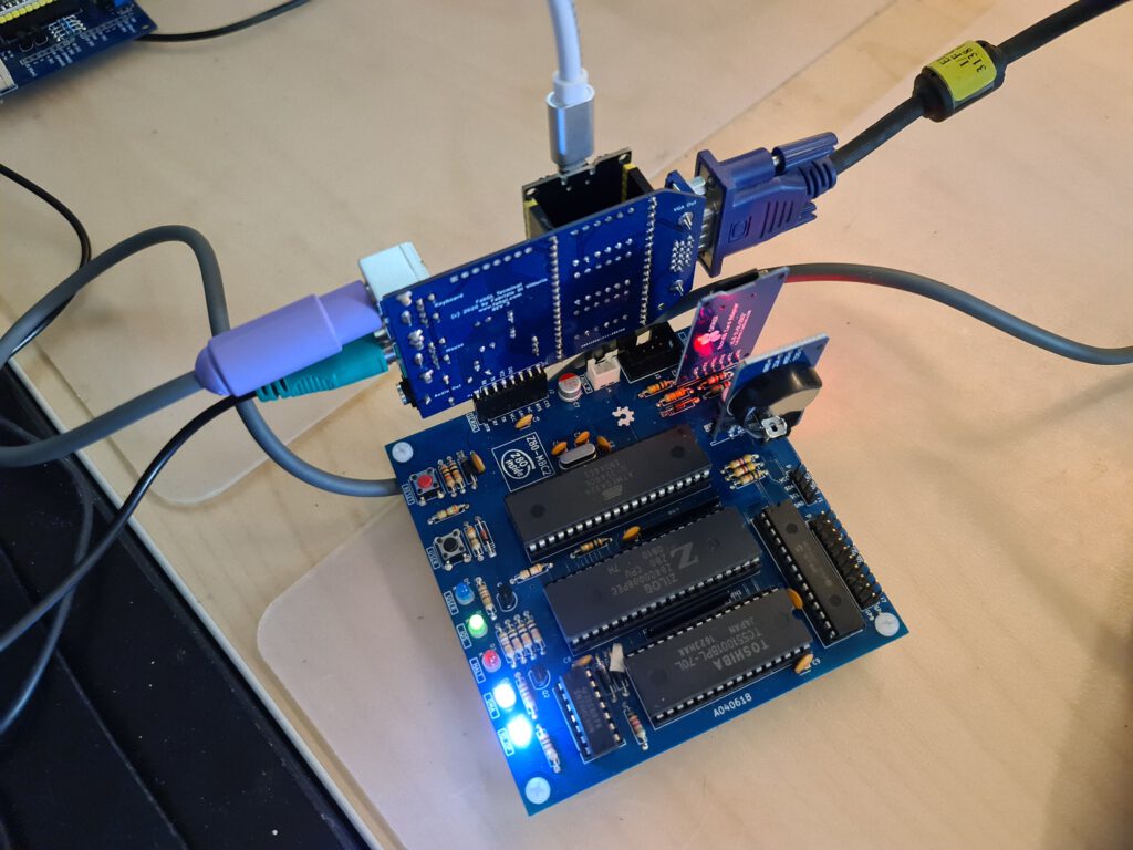
I use the serial terminal on my MBC-2 and MBC-V20, it is a “plug on” solution and functions fine with a real PS/2 keyboard.

FABGL serial with V20-MBC

FABGL serial with MBC-2

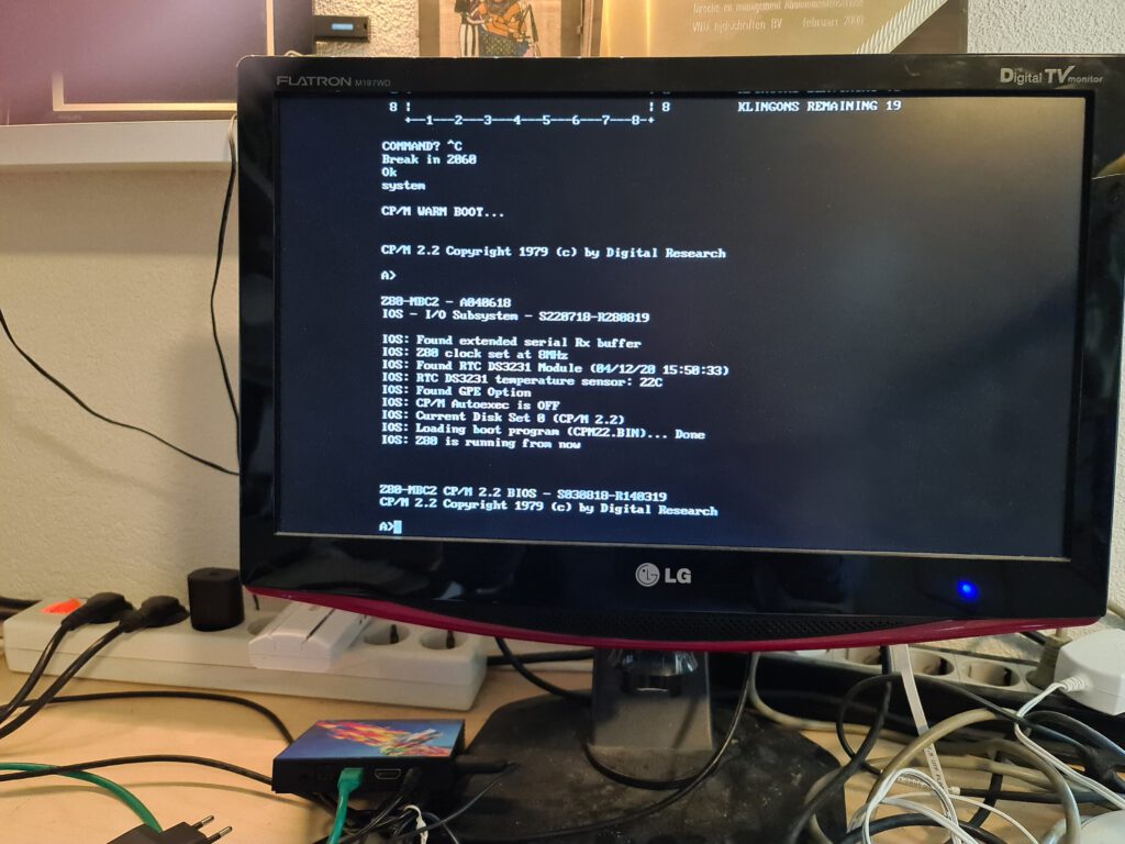
CP/M emulator

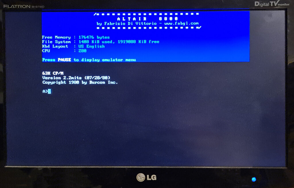
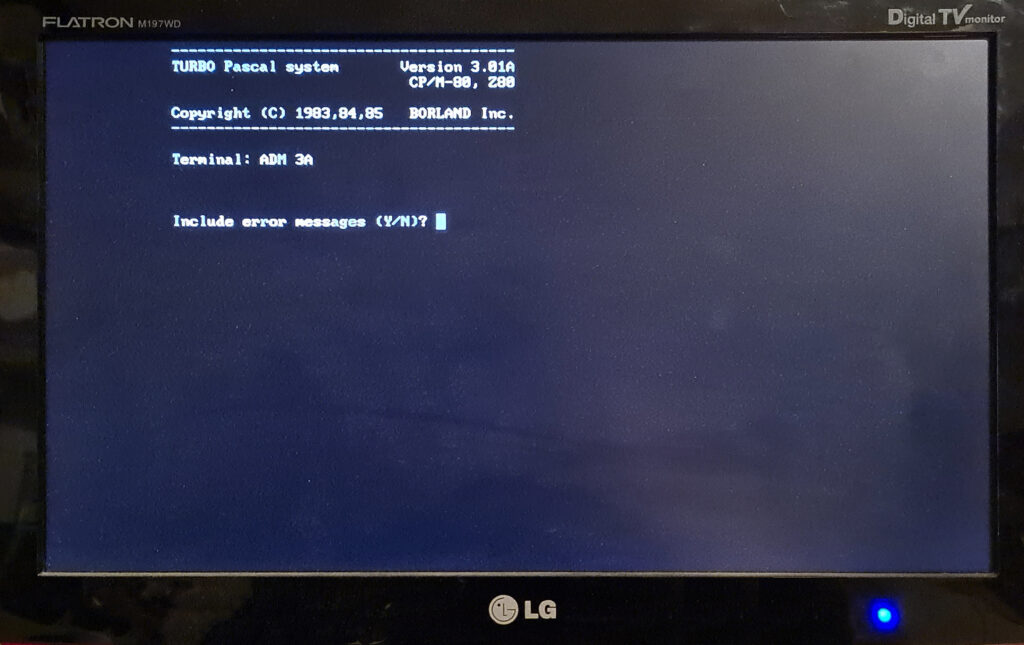
The ESP32 is a powerful system, and running a CP/M emulator is withingn its capabilities. The FABGL library offers two CP/M emulators, an Altair emulator and a CP/M 3

The CP/M examples are not that difficult to install.

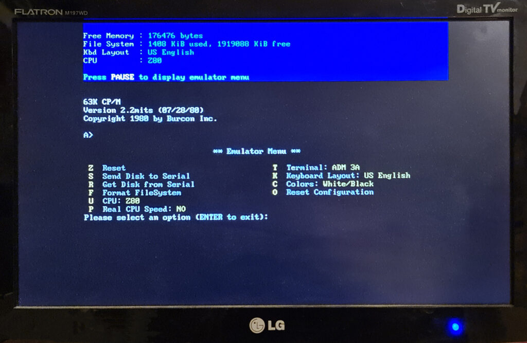
For the AltairDOS version it is wise to study the emu menu. It has an option to Get or Send a disk to serial, you need the Python programs transdisk.py (and transfile for xmodem trasnfer) on the PC side for that.
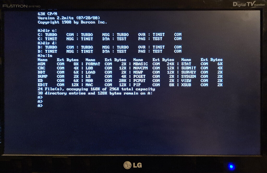
Two disks are standard, two more are possible, stored on the SD or the ESP32 Flash SPIFFS. Use Format File system from the menu, and after rebooting, you have to create the CP/M filesystem, running “FORMAT” command. Then press “C” or “D” (uppercase). At “COMMAND” prompt write “FULL” and press enter. Now press “C” (still uppercase). You should see tracks formatting and verifying. Press “S” to exit.

The AltairDOS in this emulation is based upon the Burcon CP/M implementation, Here the original CP/M and Sysgen disks with documentation (for SIMH).
CP/M for the Altair 8800 and Altair Floppy Drives

CP/M 3 multitasking

post

NOP testers

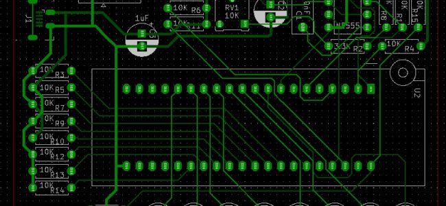
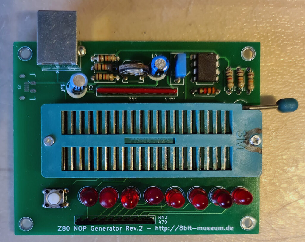
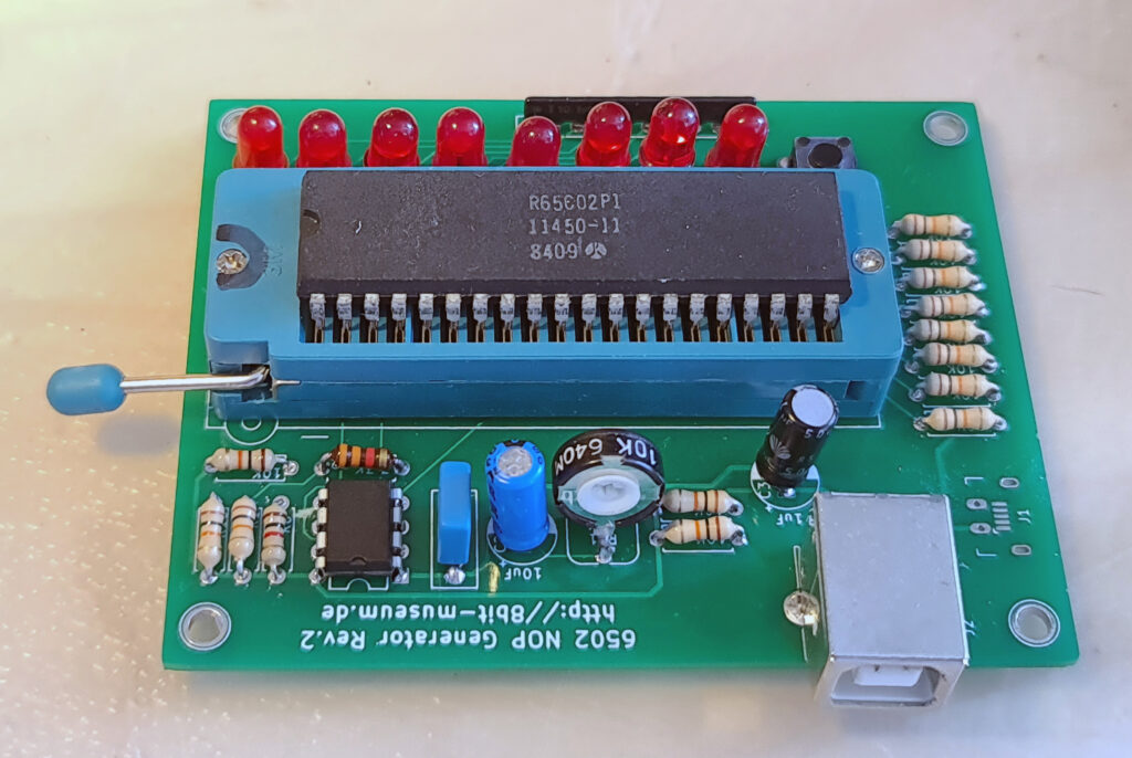
I built two NOP testers, simple standalone devices to do a simple sanity check test if this CPU is at least doing something that can be expected. Not a thorough test of speed, instructions, all address lines or datalines or control lines. 

Retro Chip Tester

See 8bits-museum.de

The Retro Chip Tester was developed to test “old” memory chips from the 1970s and 1980s, which are often no longer recognized by today’s programming devices.

January 2021: I am building one!

  • PCB ordered and received from See 8bits-museum.de
  • Parts ordered at Reichelt and received
  • LCD ordered at amazon,de and received

https://youtu.be/OWo2DZXuhMY

Pocketerm

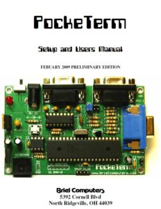
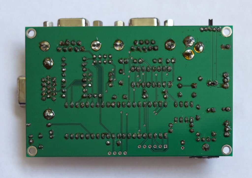
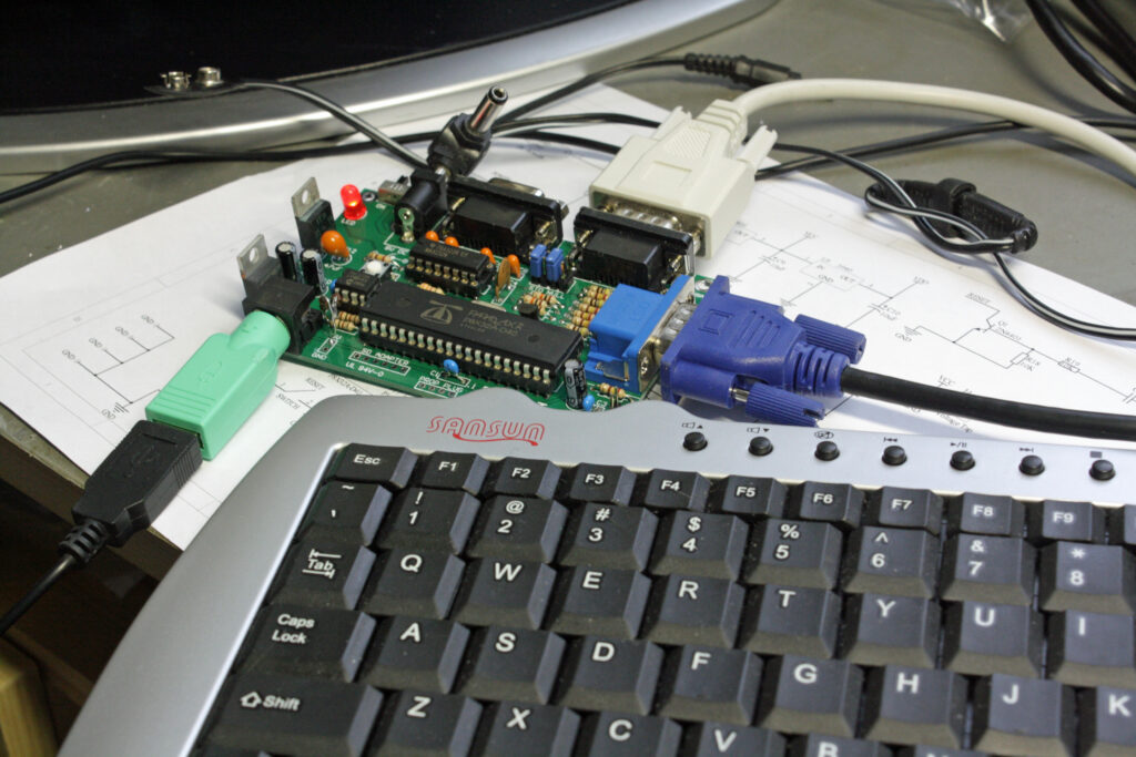
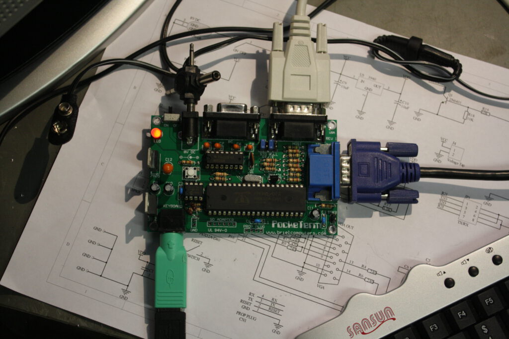
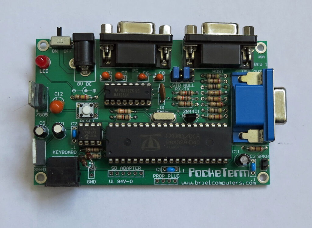
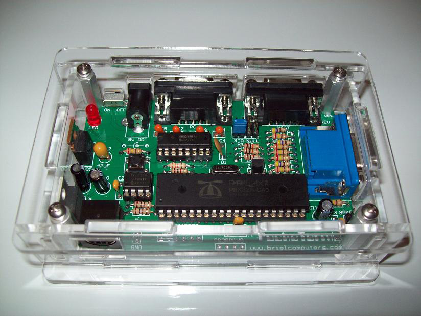
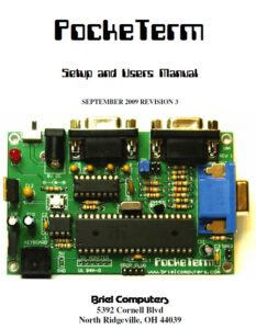
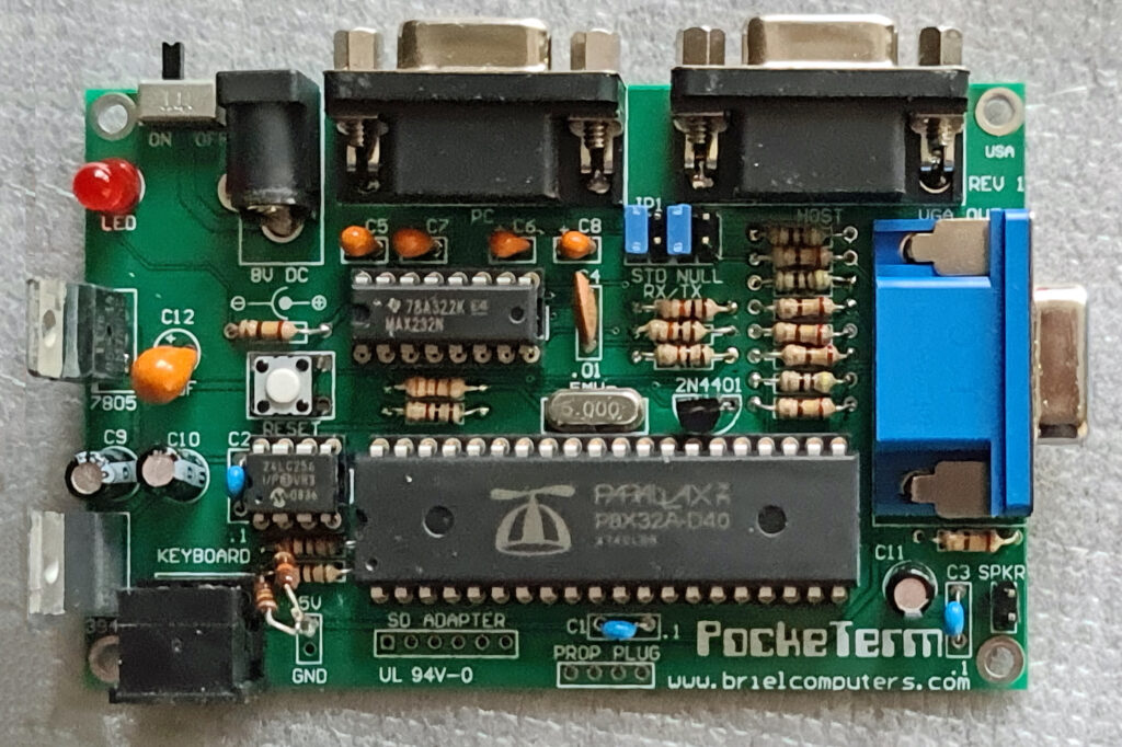
The PockeTerm is a 4″ X 2.5″ single board terminal that uses a VGA monitor and a PS/2 keyboard for its input and output. Dual serial ports gives the user the option of transferring data to/from a PC while still connected to the host device. This terminal was designed to work with vintage computers but is compatible with most systems including Unix and Linux systems. A low cost color choice terminal that has VT-100 compatible commands for controlling cursor and screen functions. Want to program the propeller microcontroller or install an update to the firmware? No problem, just connect the PockeTerm to your PC, run the Propeller Tools software and you can program it from your PC, no expensive Prop Plug required.

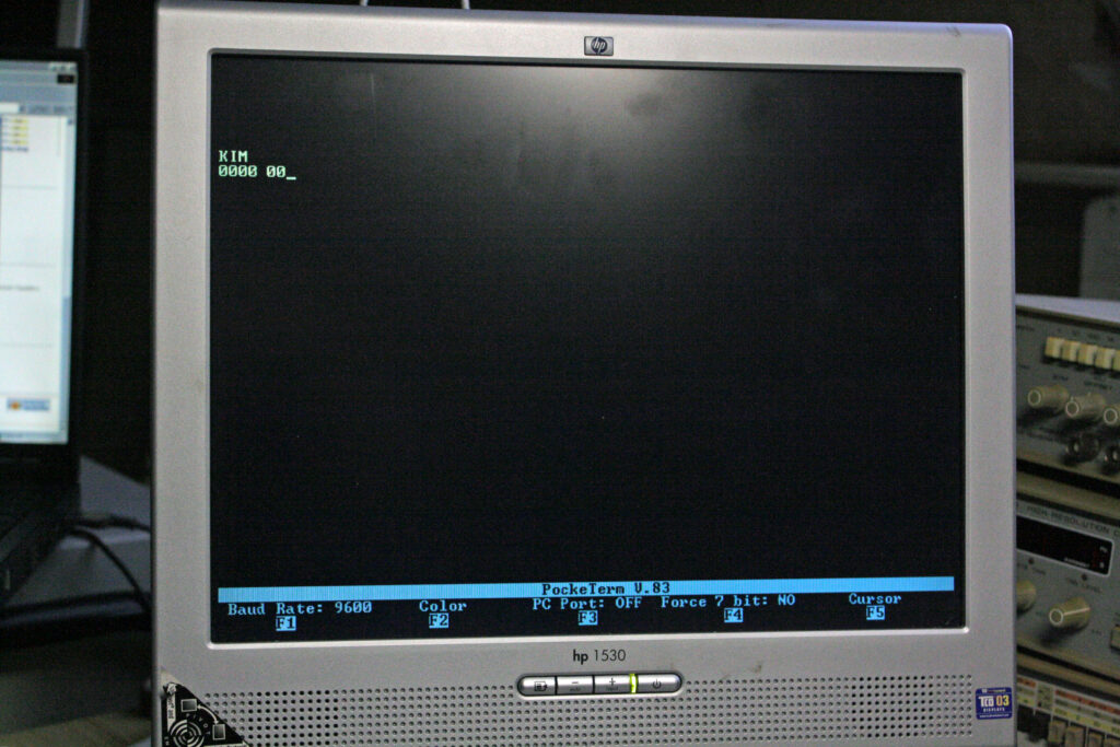
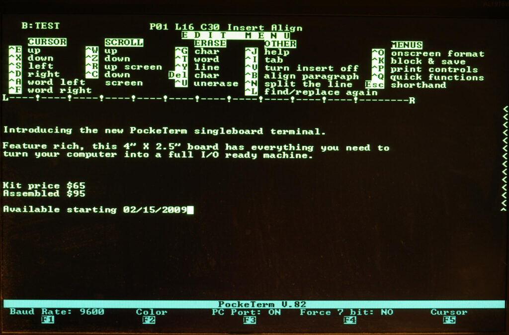
The PockeTerm has a full featured screen with Function key status at the bottom of the screen. Click on the image for a full size photograph of the screenshot.

CTRL-F1 Selects Baud Rate
CTRL-F2 Changes text color of the main display section
CTRL-F3 Turns on/off the 2nd serial port that connects to a PC.
CTRL-F4 Force incoming data to 7 bit ASCII. Strips the 8th bit, required for some systems
CTRL=F5 Change cursor type. Choose from underscore, solid block, or none. Also, choose from blinking or not.
CTRL-F6 Add line-feed to carriage returns

Documents

Pocketerm Setup and Users Manual 2009
Pocketerm Setup and Users Manual V3 2009
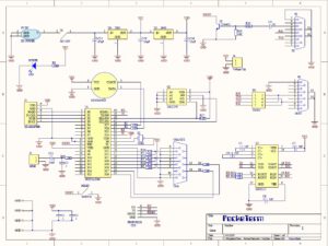
Pocketerm Circuit diagram
Pocketerm Bill Of Materials
Pocketerm Firmware
Pocketerm CD

PS/2 keyboards

I have succesfully assembled the kit, the manual guided me just fine through the steps. Took me just over an hour.
The PockeTerm worked right away. Thanks to mfortuna’s tip, put jumpers in 1&2 and 5&6, and testing is independent of cables and computers to connect.

A standard keyboard with PS/2 worked. What did not work was my mini-USB keyboard (standard PC keyboard without numerical pad, and smaller size, like notebook keyboards) connected via an USB to PS/2 converter. The USB keyboard is ok, works with the PC’s and the Apple 1 kits via the USB-PS/2 dongle. I bought it because the smaller size looks better with the small computers and takes less desk space With the scope I found the PS/2 clock/data line (cant remember which one), to be open, as if nothing connected. So something is missing to make the USB device come alive. I googled around and found this: http://www.parallax.com/Portals/0/Downloads/docs/prod/edu/28060-PS2Adapter-v1.0.pdf
In it I saw a schematic how to connect a Parallax mini PS/2 keyboard, and it was different from the PockeTerm PS/2 interface. It has additional 10k pull-ups connected to the PS/2 clock and data. I soldered in the two 10k’s and the mini keyboard came alive!

Program the Propeller Notes by Vince Briel

  1. Go download propeller tools from parallax here: http://www.parallax.com/Portals/0/Downloads/sw/propeller/Setup-Propeller-Tool-v1.2.7-(R2).exe
  2. Install propeller tools
  3. Place the firmware directory from your PockeTerm CD onto your hard drive here:
    C:\program files\parallax inc\propeller tool v1.2.7 (r2)\
  4. Connect your PockeTerm to the RS232 port labled PC and turn on your PockeTerm.
  5. Under the propeller tools program click on the section File and find the firmware directory you just copied onto your hard drive and select the file
    PockeTermV.905.spin
  6. Press F11 on your PC keyboard and the propeller tools will compile and attempt to find a Propeller chip connected to a serial port on your PC. If your
    connection is good it will program the RAM first on your Propeller chip then program the EEPROM.

The PockeTerm makes a really good development board for learning how to program the Propeller chip. For more information on programming the Propeller,
please visit the Parallax forums here: http://forums.parallax.com/forums/default.aspx?f=25
The above steps will program the Propeller with the code that is now resident on the EEPROM onboard the PockeTerm. Change step 3 to the location of the program you wish to insert onto the PockeTerm.


Other retro articles