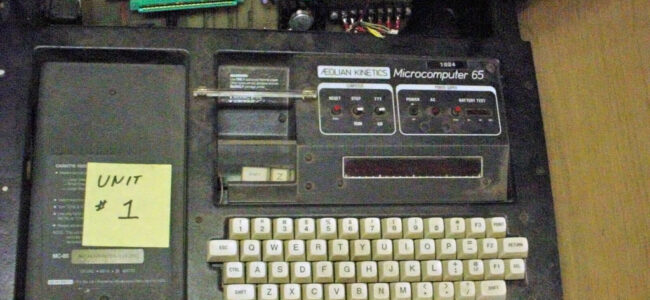
Michael Doornbos (of https://imapenguin.com/) posted two “10 PRINT” articles for our beloved small 6502 SBC’s.
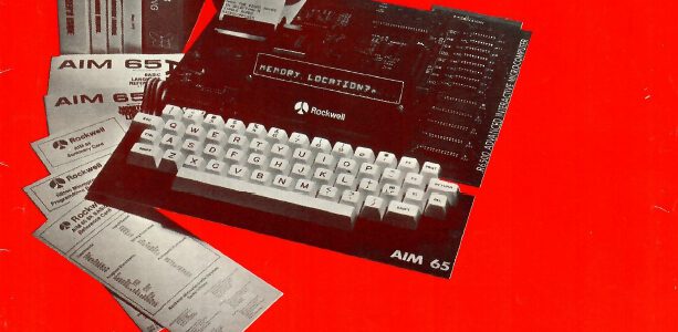
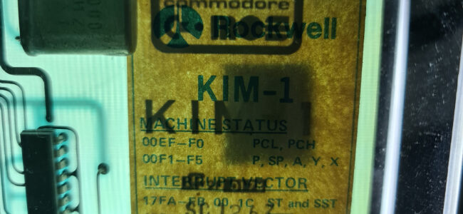
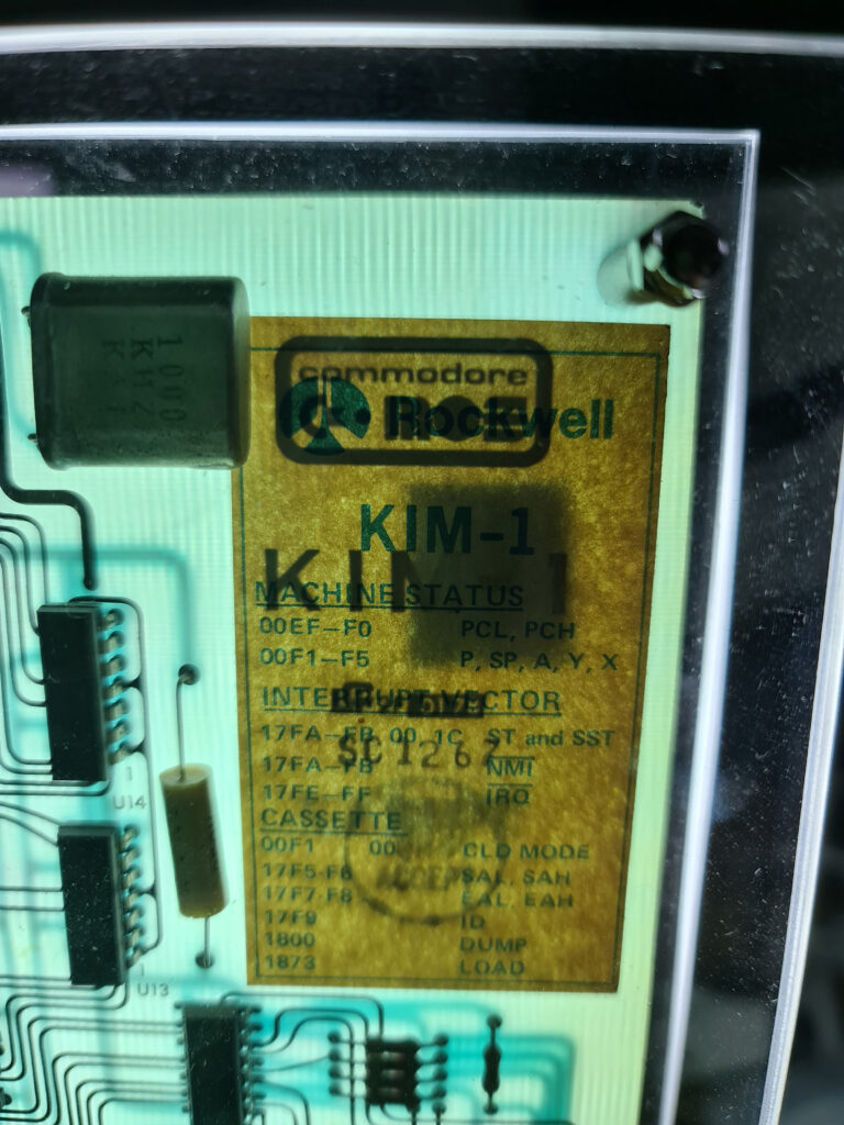
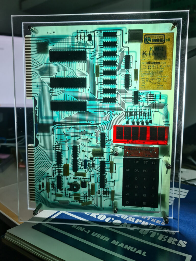
The KIM-1 version displays on the seven segment LED displays. The AIM 65 prints it on the thermal printer.
KIM-1 version of 10 PRINT in BASIC and assember
10 PRINT CHR$(47+INT(RND(0)*2)*45);:GOTO 10
; BY MICHAEL DOORNBOS MIKE@IMAPENGUIN.COM; 2025
; SOFT START AT $0200
; THIS PROGRAM GENERATES A RANDOM PATTERN OF SLASHES AND BACKSLASHES
; AND DISPLAYS IT ON THE KIM-1'S 7-SEGMENT DISPLAY.
; THE PATTERN SCROLLS TO THE LEFT, CREATING A CONTINUOUS EFFECT.
; A LOT OF THIS CODE IS BORROWED FROM:
; https://netzherpes.de/blog/index.php?entry=KIM-1-scrolltext
; kim_msg.asm
; testing lin2c64 6510 assembler
; using J. Butterfield's scan display from Wumpus
; 01/03/2013 ces
; CONSTANTS FOR 7-SEGMENT DISPLAY CHARACTERS
BACKSLASH .EQU $64 ; BACKSLASH CHARACTER
SLASH .EQU $52 ; FORWARD SLASH CHARACTER
SPC .EQU $80 ; SPACE CHARACTER
; KIM-1 HARDWARE ADDRESSES
SAD .EQU $1740 ; DATA PORT FOR PINS 1-4
SADD .EQU $1741 ; DATA DIRECTION REGISTER A
SBD .EQU $1742 ; DATA PORT FOR PINS 5-6
SBDD .EQU $1743 ; DATA DIRECTION REGISTER B
TIMER2 .EQU $1747 ; OPTIONAL 2ND 6532 TIMER
LOUT .EQU $7F ; SET PINS AS OUTPUT TO LEFT 4 LEDS
ROUT .EQU $1E ; SET PINS AS OUTPUT TO RIGHT 2 LEDS
; ZERO PAGE VARIABLES
SEED .EQU $00D0 ; RANDOM SEED LOCATION
TMR .EQU $00DB ; TIMER COUNTER
PTR .EQU $00DC ; POINTER
XFRHI .EQU $00DD ; USED FOR CHARACTER BUFFER HIGH BYTE
XFRLO .EQU $00DE ; USED FOR CHARACTER BUFFER LOW BYTE
TMP1 .EQU $00DF ; TEMPORARY STORAGE
CBUFF .EQU $00E8 ; CHARACTER BUFFER (6 BYTES)
MSGBUF .EQU $0180 ; BUFFER FOR GENERATED PATTERNS (30 BYTES)
.ORG $0200 ; START OF PROGRAM CODE
MAIN
; CLEAR THE MESSAGE BUFFER FIRST TO PREVENT GLITCHES
LDX #$00
CLRLOOP LDA #SPC ; USE SPACE CHARACTER TO INITIALIZE
STA MSGBUF,X
INX
CPX #$30 ; CLEAR THE ENTIRE BUFFER AREA
BNE CLRLOOP
LDA #$00 ; ADD NULL TERMINATOR AT THE END
STA MSGBUF+23
; INITIALIZE THE TIMER
LDA #$FF ; LOAD MAXIMUM VALUE
STA TIMER2 ; START TIMER
; USE TIMER VALUE AS SEED
LDA TIMER2 ; READ CURRENT TIMER VALUE
STA SEED ; USE AS RANDOM SEED
BNE SEEDOK ; IF NOT ZERO, IT'S FINE
INC SEED ; OTHERWISE INCREMENT TO MAKE NON-ZERO
SEEDOK JSR GENPAT ; GENERATE INITIAL PATTERN
INFINIT LDY #>MSGBUF ; LOAD BUFFER LOCATION
LDA #<MSGBUF
JSR SCAN ; DISPLAY THE PATTERN
; GENERATE NEW RANDOM SLASH AT END OF BUFFER
JSR RANDOM ; GET RANDOM BIT
BCC GENBACK ; BRANCH IF CARRY CLEAR (50% CHANCE)
LDA #SLASH ; FORWARD SLASH
JMP STORE
GENBACK LDA #BACKSLASH ; BACKSLASH
STORE STA MSGBUF+22 ; ADD NEW CHARACTER TO END OF BUFFER
; SHIFT BUFFER LEFT ONE POSITION (SCROLL EFFECT)
LDX #$00 ; START AT FIRST POSITION
SHIFT LDA MSGBUF+1,X ; GET NEXT CHARACTER
STA MSGBUF,X ; STORE IN CURRENT POSITION
INX ; MOVE TO NEXT POSITION
CPX #$22 ; CHECK IF WE'RE AT END OF BUFFER
BNE SHIFT ; CONTINUE IF NOT AT END
; ENSURE NULL TERMINATOR IS ALWAYS PRESENT
LDA #$00
STA MSGBUF+23
JMP INFINIT ; LOOP FOREVER
; GENERATE INITIAL PATTERN BUFFER WITH RANDOM SLASHES
GENPAT LDX #$00 ; START AT FIRST POSITION
GPLOOP JSR RANDOM ; GET RANDOM BIT
BCC GBACK ; BRANCH IF CARRY CLEAR
LDA #SLASH ; FORWARD SLASH
JMP GSTORE
GBACK LDA #BACKSLASH ; BACKSLASH
GSTORE STA MSGBUF,X ; STORE IN BUFFER
INX ; NEXT POSITION
CPX #$17 ; CHECK IF BUFFER IS FULL
BNE GPLOOP ; CONTINUE IF NOT FULL
LDA #$00 ; ADD NULL TERMINATOR
STA MSGBUF+23 ; AT END OF BUFFER
RTS ; RETURN
; RANDOM NUMBER GENERATOR (8-BIT LFSR)
RANDOM LDA SEED ; LOAD CURRENT SEED
ASL ; SHIFT LEFT (C GETS HIGH BIT)
BCC NOEOR ; SKIP EOR IF BIT 7 WAS 0
EOR #$B4 ; APPLY FEEDBACK POLYNOMIAL
NOEOR STA SEED ; STORE UPDATED SEED
RTS ; RETURN WITH CARRY = RANDOM BIT
; SCANNING ROUTINE FROM ORIGINAL CODE
SCAN STY XFRLO ; Y AND A GET LOADED BEFORE JSR TO SCAN
STA XFRHI
LDA #$07 ; INIT SCAN FORWARD
STA TMP1
LDY #$05 ; INIT Y
CONT LDX #$05 ; INIT X
CHAR LDA (XFRHI),Y ; GET CHARACTER
CMP #$00 ; LAST CHARACTER?
BNE MORE ; IF NOT, CONTINUE
RTS
MORE STA CBUFF,X ; STORE CHAR
DEY ; SET UP NEXT CHAR
DEX ; SET UP NEXT STORE LOC
BPL CHAR ; LOOP IF NOT 6TH CHAR
CLD ; BINARY MODE
CLC ; PREPARE TO ADD (CLEAR CARRY FLAG)
TYA ; GET CHAR POINTER
ADC TMP1 ; UPDATE FOR 6 NEW CHARACTERS
STA PTR ; SAVE NEW POINTER
JSR DSPDLY ; DELAY DISPLAY
LDY PTR ; RESTORE POINTER
JMP CONT ; CONTINUE WITH REST OF MESSAGE
DSPDLY LDX #$0A ; SET THE DELAY RATE HERE
STX TMR ; PUT IN DECR. LOCATION
TIME LDA #$52 ; LOAD TIMER
STA TIMER2 ; START TIMER
LITE JSR DISP ; GOSUB DISPLAY RTN
BIT TIMER2 ; TIMER DONE?
BPL LITE ; IF NOT, LOOP
DEC TMR ; DECREMENT TIMER COUNTER
BNE TIME ; NOT FINISHED
RTS ; NOW GET 6 NEW CHARACTERS
DISP LDA #LOUT ; CHANGE LEFT LED SEGMENTS
STA SADD ; TO OUTPUTS
LDY #$00 ; INIT RECALL INDEX
LDX #$09 ; INIT DIGIT NUMBER
SIX LDA CBUFF,Y ; GET CHARACTER
STY $00FC ; SAVE Y FOR MONITOR DISP ROUTINE
JSR $1F4E ; MONITOR ROUTINE - DISP CHAR, DELAY 500 CYCLES
INY ; SET UP FOR NEXT CHAR
CPY #$06 ; 6 CHAR DISPLAYED?
BCC SIX ; NO
RTS
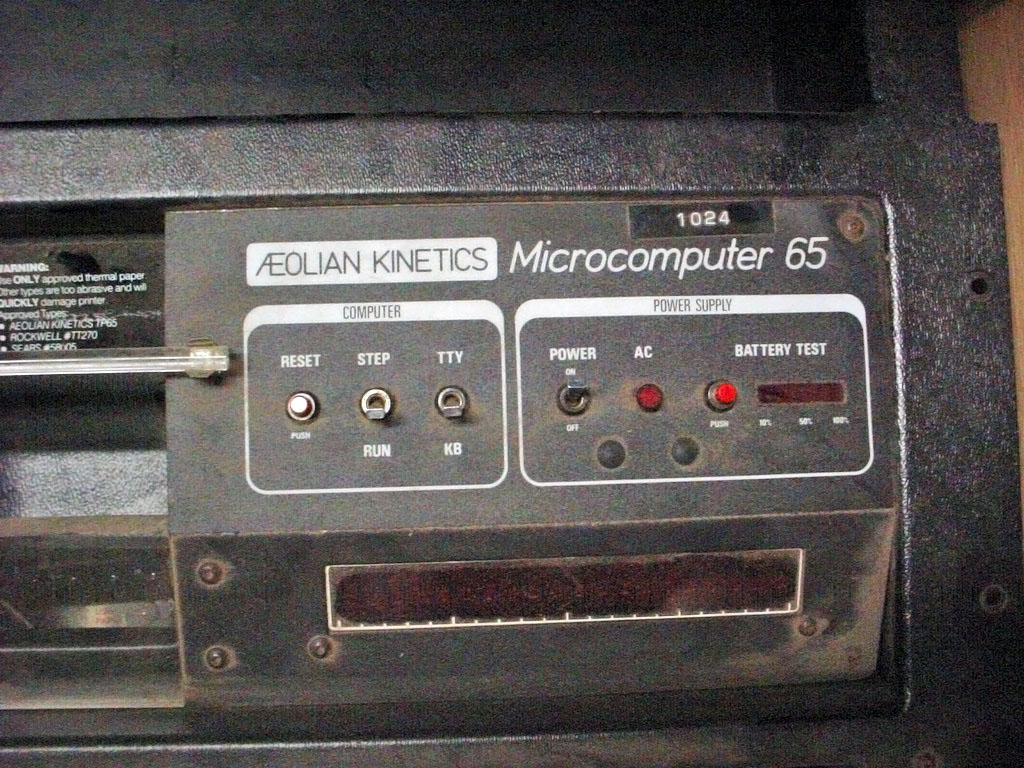
AIM 65 version in BASIC
10 PRINTCHR$(47+(INT(RND(1)*2)*45));:GOTO 10
that print random ‘/’ or ‘\’


