
On the hex keyboard there is an SST switch.
In the ON state one can single step to a program, by pressing GO. After the instruction a the current PC is executed the display lights up again and the keys are active.
All registers are saved in zeropage ready for inspection. Pressing GO again resumes the next instruction with the saved CPU registers.
To use this the NMI vector must be initialized by the user at 17FA and 17FB to 00 and 1C
The instructions how to use this are in Paragraph 5.5 of the User Manual. There it is only described for the LED display and Keyboard mode, but it also works at the TTY interface.
Note that you cannot single step the monitor ROM routines!
Also see this page on debugging on the KIM-1.
How does that work?
The hardware for SST operation is shown in the next figure
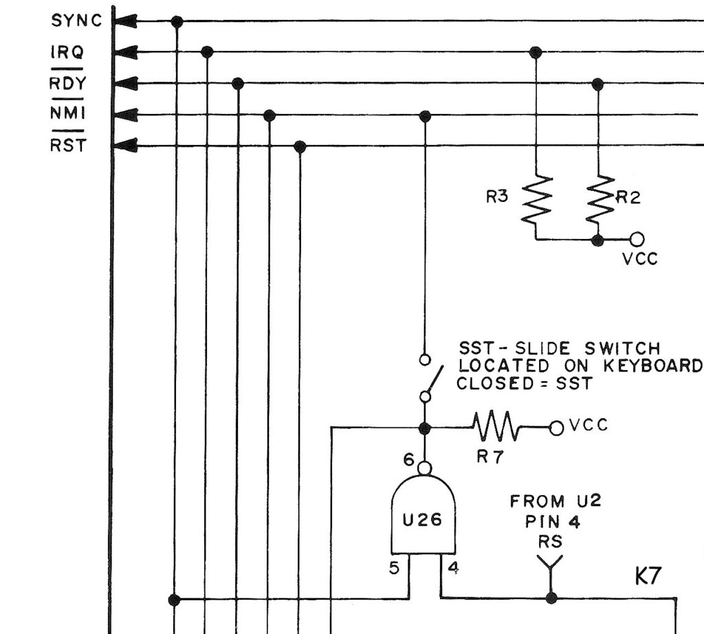
The output of the NAND port 26 is connected to NMI when the SST switch is ON. Input 5 is connected to the SYNC signal of the 6502. SYNC goes high for the first byte of an opcode fetch.
So when an opcode fetch occurs NMI is activated and when the current instruction is finished the NMI handler is invoked.
This means a single step of the CPU!
The other input of the NAND, pin 4, is connected to K7, the chip select line for the KIM-1 monitor ROM in the 6530-002. So NMI is blocked when an opcode is fetched from the KIM-1 monitor, and the keyboard and LED can be active.
This does not work reliable when a 65C02 is used, the SYNC timing is different.
Liu Gang implemented a solution in his PAL-2, using the WDC65C02 variant, for this defect.
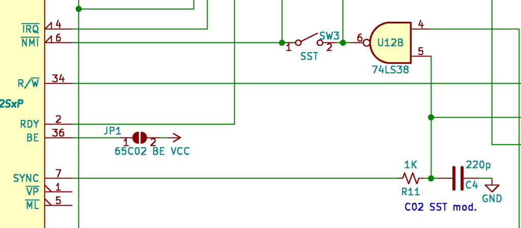
PAL-2 SST NMI SYNC circuit
Bob Applegate also solved this in his KIM Clone revision 4 and 5, also for the WD65C02
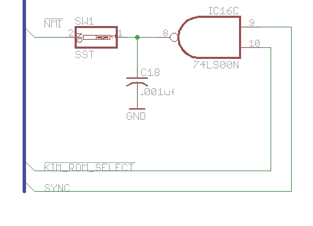
See below for some alternative circuits for the SST NMI creation from SYNC.
NMI, BRK and IRQ handling
The 6502 NMI interrupt is available as ST key on the hex keyboard via a NE556 debounce circuit.
The IRQ line is unconnected (quiet via a resistor pull)
The 6502 vectors are:
1213   1FFA 1C 1C       NMIENT  .WORD NMIT
1214   1FFC 22 1C       RSTENT  .WORD RST
1215   1FFE 1F 1C       IRQENT  .WORD IRQT
0602   1C1C             ;
0603   1C1C 6C FA 17    NMIT    JMP   (NMIV)     ; NON-MASKABLE INTERRUPT TRAP
0604   1C1F 6C FE 17    IRQT    JMP   (IRQV)     ; INTERRUPT TRAP
These entries are not initialized by the KIM-1 monitor, that is up to the user.
The interrupt handler, saves all CPU registers at the relevant zeropage locations and restarts the KIM- monitor.
0587   1C00 85 F3       SAVE    STA   ACC        ; KIM ENTRY VIA STOP (NMI)
0588   1C02 68                  PLA              ; OR BRK (IRQ)
0589   1C03 85 F1               STA   PREG
0590   1C05 68                  PLA              ; KIM ENTRY VIA JSR (A LOST)
0591   1C06 85 EF               STA   PCL
0592   1C08 85 FA               STA   POINTL
0593   1C0A 68                  PLA
0594   1C0B 85 F0               STA   PCH
0595   1C0D 85 FB               STA   POINTH
0596   1C0F 84 F4               STY   YREG
0597   1C11 86 F5               STX   XREG
0598   1C13 BA                  TSX
0599   1C14 86 F2               STX   SPUSER
0600   1C16 20 88 1E            JSR   INITS
0601   1C19 4C 4F 1C            JMP   START
The JMP START resumes the KIM-1 monitor, so in SST operation the suer has control over the system and can inspect memory like saved registers.
Now read about GOEXEC to see how the next instruction in SST mode gets its registers back.
To use the NMI line one must fill the NMI vector at 17FA. For SST and ST key this has to hold $1C00, the SAVE routine.
To use a hardware IRQ or a BRK instruction the IRQ vector at 17FE has to be filled, SAVE $1C00 is the recommended vector.
The EMMA and EMMA II also sued NMI and SYNC to enable SST debugging.
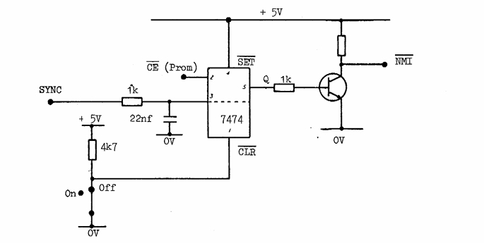
EMMA SST circuit
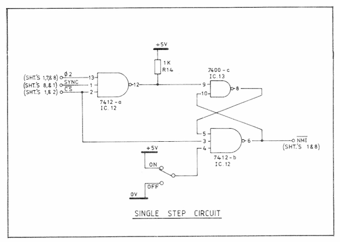
EMMA II SST circuit