post

Load papertape format

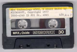
The KIM-1 has two methods of loading programs:
– from audio files on the audio interface
– from papertape from a papertape reader connected to the teletype terminal

(Photos by Dave Wiliams with the MOS KIM-1 Reproduction)

The papertape method is the preferred way available for KIM-1 clone owners, since audio input input hardware is either not present or quite inconvenient and using terminal emulators is already the way we use these computers.

Now papertape format is a special MOS Technology format, already used in the TIM-1. See the KIM-1 user manual for a technical description.
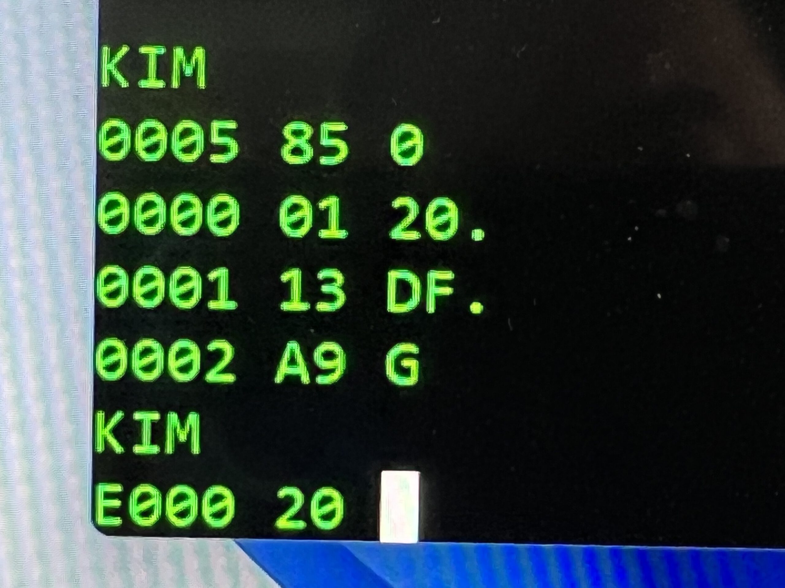
This is for example the papertape output captured with the KIM-1 S command for the memory test program in the Fist Book of KIM

;1800000000A900A885FA8570A2028672A50085FBA601A57049FF850B27
;1800187191FAC8D0FBE6FBE4FBB0F5A672A50085FBA570CA1004A20FF6
;1800300291FAC8D0F6E6FBA501C5FBB0ECA50085FBA672A571CA100F73
;18004804A202A570D1FAD015C8D0F0E6FBA501C5FBB0E8C67210AD0F29
;0B0060A57049FF30A184FA4C4F1C05CE
;0000050005

Load address, data and checksums are in the records.

What the dump above does not show that the KIM-1 inserts in front of every record a series of NULL characters (a character with value 0), to give the papertape device time to do its mechnica work and also helps the slow KIM-1 load routine to do its work after a line end of a record.

A part of a real dump:

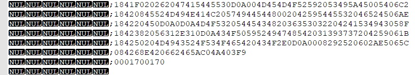
Papertape format is therefore a readable text file, but when captured from a KIM-1 output contains NULL characters.

So if we could send the papertape formatted test file to the KIM, we can load programs.

This requires solutions for the following:

Make a papertape file
The PC utilities section has programs to produce MOS papertape from binaries or other common 8 bit hex formats produced by assembler such as Intel hex, Motorola S-Record
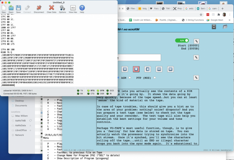
Send a text file
Many terminal emulators that have support for serial allow to capture the serial output to a text file or send a text file to the serial input.
Good examples are nowadays Teraterm for Windows or Minicom for Linux.

Compensate for timing
The KIM-1 character routines are quite primitive and not rebust : bit-banged, not interrupt driven, no hardware ,handshake so no buffering and it is CPU intensive.
When you sent characters quite fast to the KIM-1 (and that means any baud rate from 1200 to 9600, and the KIM-1 also has to do some processing like processsing the record just received, it is to be expected the KIM-1 will be too late reading the next record, skip a record and sync at the next and leave the program received in chaso.
So we need to give time to the poor KIM-1.
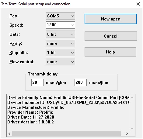
1200 baud, 20 ms character delay, 200 ms line delay is conservative but reliable for me. It is slow ..

An example for Teraterm is shown here:

Decimal mode
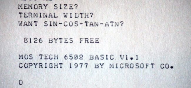
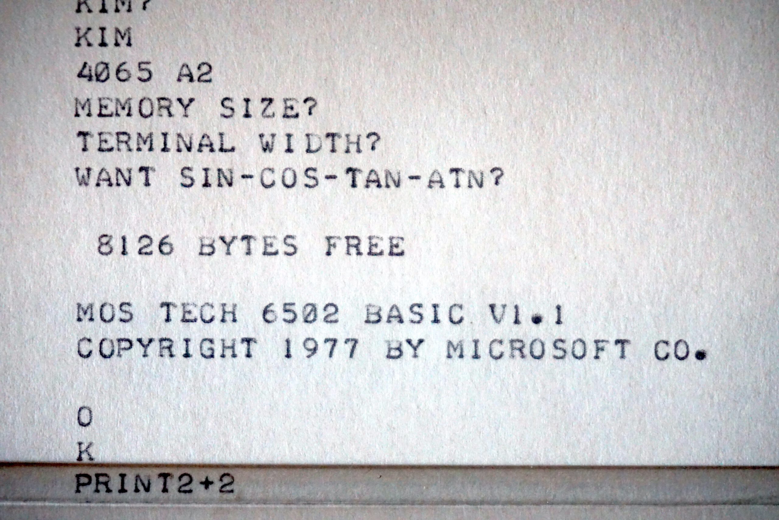
The 6502 NMOS version is in unknown state after reset regarding decimal mode.
Most programs start with the CLD D8 instruction, but not all. Microsoft KIM-1 Basic v1.1 is one of those.

A section from the KIM Hints:

A number of KIM-1 customers have reported difficulty in achieving correct results for the sample problem shown in Sec. 2.4 of the KIM-1 User Manual. In addition, some customers have experienced problems in recording or playback of audio cassettes. (Sec. 2.5 of the KIM-1 User Manual). In all cases, the problems have been traced to a single cause: the inadvertent setting of the DECIMAL MODE.

The 6502 Microprocessor Array used in the KIM-1 system is capable of operating in either binary or decimal arithmetic mode. The programmer must be certain that the mode is selected correctly for the program to be executed. Since the system may be in either mode after initial power-on, a specific action is required to insure the selection of the correct mode. Specifically, the results predicted for the sample problem (Sec. 2.4) are based on the assumption that the system is operating in the binary arithmetic mode. To insure that this is the case, insert the following key sequence prior to the key operations shown at the bottom of Page 11 of the KIM-1 User Manual.

[AD]
[0] [0] [F] [1]
[DA] [0] [0]

This sequence resets the decimal mode flag in the Status Register prior to the execution of the sample program.

The same key sequence may be inserted prior to the key operations shown on pages 14 and 15 for audio cassette recording and playback. These operations will not be performed correctly if the decimal mode is in effect.

In general, whenever a program is to be executed in response to the [GO] key, the programmer should insure that the correct arithmetic mode has been set in the status register (00F1) prior to program execution.

Microsoft Basic 6502

Written in 1976, Microsoft BASIC for the 8 bit MOS 6502 has been available for virtually every 6502-based computer. Also for the SBC’s on this site: KIM-1, SYM-1, AIM 65 and as a port of Applesoft on the Apple 1.

Binary versions and manuals are on the pages dedicated to these machines:

Sources of early Microsoft Basic on 6502 are available on pagetable blog by Michael Steil

Build binaries from source on a Linux system (Raspberry PI OS)

First install CC65 package, the assembler and linker are required.

You need the CC65 package, a C and Macro assembler and linker for the 6502.

https://github.com/cc65/wiki/wiki is broken, https://cc65.github.io/getting-started.html is fine.

git clone https://github.com/cc65/cc65.git
cd cc65
make
sudo make avail

Now get the MS Basic source and assemble the binaries

https://github.com/mist64/msbasic
git clone https://github.com/mist64/msbasic
cd msbasic
./make.sh
cd tmp
ls

and you will see a directory of binaries (.bin), symbol table (.lbl) and object files (.o)

Compare the binary files with the binary files in the msbasic/orig folder and you will see hopefullyy they are identical!

It is not only nice to see the source, now you are able to customize a Microsoft Basic to your likings.

Steps as advised in the pagetable description:
1. Create a .cfg file by copying an existing one.
2. Adapt the make file for the new target.
3. Change the platform specific source files

and assemble again.

For example, the KB9 Basic can be changed:

  • Character in//out to a serial device
  • Control-C handler update
  • Remove the ROR workaround
  • Save/load to another storage device
  • See the KIM Kenner articles for patches on KB9 Basic

An example is this post by Gordon Henderson who made a serial interfaced Commodore Basic by creating a new variant and tweaking some conditionals, replacing the screen editor with the line editing interface of older versions.

KB-9 stands for Microsoft Basic V1.1 for the KIM-1  with 9 digits precision. .
Scanned manual
The original KIM-1 KB9 Microsoft Basic V1.1, audio wave, binary and papertape format

Solid State Tape Device for the (micro)KIM


Willem Aandewiel designed a tape device for the (micro)KIM. With a Wemos D1, ES8266 and ATTiny and some clever software to make the KIM believe a audio cassette recorder is connected.
All details here on Willem’s website.

Willem has now published the next generation, together with a 32K RAM card, of this device.

post

Cassette interface for Micro-KIM

or KIM Clone!

By Timothy Alicie

Demonstrates his  design for a cassette interface for the Micro-KIM single board computer from Briel Computers (a replica of the 1970’s KIM-1 SBC). The original KIM-1 has a built-in cassette interface, but the Micro-KIM replica does not, so I designed and built his own. The design uses a single PIC micro-controller, is very reliable, supports all HyperTAPE speeds, and has the ability to save and play back recorded data into the KIM-1.

post

Home-Brew Cassette Interface for Micro-KIM

Design by Timothy Alicie

Demonstrates his design for a cassette interface for the Micro-KIM single board computer from Briel Computers (a replica of the 1970’s KIM-1 SBC). The original KIM-1 has a built-in cassette interface, but the Micro-KIM replica does not, so I designed and built my own.

The design uses a single PIC micro-controller, is very reliable, supports all HyperTAPE speeds, and has the ability to save and play back recorded data into the KIM-1.


From the source of the microcontroller:

All design files (PCB gerbers, source and hex files PIC microcontroller) in this archive.

/*******************************************************************************
* Micro-KIM Cassette Interface, PIC16F6/27A/28A/48A Implementation
*
* The original KIM-1 uses a PLL and a comparator to implement the receive
* path of the cassette interface. These two parts have been replaced by
* this implementation which runs on a PIC microcontroller.
*
* The KIM-1 cassette format encodes each bit using two tones:
* 1) A high-frequency tone of 3623.188 Hz (1.5X the low-frequency tone)
* 2) A low-frequency tone of 2415.459 Hz
*
* Each bit is broken up into three periods, each of which is 2.484 ms long,
* during which either the low frequency or the high frequency tone is played.
*
* The high frequency tone is always played in the first time period, and the
* low-frequency tone is always played in the last time period. A bit is encoded
* as logic ‘1’ by playing the low-frequency tone in the middle time period, and
* a logic ‘0’ by playing the high-frequency tone in the middle time period:
*
* Logic 1: encoded as HiFreq-LoFreq-LoFreq
* Logic 0: encoded as HiFreq-HiFreq-LoFreq
*
* The KIM-1 cassette interface uses a PLL tuned to distinguish between the
* high and low frequency tone. The output of this PLL is then fed into a
* comparator to generate a logic ‘1’ whenever the high frequency is detected,
* and a logic ‘0’ whenever the low frequency is detected. This logic signal
* is analyzed by the KIM-1 to reconstruct the bit-stream stored on the cassette
* tape. Each bit begins with a low-high transition, and the bit value can be
* determine by the timing of the falling edge generated by the high-frequency
* to low-frequency transition within each bit.
*
* The job of the PIC KIM cassette interface implementation is to perform the
* same function of the original PLL and comparator: analyze the input signal,
* and generate a logic ‘1’ output whenever the high frequency is detected, and
* a logic ‘0’ output whenever the low frequency is detected. The implementation
* is rather simple: analyze the timings of zero-crossings detected in the input
* signal, use this information to determine the frequency of the input signal,
* and generate the output signal based on if the input signal is closer to the
* high frequency, or closer to the low frequency.
*
* The original KIM-1 tape algorithm uses a bit period of 7.452 ms, which is
* three periods of 2.484 ms each. Within each sub-period, exactly 9 cycles of
* the high frequency tone can be played, or exactly 6 cycles of the low
* frequency tone can be played.
*
* Jim Butterfield popularize an alternative called HYPERTAPE, which reduces
* these periods to speed up the data by a factor of 2X, 3X, or 6X. The only
* difference between the HYPERTAPE implementation and the original implementation
* is that the sub-bit periods are reduced. The 2X and 6X sub-bit periods are
* reduced such that a non-integer number of cycles of the high and low frequency
* tones are played within each sub-period. Thus, the PIC detects the frequency
* based on half-cycles to fully-support HYPERTAPE.
*
* Interesting facts:
*
* Original KIM-1 cassette bit-rate: 134.2 bits/sec (402.6 baud, 3 symbols/bit)
* HYPERTAPE 6X bit-rate: 805.2 bits/sec (2415.5 baud, 3 symbols/bit)
*
* Each data byte is represented as two ASCII hex digits, so the effective data
* transfer rate is 8.4 bytes/sec for the original speed, or 50.3 bytes/sec for
* HyperTAPE x6.
*
* High frequency tone: 3623.188 Hz, or 0.276 ms/cycle
* Low frequency tone: 2415.459 Hz, or 0.414 ms/cycle
* Center frequency: 2898.551 Hz, or 0.345 ms/cycle
*
* Frequency detection based on half-wave zero-crossings:
* High frequency tone: zero-crossing every 138 us
* Low frequency tone: zero-crossing every 207 us
*
* Separation between high-frequency and low-frequency zero-crossing: 69 us
* Threshold between high and low-frequency zero crossing: 172.5 us
*
* Implementation Notes:
*
* The bi-color LED lights red when an input signal is present, but it does
* not contain the correct frequencies to be a valid KIM-1 bit stream, for
* example, voice input. The bi-color LED lights green if the input signal
* contains the correct frequencies to be a valid KIM-1 bit stream. While
* receiving data, the green LED should be lit solid to ensure reliable data.

* Comparator 1 (CMP1) is used to detect signal zero-crossings by adding a bias
* to the input AC signal of Vcc/2. The bias is used as the V- comparator input.
*
* RB4 is used to monitor the PB7 line to/from the KIM-1. In audio-output mode,
* (dumping to a tape), the KIM-1 drives this line, so we can use it to detect
* audio-output mode and light the LED when the KIM-1 is dumping data.
*
* Timer 0 (TMR0) is used to light the LED indicators for a certain time period.
*
* Timer 1 (TMR1) is set up to count at 1.0 MHz, and it is used to precisely
* measure the time between zero crossings.
*
* Copyright Timothy Alicie, 2017, Timothy Alicie
*******************************************************************************/

post

G.Eisenack Programmieren von Mikrocomputern CPU 6502 Skriptum

New book added tot the KIM-1 Books resources: (thanks netzherpes)

G.Eisenack Programmieren von Mikrocomputern CPU 6502 Skriptum

PAL-1 extensions

Motherboard 6 slot, 32K RAM , second 6532 board, now on Tindie for the PAL-1 (and Micro-KIM)

post

Adding I/O to the KIM-1

By Bob Applegate

Adding I/O devices that don’t need much address space. On the KIM-1, the space from 1400-17FF is grouped into the K0 block but only 17xx are used, leaving 1400-16FF open for use. To decode that range into four blocks of 256 bytes is easy using a single chip and a few signals from the KIM Clone expansion bus:

Everyone has a 74LS138 in their parts collection, so just connect a few signals from the expansion bus and use one of the three signals from the 138 to decode which block you want to use. Use the A0-A7 address lines to decode into smaller pieces.

PAL-1

A new KIM-1 clone kit in 2021, the PAL-1. In fact, this is a Micro-KIM clone, which is a KIM-1 clone .. Look and specs are like the Micro-KIM, with some improvements like larger keys and a very affordable price. Motherboard, 32K RAM, second 6532 board, RAM board, ROm board, Cassette board, a full KIM-1 and more compatible system.

Designer and seller is software engineer, Liu Ganning, KJXZZ, from Shenzhen, Guangdong, China

The PAL-1 has its own discussion platform at google groups.
For software: see the KIM-1 software page, as the PAL-1 is a KIM-1 with lots of memory!
PAL-1’s difference
First, PAL-1 is a kit, you can assemble it, test it and run it all by yourself —— an unique experience!
The PAL-1 addressing mode is completely implemented in accordance with the design of KIM-1, so it is compatible with most programs developed on KIM-1.
PAL-1 has 2K bytes ROM (complete KIM-1 Monitor), 5K bytes RAM, one 6532 RIOT chip on board, provides two 8-bit bidirectional I/Os, these I/Os are mainly used to support 23-key keyboard input and drive 6 seven-segment LED displays. In addition, PAL-1 also provides RS232 serial port to support terminal operation and 40-pin expansion port for future upgrade. The TTY/RS232 interface and expansion interface pinout uses the design of Rich Dreher and Vince Briel (MicroKIM compatible).
Besides the PAL-1 also a 6 slot motherboard, a 32K RAM board and a RIOT board (the second 6532 making it a complete KIM-1) and a cassette interface baord are available. A ROM boards adds many programs like programming languages Basic, Forth etc.

The main differences between PAL-1 and KIM-1 are illustrated by the following two figures in the “KIM-1 User Manual”.
PAL-1 absence half I/O and Timer (red) Picture 11 (see the RIOT board how to add this!)

PAL-1 onboard RAM increased to 5K (all green spaces are available) Picture 10

What is included
The PAL-1 Kit includes mainboard PCB, ICs, pre-programmed ROM, passive components, sockets & headers.
Print version BOM, Pinout, Schematic.

/tbody>

User Manual PAL-1
Schematic PAL-1
Bill of Materials
Motherboard
32K RAM expansion manual
32k RAM board schematic
RIOT expansion manual
RIOT board schematic
ROM expansion manual 1.0
ROM expansion manual_v1.2 (28C256)
Operation guide PAL-1 EPROM Expansion Card
ROM board 1.0 schematic
ROM board schematic V1.2
ROM PAL-1 ROM image
Cassette expansion manual
Cassette board schematic
Cassette board BOM

Modification for TTL USB interface

The two following images show how to adapt the PAL-1 to a TTL USB interface instead of RS232. also supplying power from USB.

Modification of ROM board 1.0 for 28C256 EEPROM

The ROM card v1.0 is designed for using 27C256 and 27C512 EPROM, but these UV-erase chip will need much patient when you’re doing a lot of ROM program. So the PAL-1 got a new version ROM card, v1.2, to support the more convenience EEPROM, the 28C256.

Even the v1.0 ROM card designed for the 27Cxxx, you can also use the 28C256 on it. Just one soldering work need to do, populate the high 32K switch using a switch (like K3-2235D-F1) or 3-pin 2.54mm pin header (solder at the inner side of the high 32K switch).

When you need to using a 28C256, you can set and keep the low 32K switch to HIGH, then using the high 32K switch/jumper to select the low 16K bank or the high 16K bank of 28C256 just like normal.


A second RAM board can be modified to add 16K extra.
Modify a 32K RAM card for the upper RAM area. Just need to cut 1 wire and solder 2 jumper wires like below:


The KIM ROM needs the highest area of 64K for the vectors, so the Exxx to FFFF cannot be decoded with the second 32K RAM card.
We can use $A000~$DFFF (16K) more RAM with the second RAM card installed.

Some pictures of the two RAM card system running.

RAM test:


KIM Clone software

KIM Clone software

Look at the KIM-1 software page for a wide offer of KIM-1 software, suitable also for the KIM Clone.

KIM Monitor

The Corsham variant of the KIM Monitor is for the most part made up of the code in the 6530-002 ROM. The 6530-003 (audio cassette save/load) ROM was removed.
Placed in the main ROM of the KIM Clone.

List of changes to the original KIM-1 ROMs:

  1. Removal of the (6530-003) code to save/load from cassette tape.
  2. Lunar Lander (First Book of KIM) added.
  3. Farmer Brown (First Book of KIM) added.
  4. New X command from TTY to enter the Corsham Technologies xKIM extended monitor.
  5. L command also loads Intel hex file (from input, send file in terminal emulator, like you can do with papertape files)

There is no technical reason why you could not load the original KIM 6530-002 and 6530-003 ROMs into the KIM Monitor EPROM. The Corsham KIM Monitor is a bit more convenient.

Source of Corsham KIM Monitor

xKIM Monitor
Placed in the extra EEPROM

Extra commands in teletype mode.

  ? ........... Show this help
  D ........... Disk directory
  E xxxx ...... Edit memory
  H xxxx xxxx . Hex dump memory
  J xxxx ...... Jump to address
  K ........... Go to KIM monitor
  L ........... Load HEX file
  M xxxx xxxx . Memory test
  P ........... Ping disk controller
  T ........... Type disk file
  ! ........... Do a cold start

Source of Corsham KIM Monitor
a>

Corsham eXtended KIM Monitor Manual
Source of Corsham KIM Monitor

Microsoft 8K BASIC
Download the original KB9 binary, dumped from official Micro-soft (no typing error, original name!) cassette audio tape, and documentation from this site.

Or build your own version from the pagetable blog (for which my KB9 was the KIM-1 version as input!) Install the CC65 package, then run the make.sh command, then look at the file tmp/kb9.bin, You’ll need to convert that raw binary image to a file suitable for downloading to the KIM, see the KIM-1 tools for a utility. All of these needs at least 12K of RAM starting at $2000 in the KIM-1

Binaries of KB9

Here is a file suitable for downloading onto a KIM-1. It loads at $2000 but to run it you’ll need to start at $4065. Use the L command in KIM-1’s monitor, then upload the file. I strongly suggest that you change your terminal emulator so it adds a 200 ms pause at the end of each line. Once it loads, run it by going to 4065 and running it.
4065 G
To see the easter egg, answer “A” when it asks for memory size.

Original KIM-1 Microsoft BASIC KB9

This is still experimental but I have a version which uses functions in the xKIM monitor (present on the KIM Clone or on the 60K RAM/EPROM board) to save/load from the SD Card System. It also has a DIR command. This is an Intel HEX file and must be loaded from the xKIM “L” command:

Download hex file xkim

This loads and runs at $2000.

Tom Pittman’s Tiny BASIC
Tom distributed a very small BASIC that needed about 3K to run, and was available on paper tape for $5!!! He has quite a bit about it at:
http://www.ittybittycomputers.com/IttyBitty/TinyBasic/

Here is the source code, listing, and binary to my disassembly which includes a lot of comments and notes from Tom Pittman:
Tiny Basic source
Tiny Basic listing

A ready-to-run binary which loads at $0200 and should have RAM up to $13FFL
Tiny Basic hex file

Bob’s Tiny BASIC
by Bob Applegate

All the early issues of Dr Dobb’s Journal discussed using using an intermediate language (IL) to write a general interpreter, then writing a BASIC interpreter using the IL language. Nobody used this except for Tom Pittman. I liked the idea and about five years ago wrote my own BASIC using that approach. It is buggy, but the sources are on the Corshams github so anyone can take them, hopefully debug things, and put fixes back in place. My version also has commands to save/load programs to/from a Corsham Technologies’ SD Card System.

Source and documentation of Bob’s Tiny Basic

And a binary version that can be run starting at address 0200

AS65 assembler

The software above was assembled with the AS65 Kingwoods assembler, a command line utility for Windows (including 10).

Download here AS65

A typical build for a bianry and hex output would be:

REM Build xKIM
as65 -l -s2 xKIM.asm
as65 -l xKIM.asm

Type “as65 ?” for help

Memory Test

by Bob Applegate
This memory test was originally based on Jim Butterfield’s memory test program in the First Book of Kim, but has grown a bit. This now tests every memory location using a rolling 9-bit pattern. Ie the pattern repeats every 9 bytes, so this will detect most shorted address line problems. I use this to test memory boards, so it will run forever unless an error is detected. At the end of each pass, a ‘.’ is printed.

This does output to the TTY port, so if you’re only using the default KIM display, the output functions will need to be tweaked. Not hard to do, but I didn’t need it.

Written February 2006 by Bob Applegate, but it uses some bits of code from Jim Butterfield, and Ross Archer
Memory test soource and hex file

Microchess Peter Jennings
Adapted for KIM clone by tennyson.neil

Source and hex file Microchess for the KIM clone