
Design by Timothy Alicie
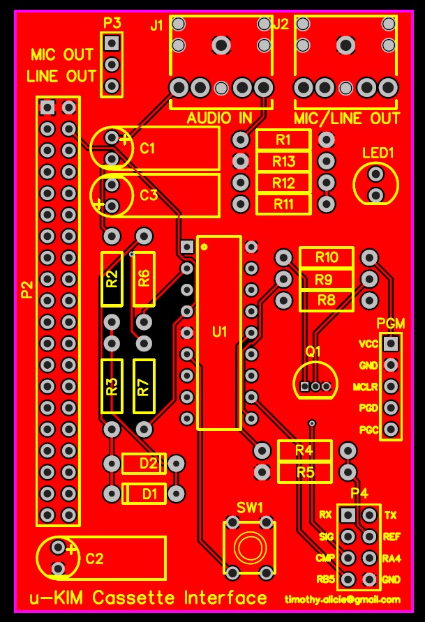
Demonstrates his design for a cassette interface for the Micro-KIM single board computer from Briel Computers (a replica of the 1970’s KIM-1 SBC). The original KIM-1 has a built-in cassette interface, but the Micro-KIM replica does not, so I designed and built my own.
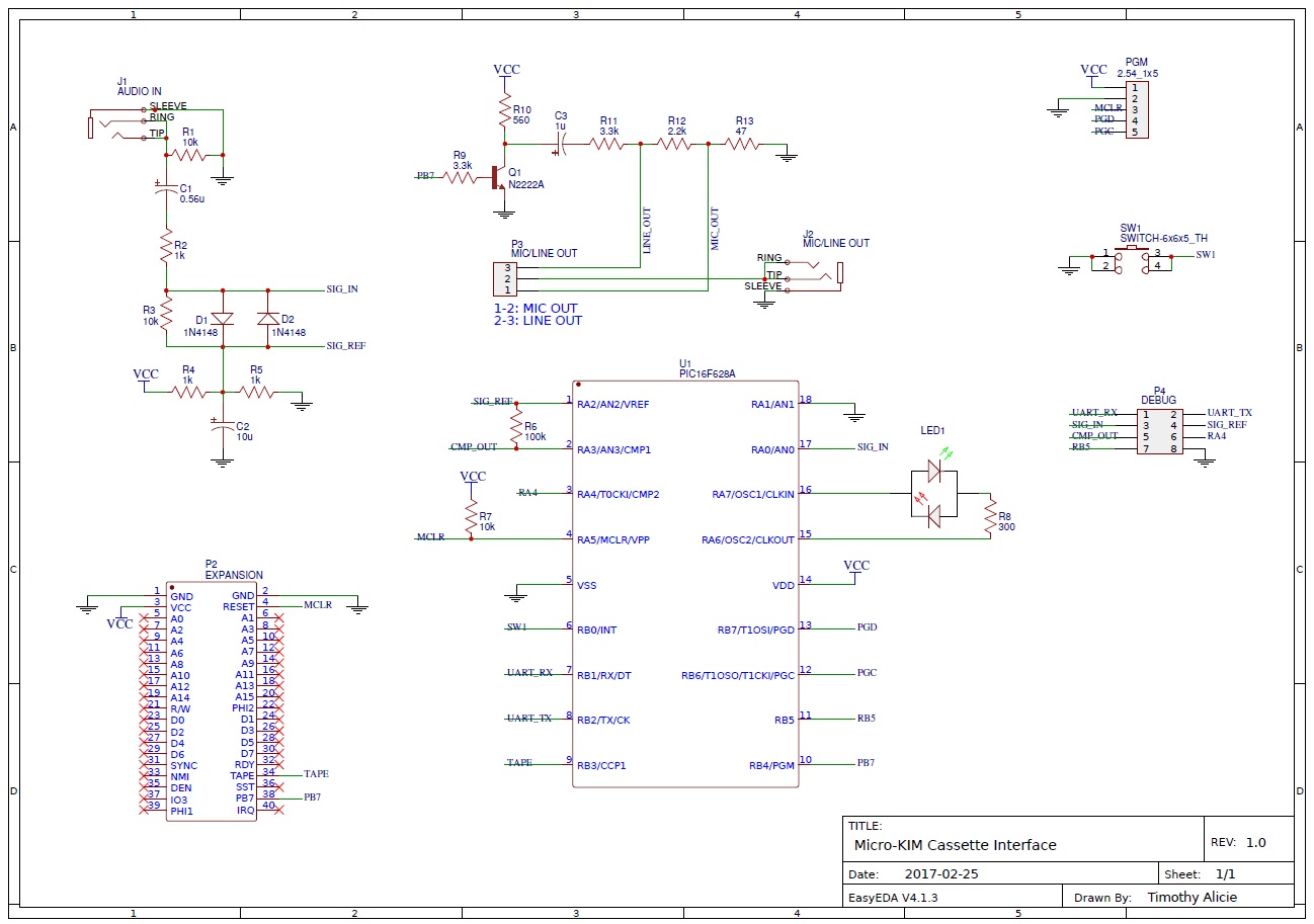
The design uses a single PIC micro-controller, is very reliable, supports all HyperTAPE speeds, and has the ability to save and play back recorded data into the KIM-1.
From the source of the microcontroller:
All design files (PCB gerbers, source and hex files PIC microcontroller) in this archive.
/*******************************************************************************
* Micro-KIM Cassette Interface, PIC16F6/27A/28A/48A Implementation
*
* The original KIM-1 uses a PLL and a comparator to implement the receive
* path of the cassette interface. These two parts have been replaced by
* this implementation which runs on a PIC microcontroller.
*
* The KIM-1 cassette format encodes each bit using two tones:
* 1) A high-frequency tone of 3623.188 Hz (1.5X the low-frequency tone)
* 2) A low-frequency tone of 2415.459 Hz
*
* Each bit is broken up into three periods, each of which is 2.484 ms long,
* during which either the low frequency or the high frequency tone is played.
*
* The high frequency tone is always played in the first time period, and the
* low-frequency tone is always played in the last time period. A bit is encoded
* as logic ‘1’ by playing the low-frequency tone in the middle time period, and
* a logic ‘0’ by playing the high-frequency tone in the middle time period:
*
* Logic 1: encoded as HiFreq-LoFreq-LoFreq
* Logic 0: encoded as HiFreq-HiFreq-LoFreq
*
* The KIM-1 cassette interface uses a PLL tuned to distinguish between the
* high and low frequency tone. The output of this PLL is then fed into a
* comparator to generate a logic ‘1’ whenever the high frequency is detected,
* and a logic ‘0’ whenever the low frequency is detected. This logic signal
* is analyzed by the KIM-1 to reconstruct the bit-stream stored on the cassette
* tape. Each bit begins with a low-high transition, and the bit value can be
* determine by the timing of the falling edge generated by the high-frequency
* to low-frequency transition within each bit.
*
* The job of the PIC KIM cassette interface implementation is to perform the
* same function of the original PLL and comparator: analyze the input signal,
* and generate a logic ‘1’ output whenever the high frequency is detected, and
* a logic ‘0’ output whenever the low frequency is detected. The implementation
* is rather simple: analyze the timings of zero-crossings detected in the input
* signal, use this information to determine the frequency of the input signal,
* and generate the output signal based on if the input signal is closer to the
* high frequency, or closer to the low frequency.
*
* The original KIM-1 tape algorithm uses a bit period of 7.452 ms, which is
* three periods of 2.484 ms each. Within each sub-period, exactly 9 cycles of
* the high frequency tone can be played, or exactly 6 cycles of the low
* frequency tone can be played.
*
* Jim Butterfield popularize an alternative called HYPERTAPE, which reduces
* these periods to speed up the data by a factor of 2X, 3X, or 6X. The only
* difference between the HYPERTAPE implementation and the original implementation
* is that the sub-bit periods are reduced. The 2X and 6X sub-bit periods are
* reduced such that a non-integer number of cycles of the high and low frequency
* tones are played within each sub-period. Thus, the PIC detects the frequency
* based on half-cycles to fully-support HYPERTAPE.
*
* Interesting facts:
*
* Original KIM-1 cassette bit-rate: 134.2 bits/sec (402.6 baud, 3 symbols/bit)
* HYPERTAPE 6X bit-rate: 805.2 bits/sec (2415.5 baud, 3 symbols/bit)
*
* Each data byte is represented as two ASCII hex digits, so the effective data
* transfer rate is 8.4 bytes/sec for the original speed, or 50.3 bytes/sec for
* HyperTAPE x6.
*
* High frequency tone: 3623.188 Hz, or 0.276 ms/cycle
* Low frequency tone: 2415.459 Hz, or 0.414 ms/cycle
* Center frequency: 2898.551 Hz, or 0.345 ms/cycle
*
* Frequency detection based on half-wave zero-crossings:
* High frequency tone: zero-crossing every 138 us
* Low frequency tone: zero-crossing every 207 us
*
* Separation between high-frequency and low-frequency zero-crossing: 69 us
* Threshold between high and low-frequency zero crossing: 172.5 us
*
* Implementation Notes:
*
* The bi-color LED lights red when an input signal is present, but it does
* not contain the correct frequencies to be a valid KIM-1 bit stream, for
* example, voice input. The bi-color LED lights green if the input signal
* contains the correct frequencies to be a valid KIM-1 bit stream. While
* receiving data, the green LED should be lit solid to ensure reliable data.
* Comparator 1 (CMP1) is used to detect signal zero-crossings by adding a bias
* to the input AC signal of Vcc/2. The bias is used as the V- comparator input.
*
* RB4 is used to monitor the PB7 line to/from the KIM-1. In audio-output mode,
* (dumping to a tape), the KIM-1 drives this line, so we can use it to detect
* audio-output mode and light the LED when the KIM-1 is dumping data.
*
* Timer 0 (TMR0) is used to light the LED indicators for a certain time period.
*
* Timer 1 (TMR1) is set up to count at 1.0 MHz, and it is used to precisely
* measure the time between zero crossings.
*
* Copyright Timothy Alicie, 2017, Timothy Alicie
*******************************************************************************/