On this page software for the TIM is described.
– DEMON
– Tiny Basic ad Resident Assembler Program
– Focal-65 V3D
– adaptations to Jolt sofware by Scott LaLombard
– Jolt/Superjolt/TOM simulator
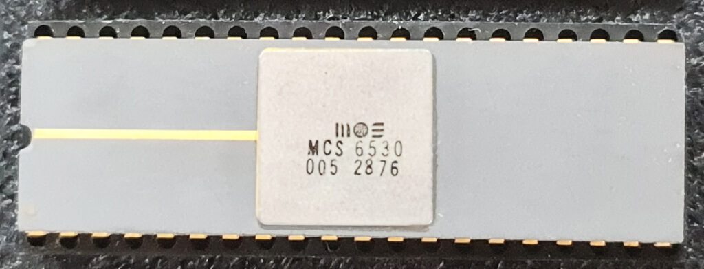
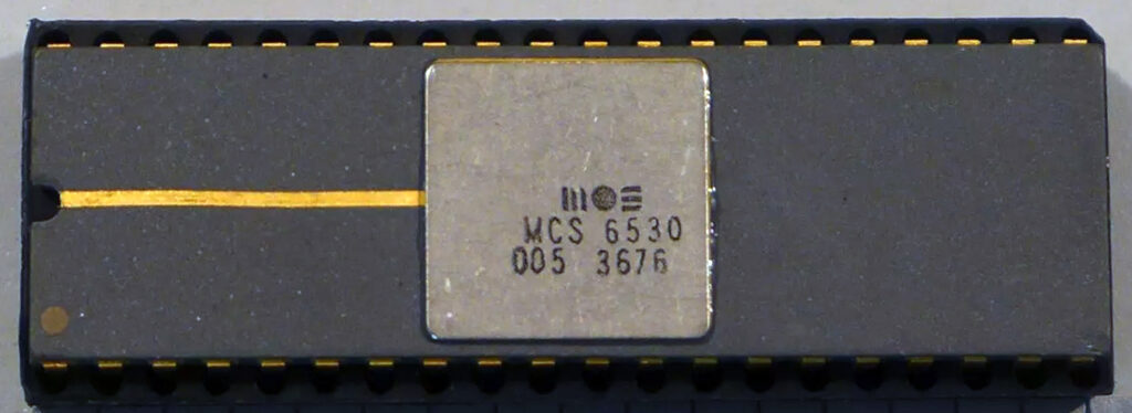
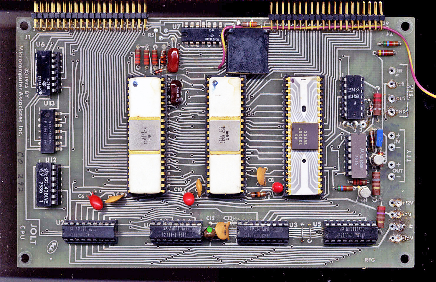
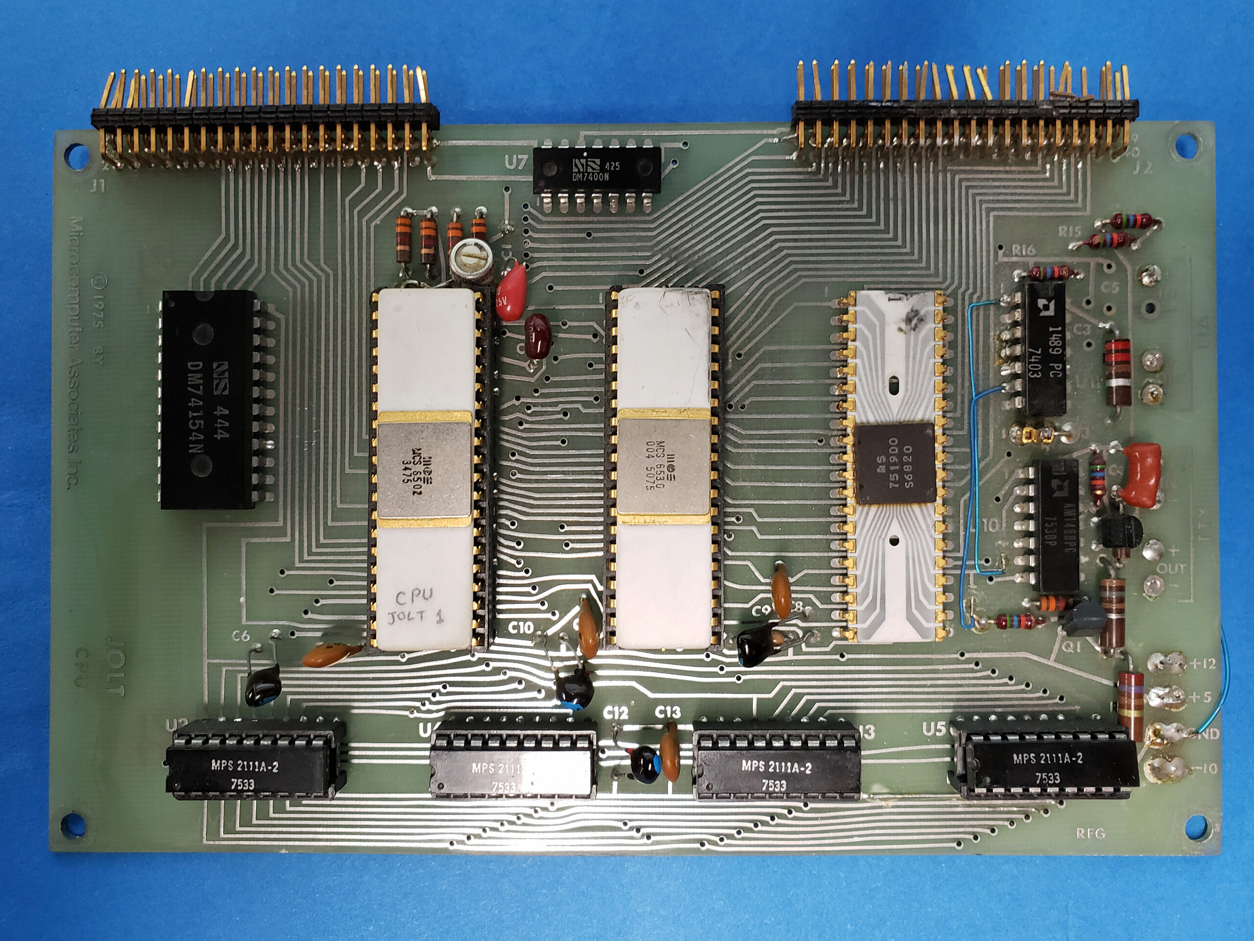
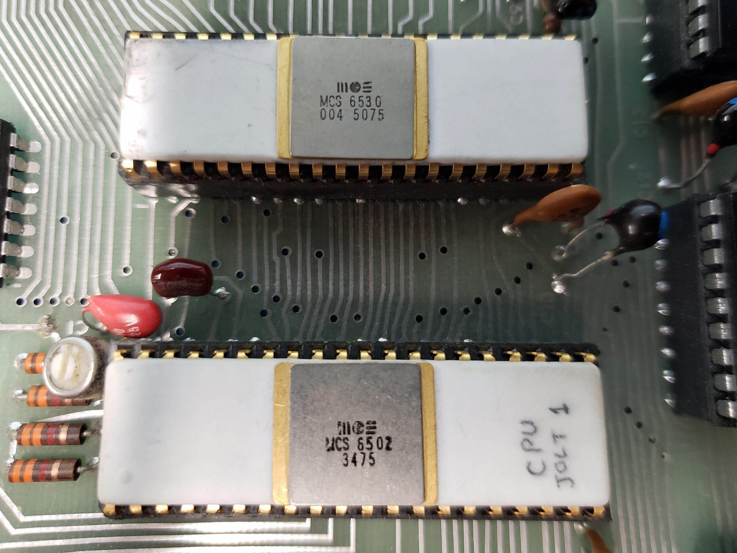
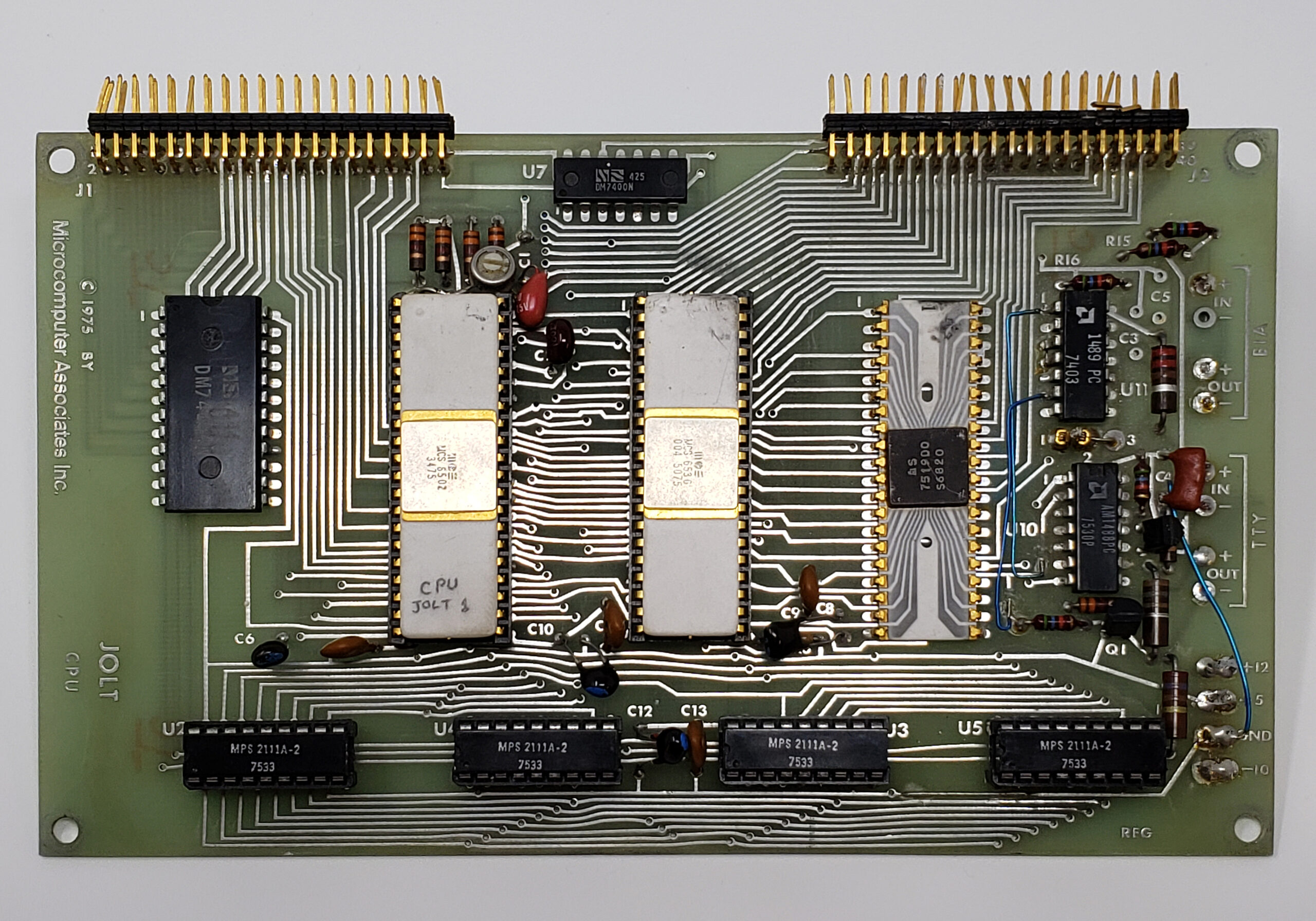
DEbug MONitor (the program in the TIM 6530-004)
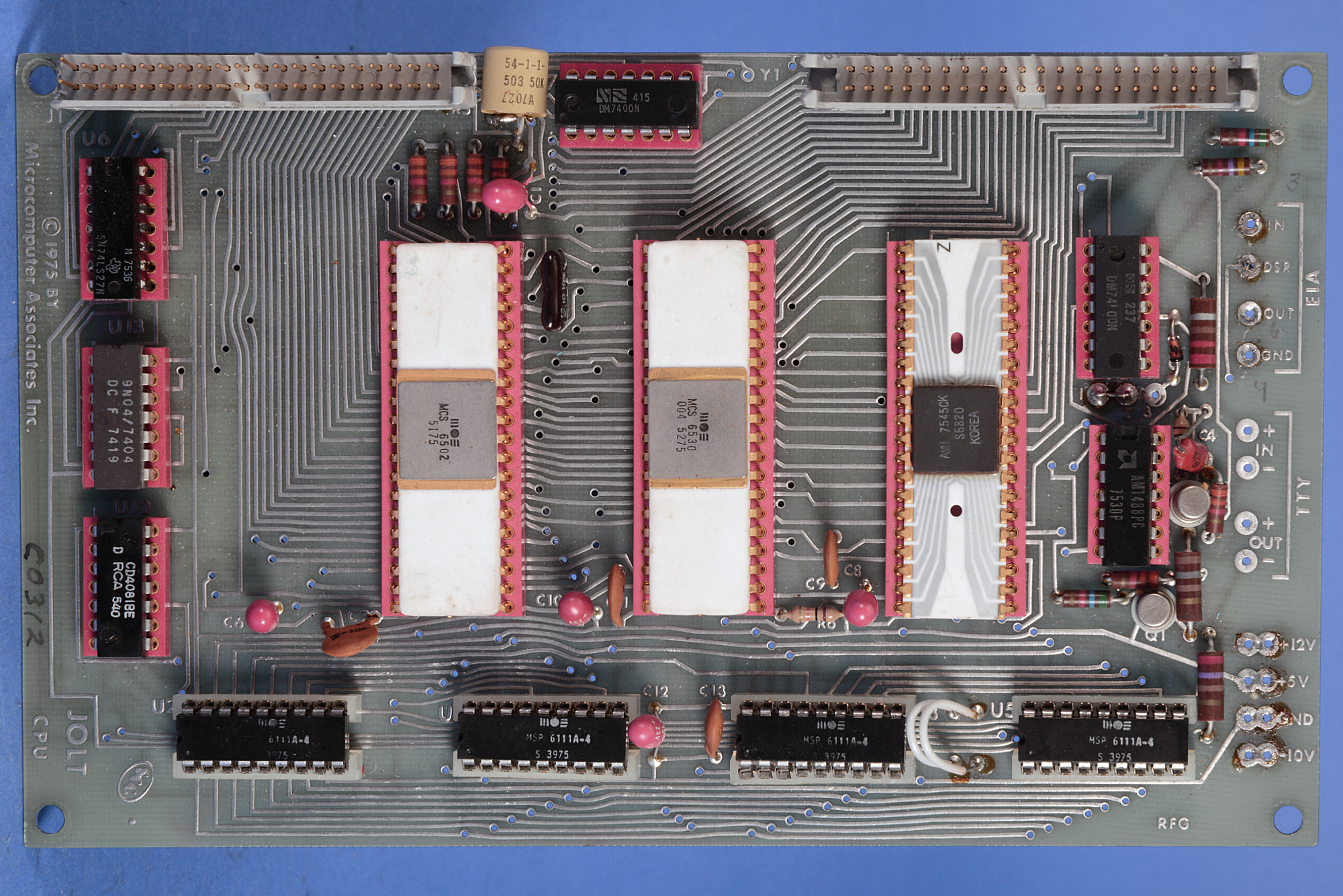
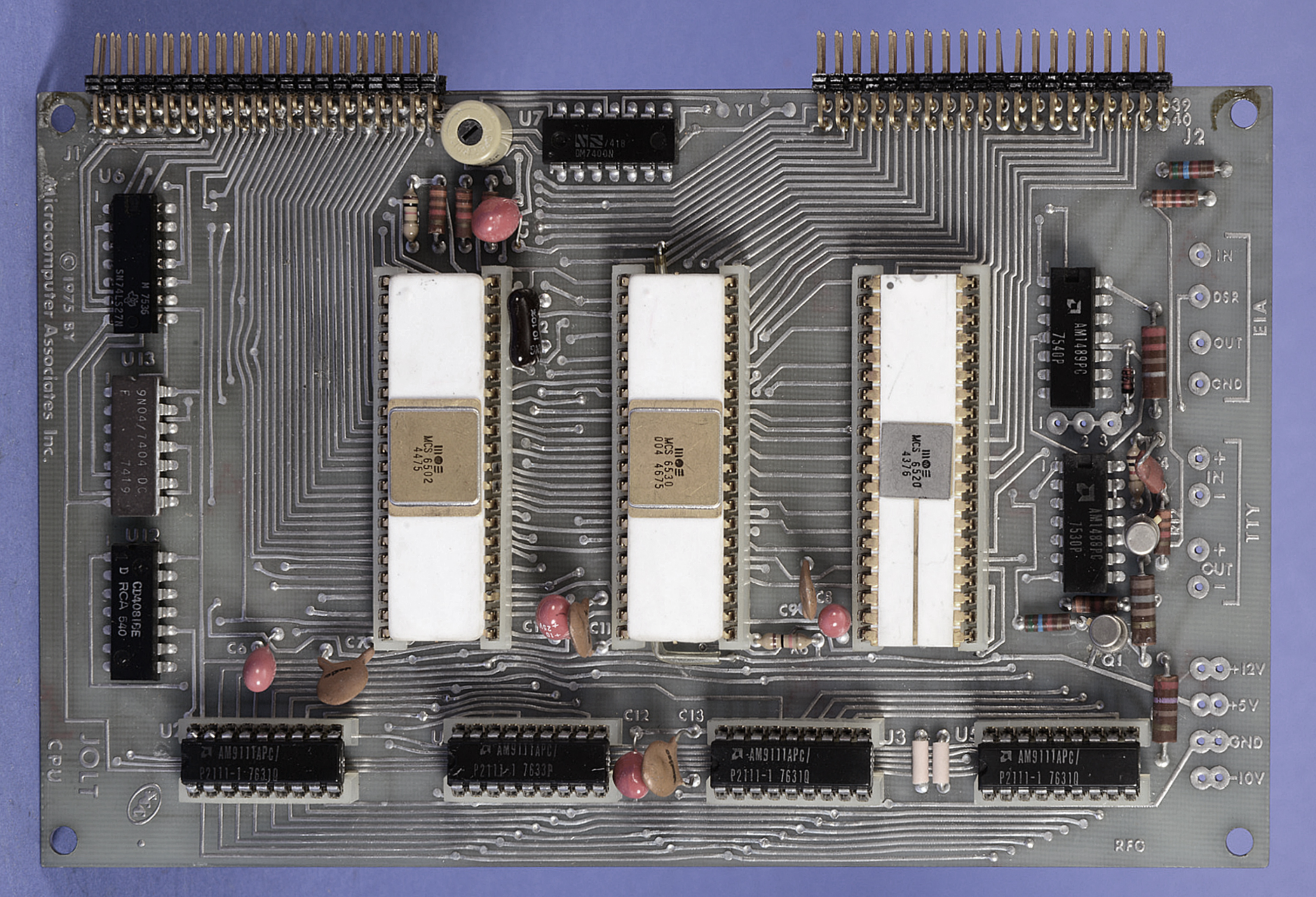
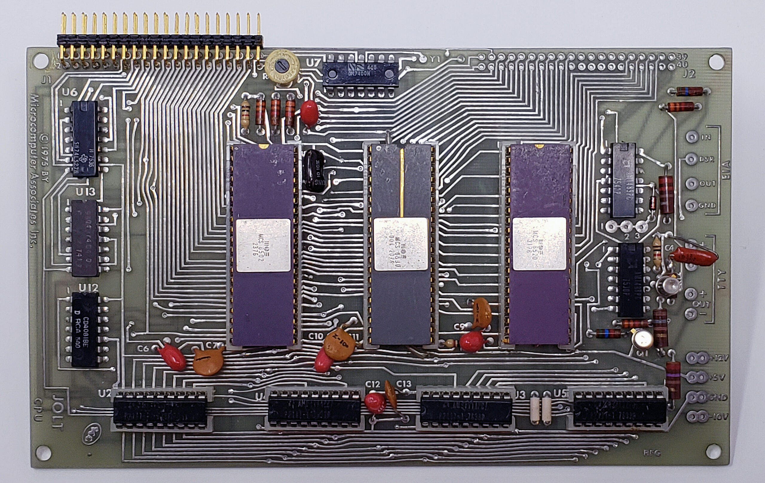
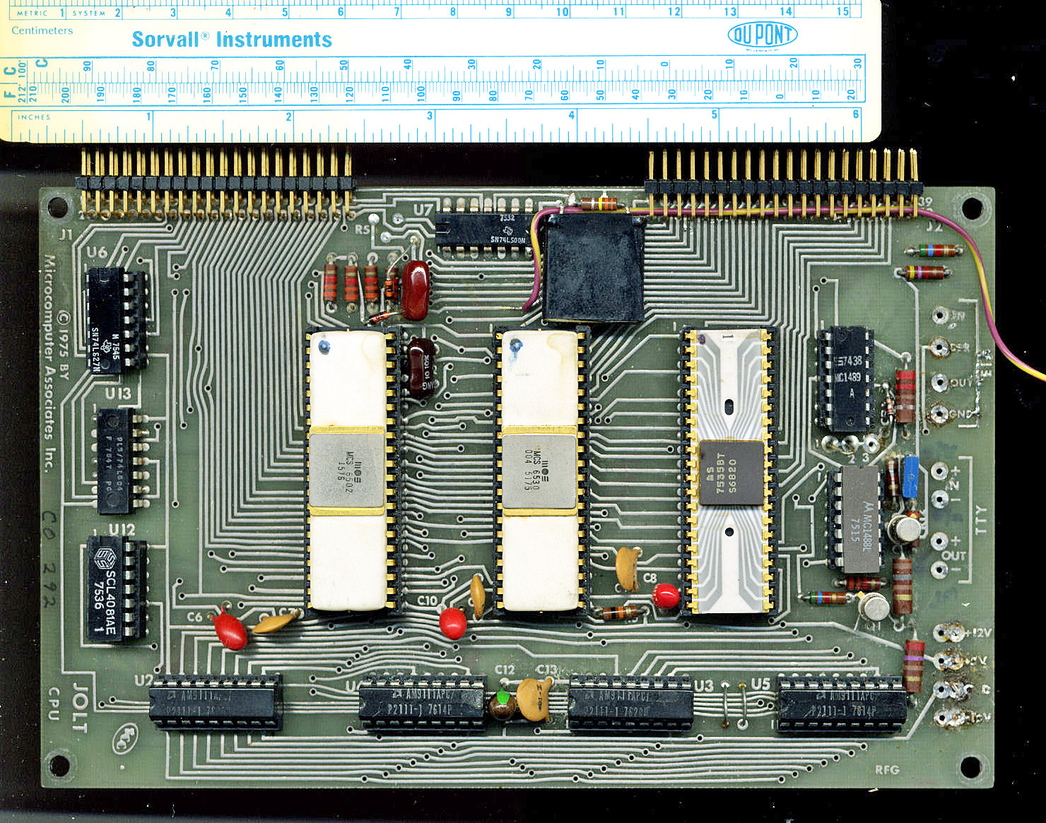
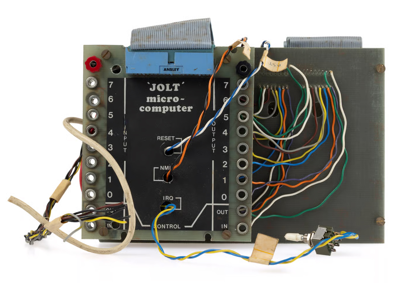
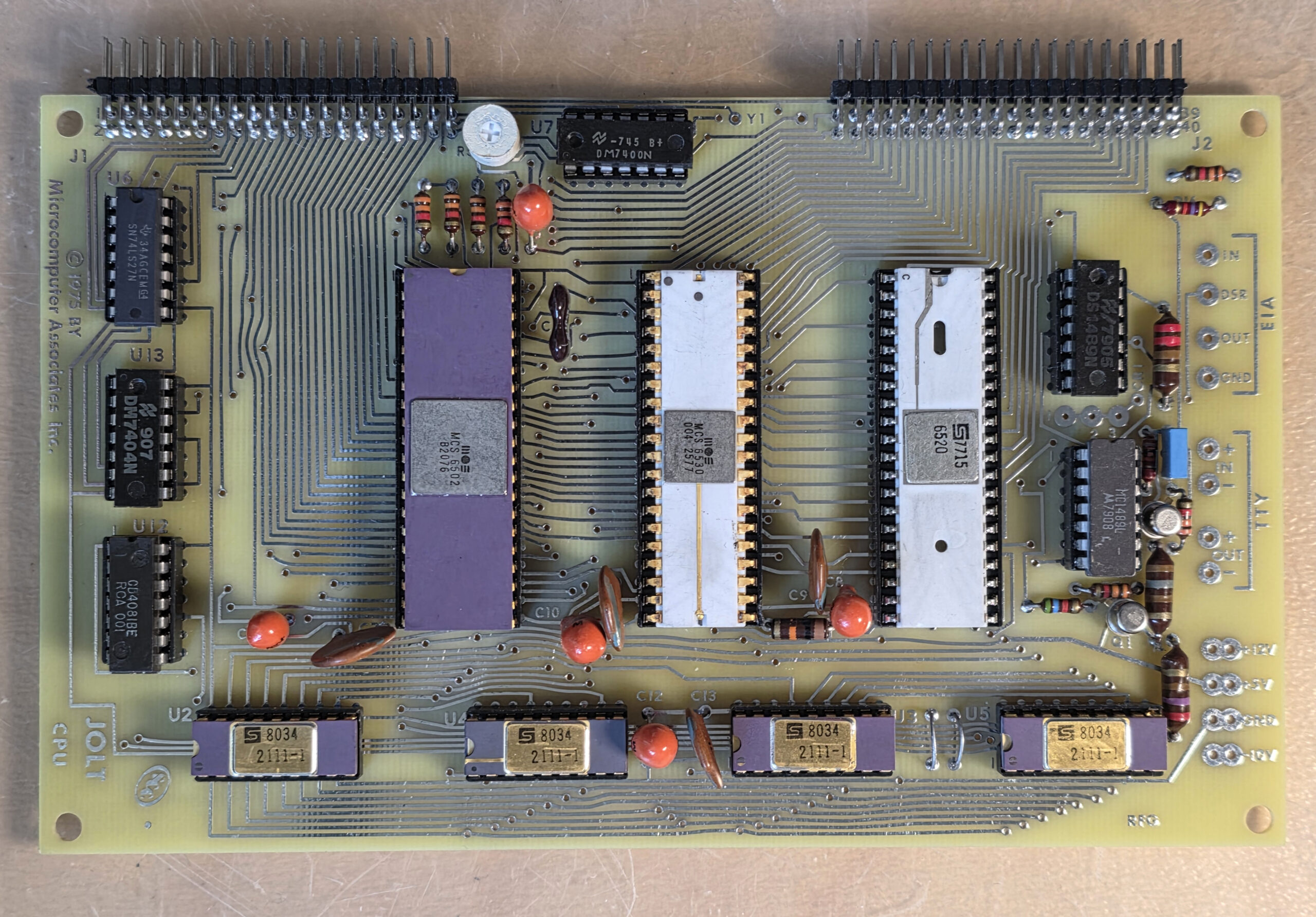
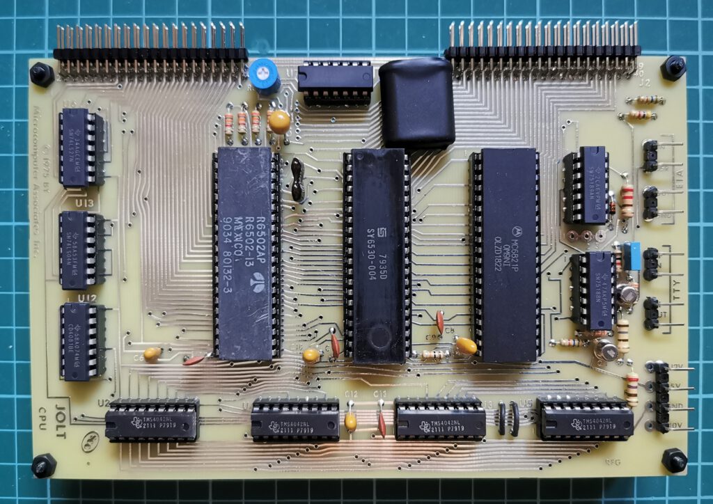
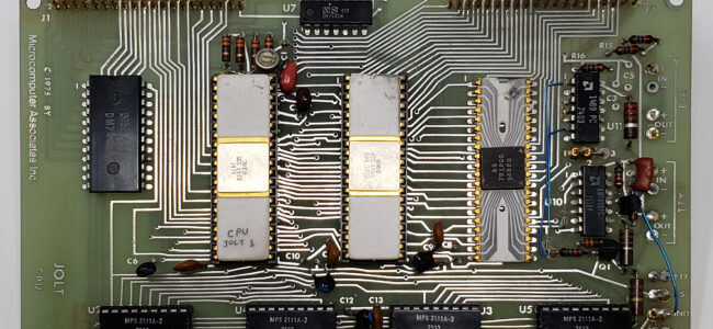
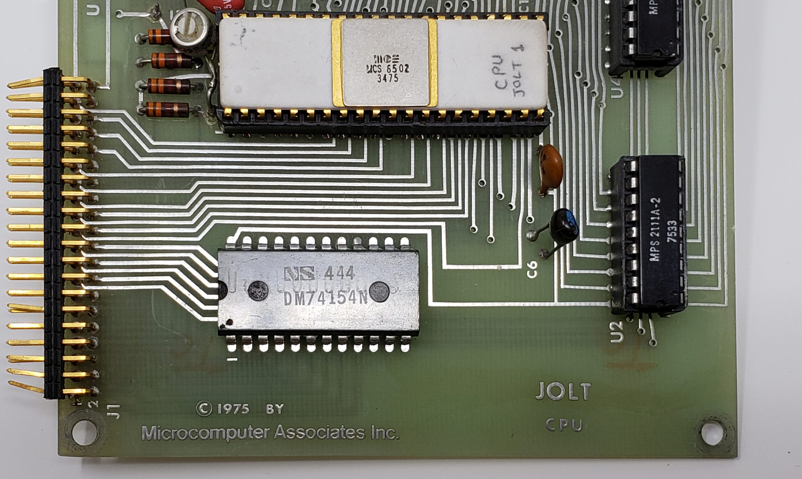
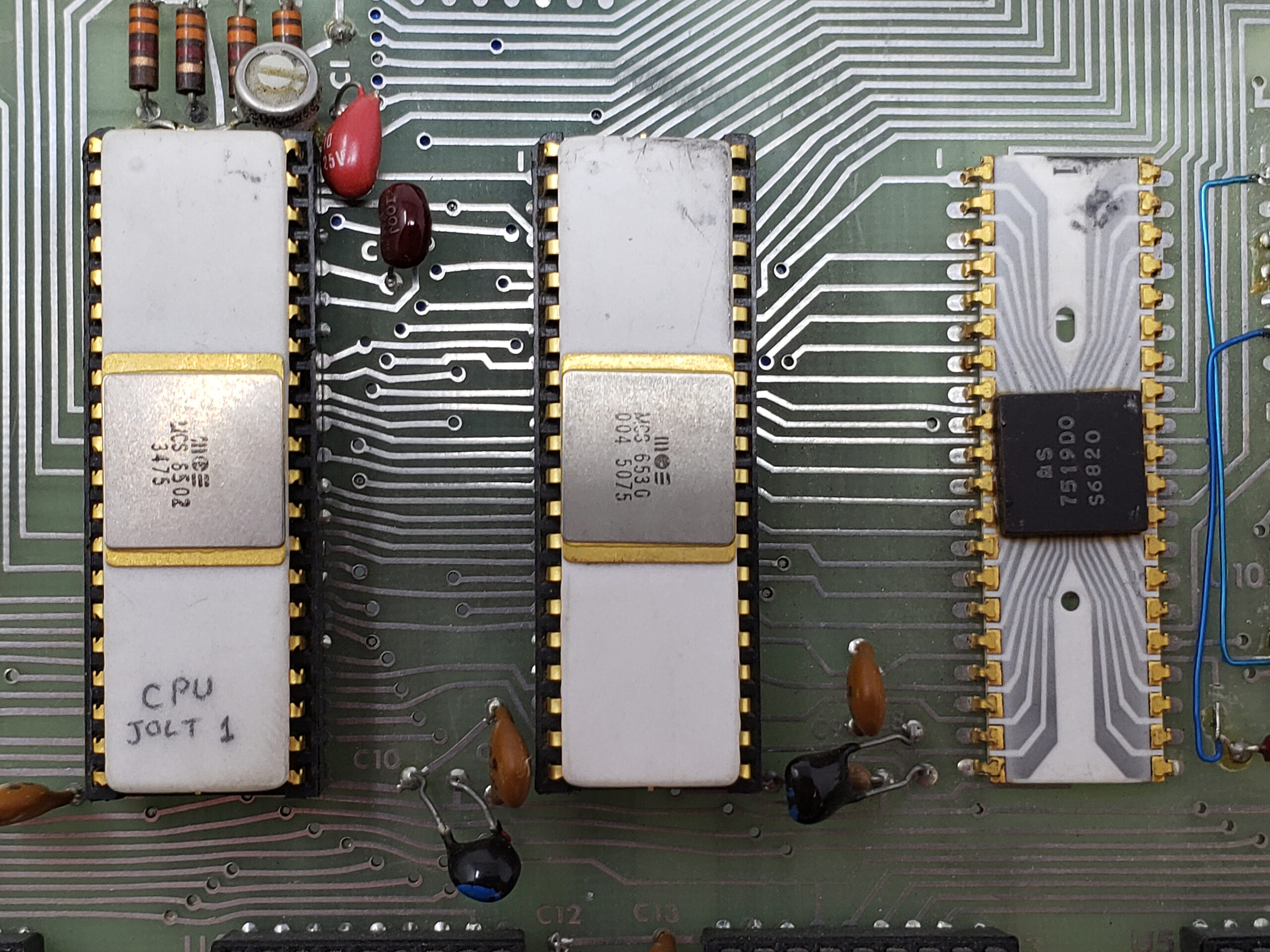
The JOLT CPU card comes complete with DEMON, MAl’s debug monitor program. The program is located in the 1,024 byte, Read Only Memory (ROM) of the multi-function 6530 chip and is therefore
completely protected against any alteration. DEMON provides a permanently available general purpose monitor program to aid users in developing hardware and software for MAl’s JOLT series of microcomputers.
DEMON’s Features Include:
• Self adapting to any terminal speed from 10-30 cps,
• Display and Alter CPU registers,
• Display and Alter Memory locations,
• Read and Write/Punch hexadecimal formatted data,
• Write/Punch BNPF format data for PROM programmers,
• Unlimited breakpoint capability,
• Separate non-maskable interrupt entry and identification,
• External device interrupts directable to any user location or defaulted to DEMON recognition,
• Capability to begin or resume execution at any location in memory,
• Completely protected, resident in Read Only Memory,
• Capability to bypass DEMON entirely to permit full user program
control over system,
• High speed 8-bit parallel input option, and
• User callable I/O subroutines.
DEMON’s Command Set Includes:
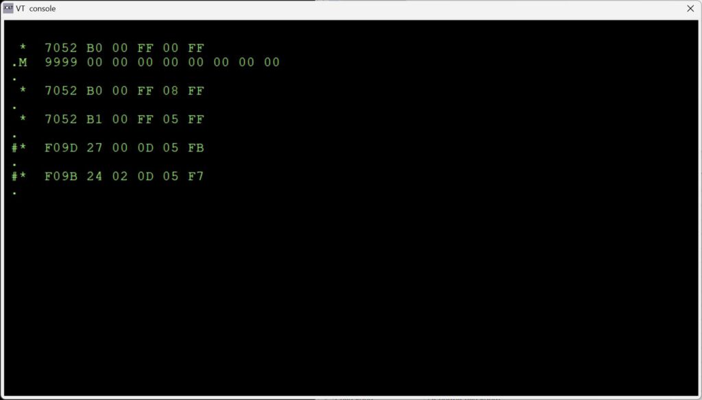
.R Display registers (PC,F,A,X,Y,SP)
.M ADDR Display memory (8 bytes beginning at ADDR)
: DATA Alters previously displayed item
.LH Load hexadecimal tape
.WB ADDR1 ADDR2 Write BNPF tape (from ADDR1 to ADDR2)
.WH ADDR1 ADDR2 Write hexidecimal tape (from ADDR1 to ADDR2)
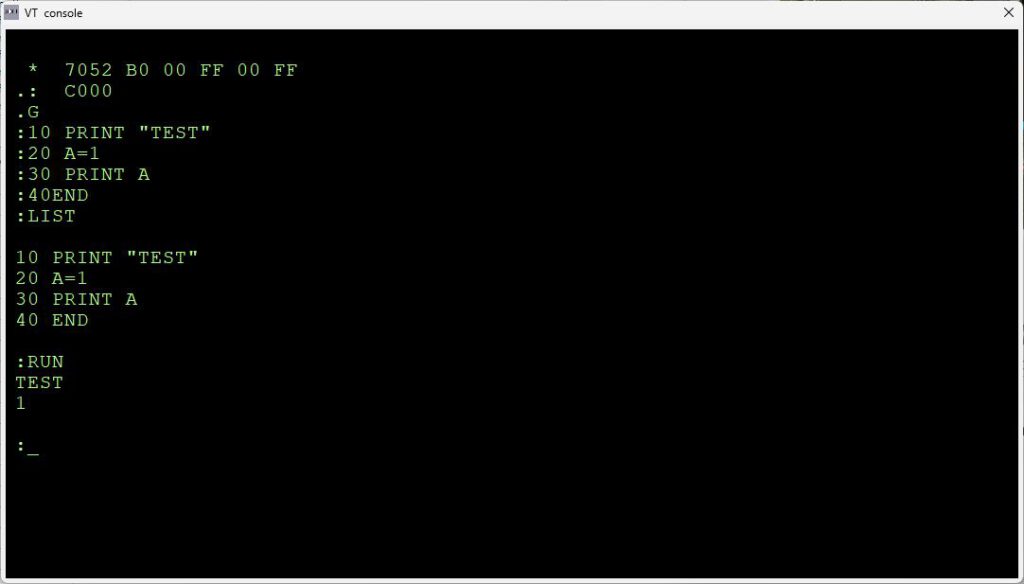
.G Go, continue execution from current PC address
.H Toggles high-speed-reader option (if it is on, turns it off; if off, turns on)
See the TIM manual for more information on DEMON, the name MAI uses for the TIM program.
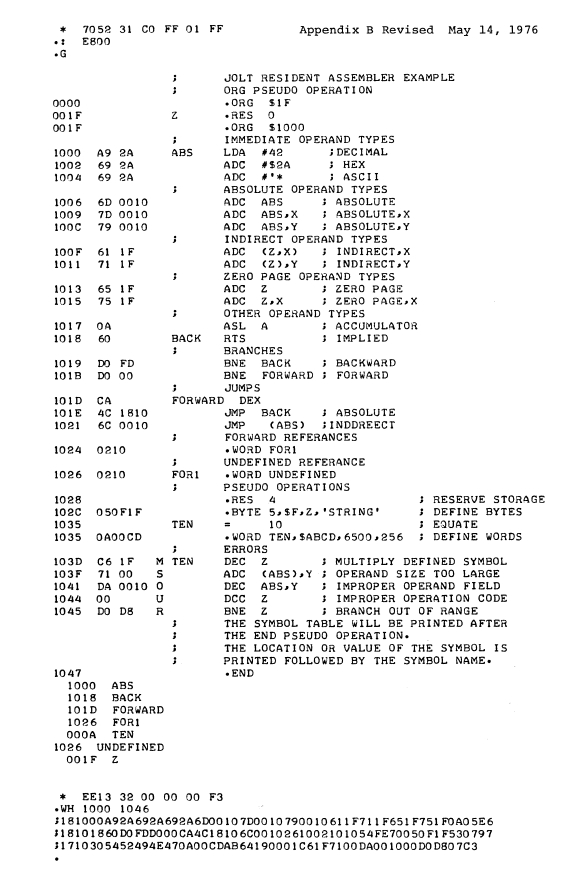
RAP — 1.75K Byte Resident Assembler Program
(This looks like a predecessor of the RAE of the SYM-1). The JOLT Resident Assembler Program (RAP) is designed for use on JOLT systems equipped with at least 4K bytes of RAM memory. RAP has some significant advantages over conventional assemblers:
1. Resident as part of the JOLT system on PROM chips. The assembler never has to be read into volatile memory before use. It, just like the DEMON monitor, is instantly available. In addition, costly time sharing services are not needed for cross assemblies.
2. Operates on one pass of the source code. The source tape is read in only once, thereby increasing assembler speed by a factor of two over conventional assemblers that make two or three passes over the source code.
3. Small in size. The assembler is smaller by a factor of 4 or 5 over comparable assemblers. Its size guarantees the smallest number of PROM chips needed and minimizes printed circuit board space requirements. With the assembler PROM chips installed in your JOLT PROM board (at address E800 hex), the assembler may be activated by reading the source code input on the console input device and transfering to location E800 hex using the DEMON monitor. As source code is being read in, a listing is produced on the console printer and the object code is generated directly into RAM at the addresses specified by the origin directive (.ORG).
After the assembly is complete, the object code may be punched onto paper tape or executed directly using DEMON. The assembler assumes RAM at locations 1FFF hex and lower to be available for symbol table usage. RAP uses an efficient symbol table algorithm and users can normally expect that about 4 to 6 bytes of RAM will be used for each symbol or that a 3000 byte program would use approximately 800 bytes for the entire symbol table (locations 1CEO to 1FFF hex). This space need not be left unused if buffers,’ etc. are allocated to it. The Resident Assembler Program is compatible with the MAS Technology Cross Assembler with the following exceptions:
1. Expressions and * (used for current program counter) are not allowed.
2. Thee .OPT and .PAGE pseudo operations are not implemented.
3. Octal and binary numbers are not implemented.
4. .ORG is used instead of *= to origin program.
5. .RES is used for reserving storage.
FOCAL
See the FOCAL065 V3D page for a TIM version of the FOCAl language.
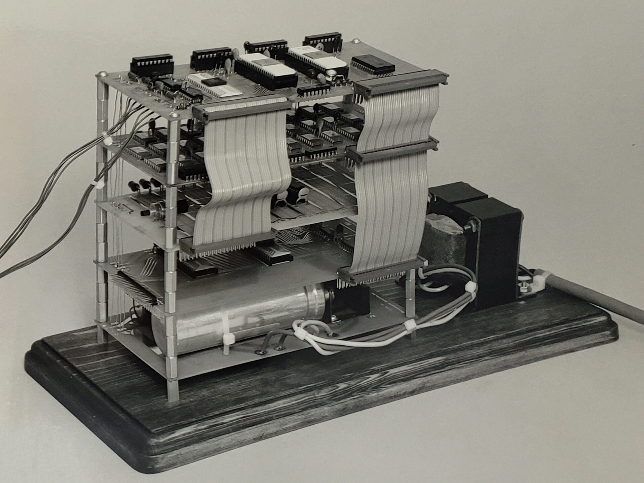
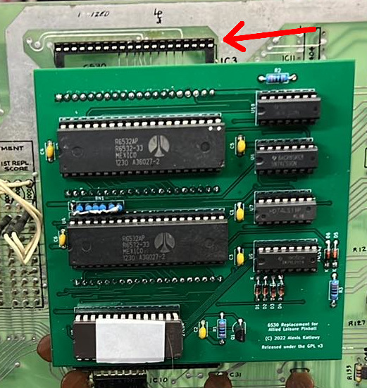
Scott LaLombard software
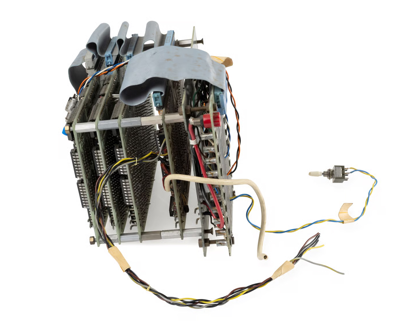
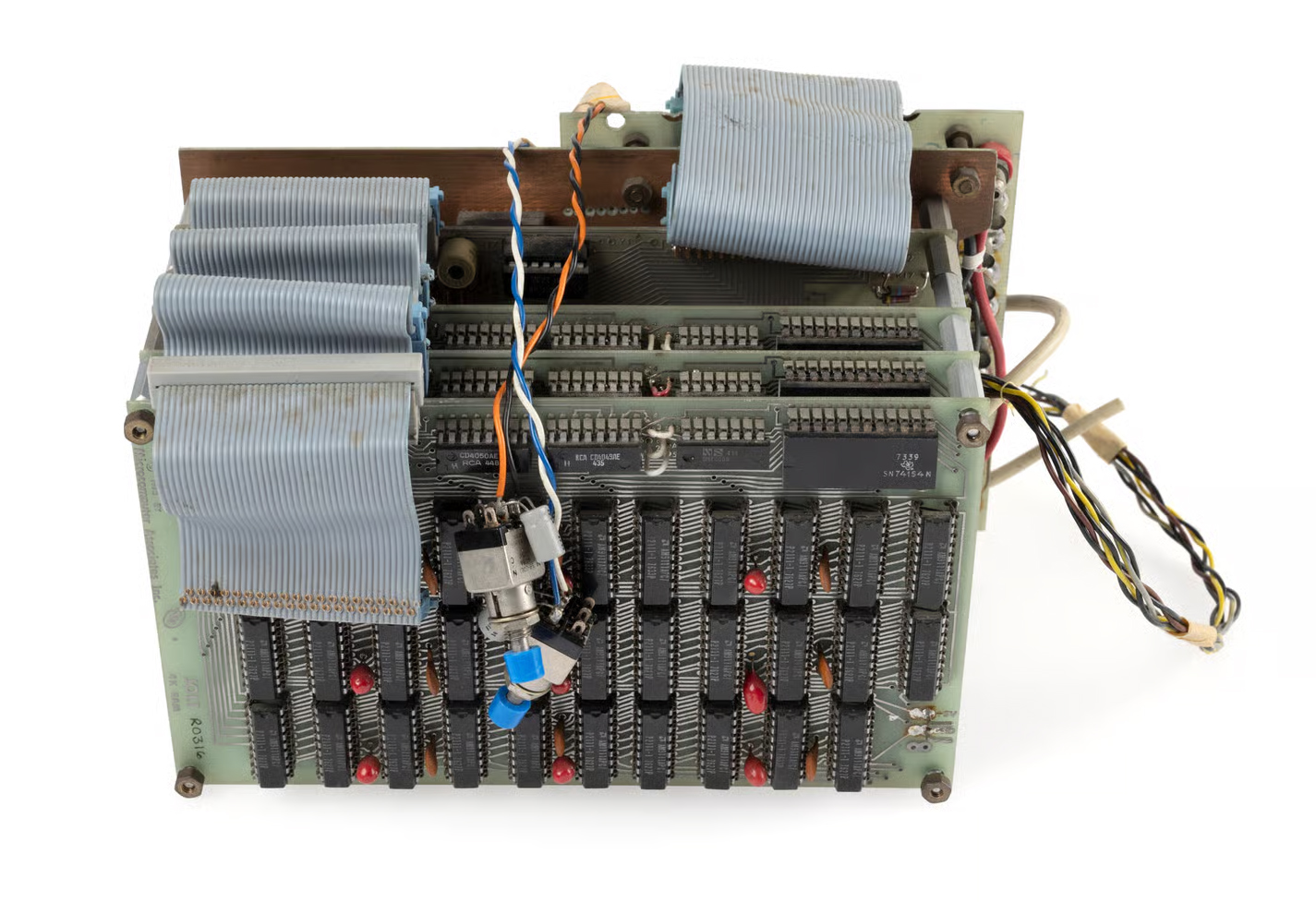
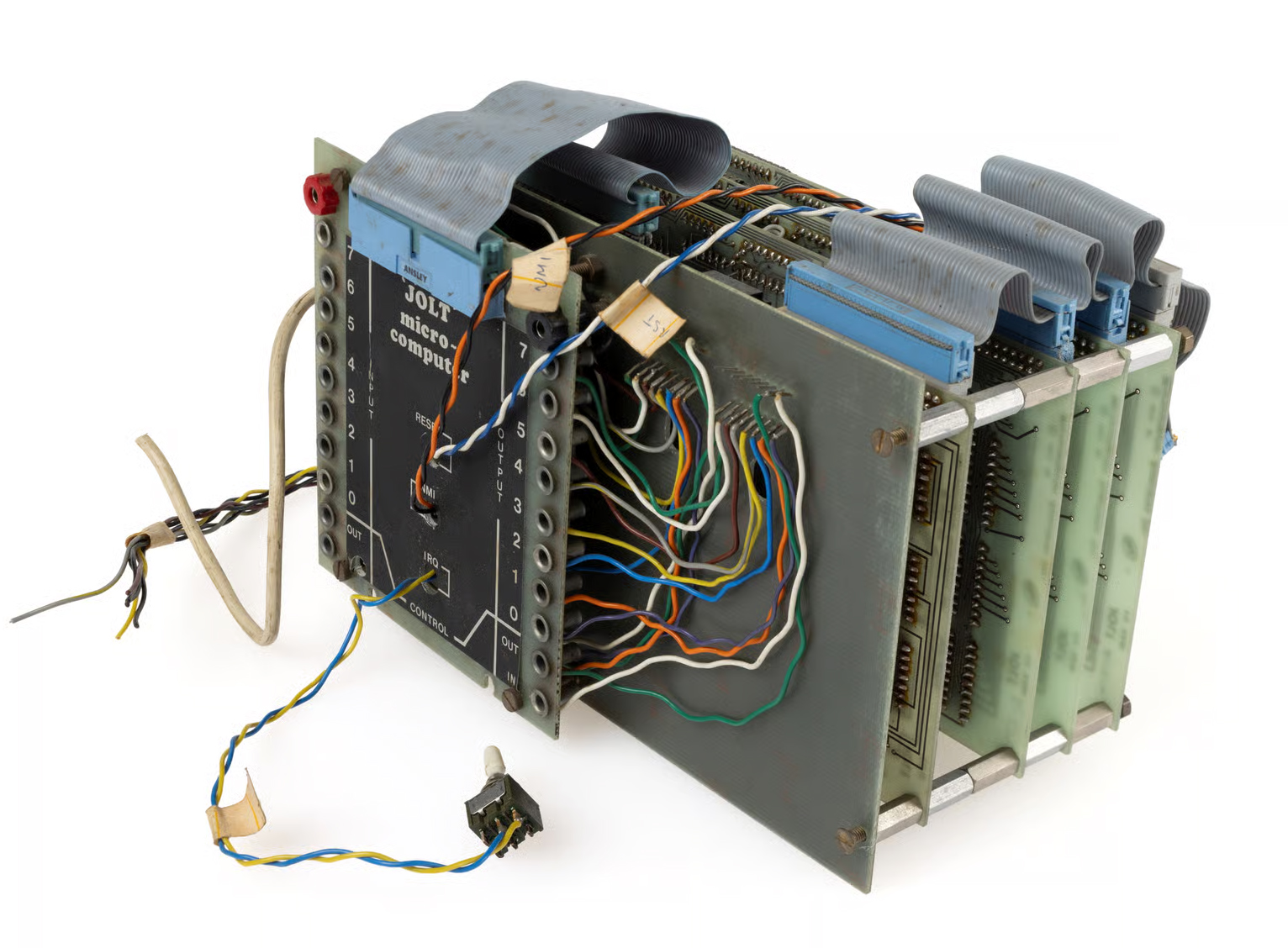
While building a Jolt replica with many expansion boards. Scott Lalombard adapted some software like Tiny Basic. Read about his programs here.
TIM/Jolt Simulator
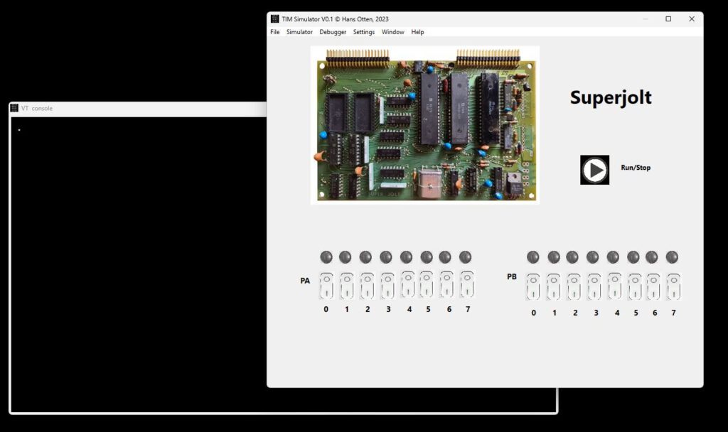
A Jolt/Superjolt/TIM simulator.