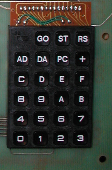
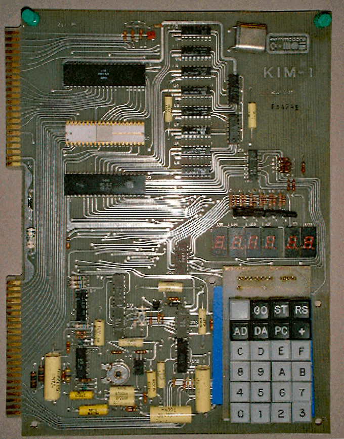
The KIM-1 keyboard is a special one. Made especially for the KIM-1, as you can see in the SST switch. It shows its age in the design, and looks quite familiar to the keyboards hand-held calculators of the 70ties.
In those days replacement keyboards could be bought. I have repaired several KIM-1s with it. The older revisions were worse than what appeared on later revisions.
See also this page about KIM-1 keyboard repair, local copy here.
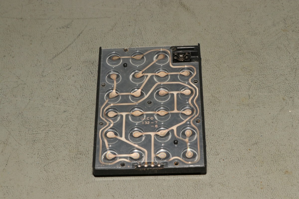
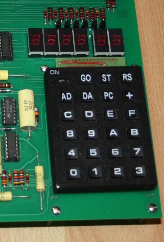
Original KIM-1 version, SST switch on the right.
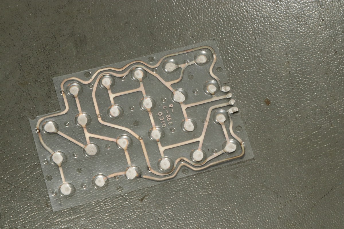
KIM-1 Rev D, SST switch on the left.
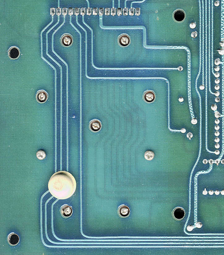
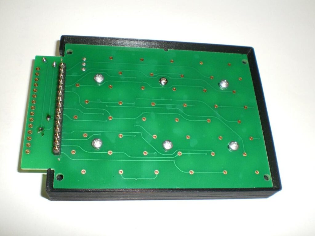
The keyboard is connected to the mainboard with two screws, as you can see on the next image, and the solder connections on the front of the motherboard to the top of the keyboard.
You also see seven holes with access to screws on the bottom of the keyboard. Those keys hold the top of the keyboard connected to the bottom part. Unscrew those seven to get inside the keyboard. Leave the two screws not in a hole alone!
Over time the keyboard may develop problems like stick keys and non-responsive keys. Due to wear or dirty contacts.
A post in the vcfed.org forum may be helpful to fix some of these problems.
User Mindwalker posted this:
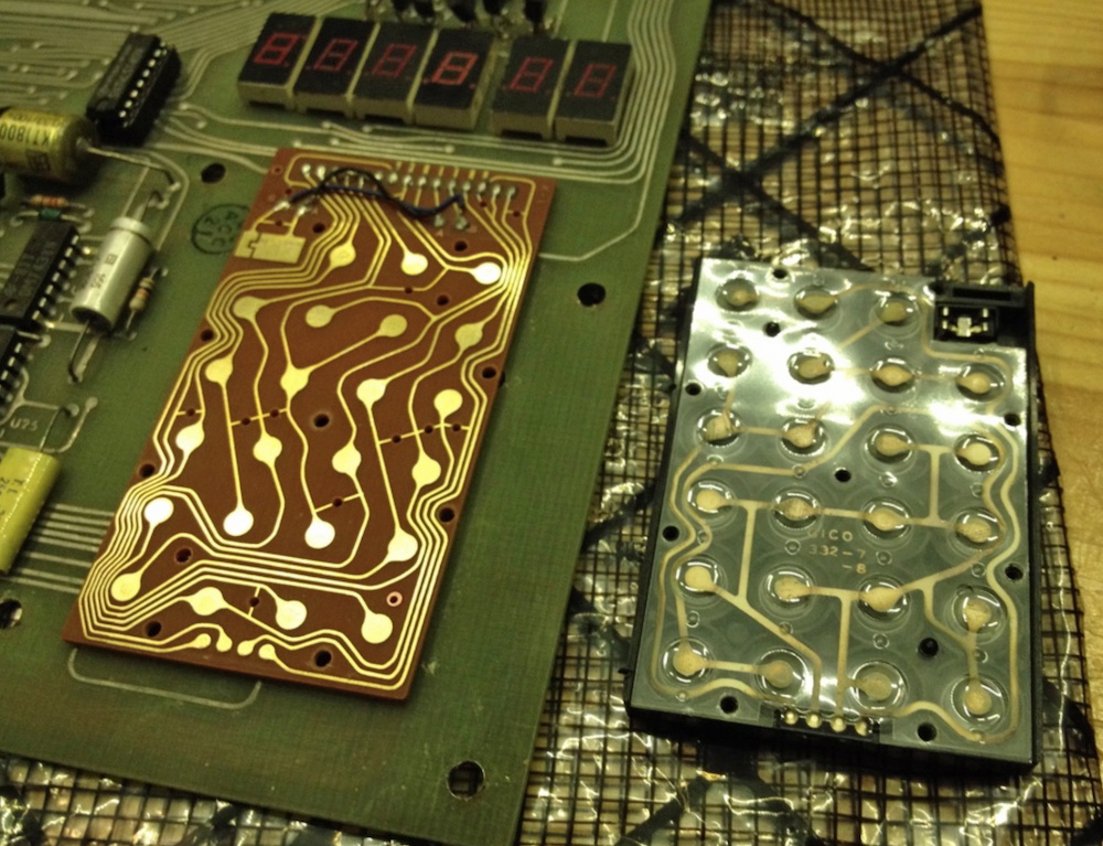
I (mindwalker) remember cleaning the keyboard at one point and I found this picture from my archives.
It seems the key membrane connects to the PCB over four contacts right on the bottom row, you probably have a bad contact there. Cleaning and (carefully) tightening the screws may cure it! Just be careful with the membrane.

Or you could replace the keyboard with other keypads:
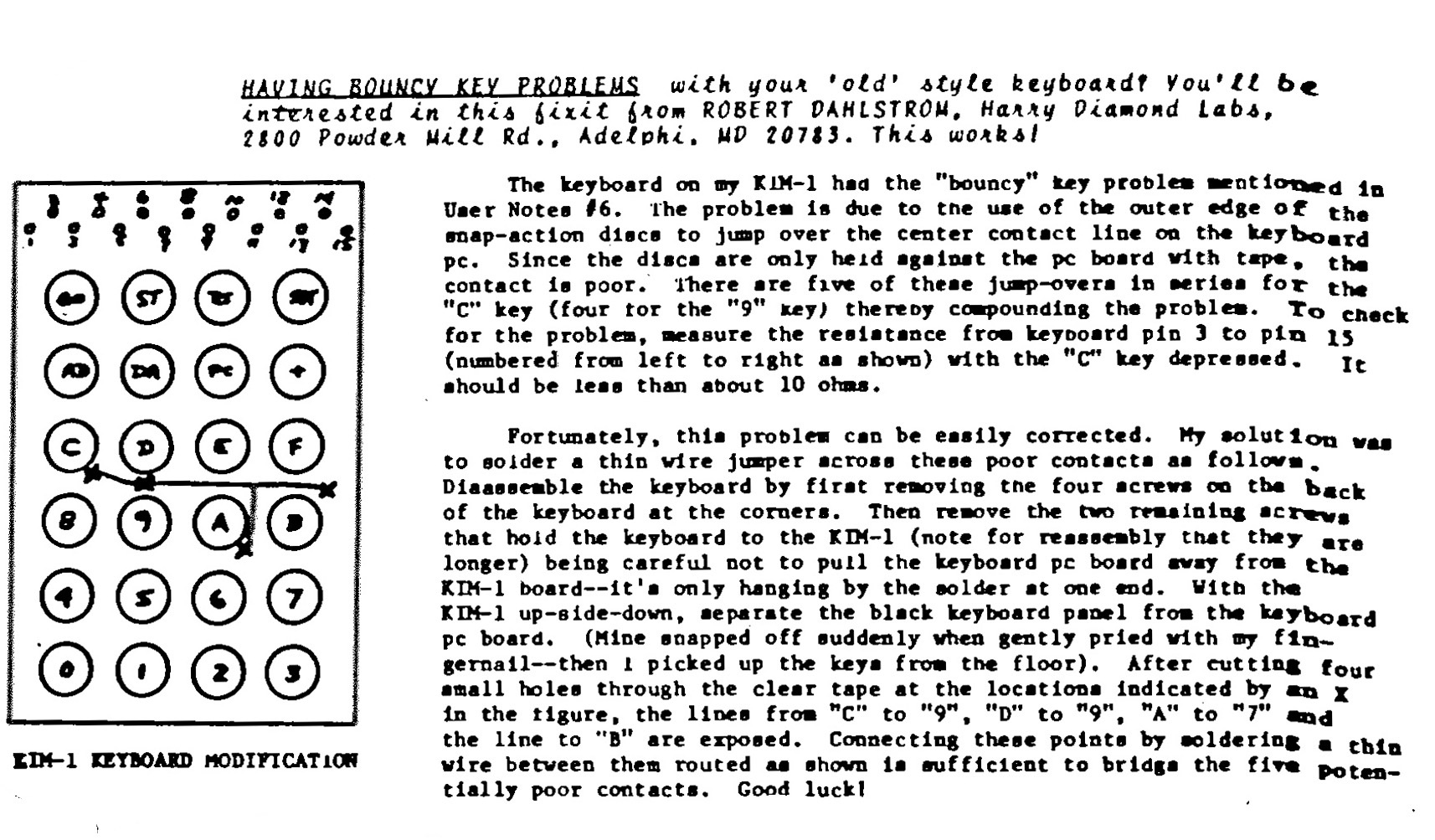
An article in KIM User Notes 10/11 has this advice for the first Revisions key (No Revision, Rev A, Rev B):
Construction of a nearly exact KIM-1 replica keyboard.
Original version: Design, images and original text in German by Ralf (ralf02, forum64.de), from the KIM-1 Aufbau anleitung, and KIM-1 Keypad by user hackup, October 30, 2022 on thingiverse
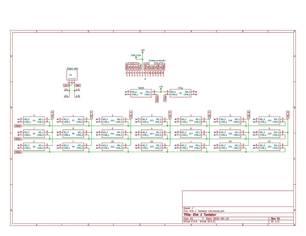
Circuit diagram of the Keyboard PCB
For the keyboard construction you need the following parts:
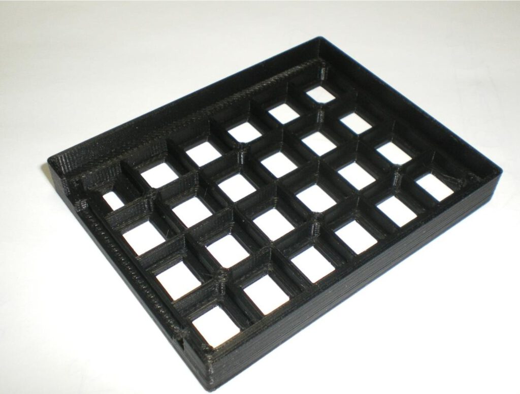
- 1 3D printed keyboard frame, STL from thingiverse
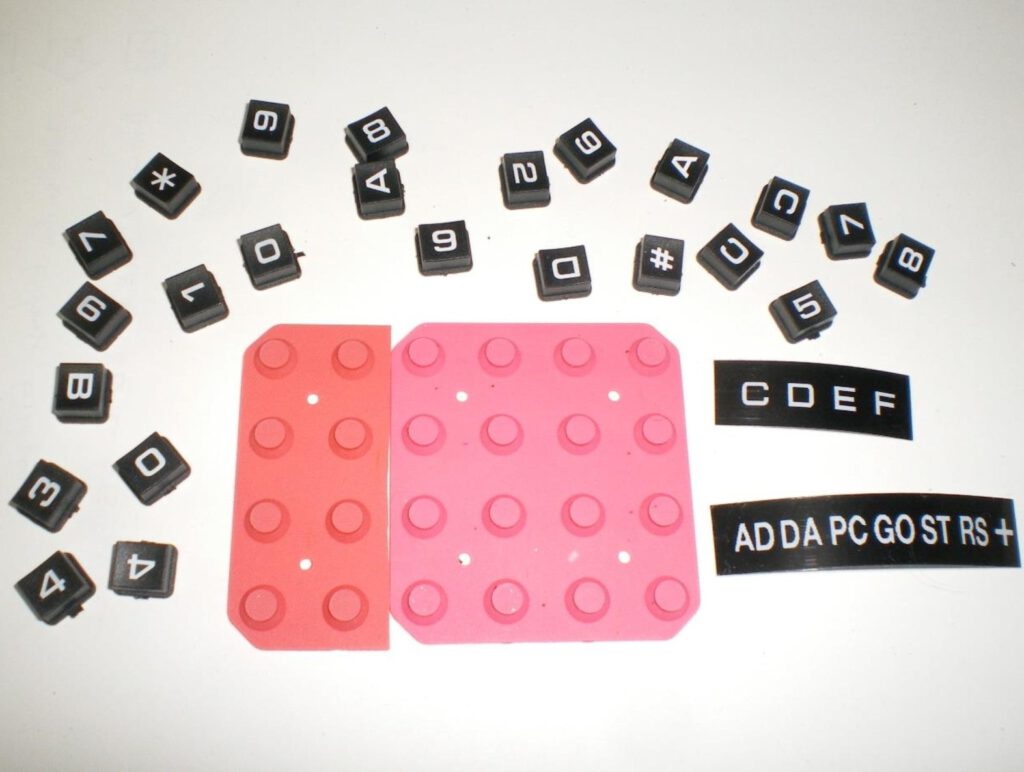
- 2 keypads with 16 keys each as shown (actually, you just need 1 1/2)
- 1 keypad PCB, see the gerber file
- 1 SPDT slide switch, 2.54mm pitch
- 1 female pinheader connector, 15 pins, preferably low profile
- 1 male pinheader, 15 pins to match the female one
- 6 self tapping screws, 2x6mm
- labels printed white on black for the keys E, F, AD, DA, PC, +, GO, ST, RS
- double sided adhesive tape to glue the clips to the motherboard
The keyboard PCB has to be gold plated (ENIG). With tin-plated PCBs the contact from the keys is not reliable.
Downloads made available by Ralf:
- Circuit diagram of keyboard PCB
- Gerber files of PCB
- Label files of keycaps for a Brother printer
- KIM-1 Aufbauanleitung, section on keyboard construction
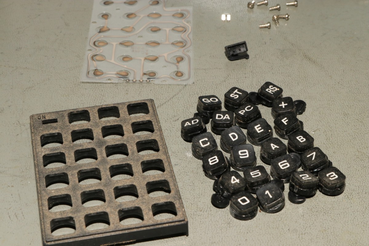
First dismantle the two keyboards and cut the two rubber contact mats as seen in the next picture. Keys 0-0 and A-D have the right lettering, make the other with a letter printer white on black.
Place the keycaps in the 3D printed case:
Now solder the slide switch and the pinheader on the PCB. Cut the rubber mat on the location of the slide swithc. Put the mat in the 3d printed case and fix with 6 screws:
Next place the four M3 screws in the holes in the PCB and the parts in the case. Now place the PCB on the 1 pin pinheader and fix the four screws with washers from the bottom.
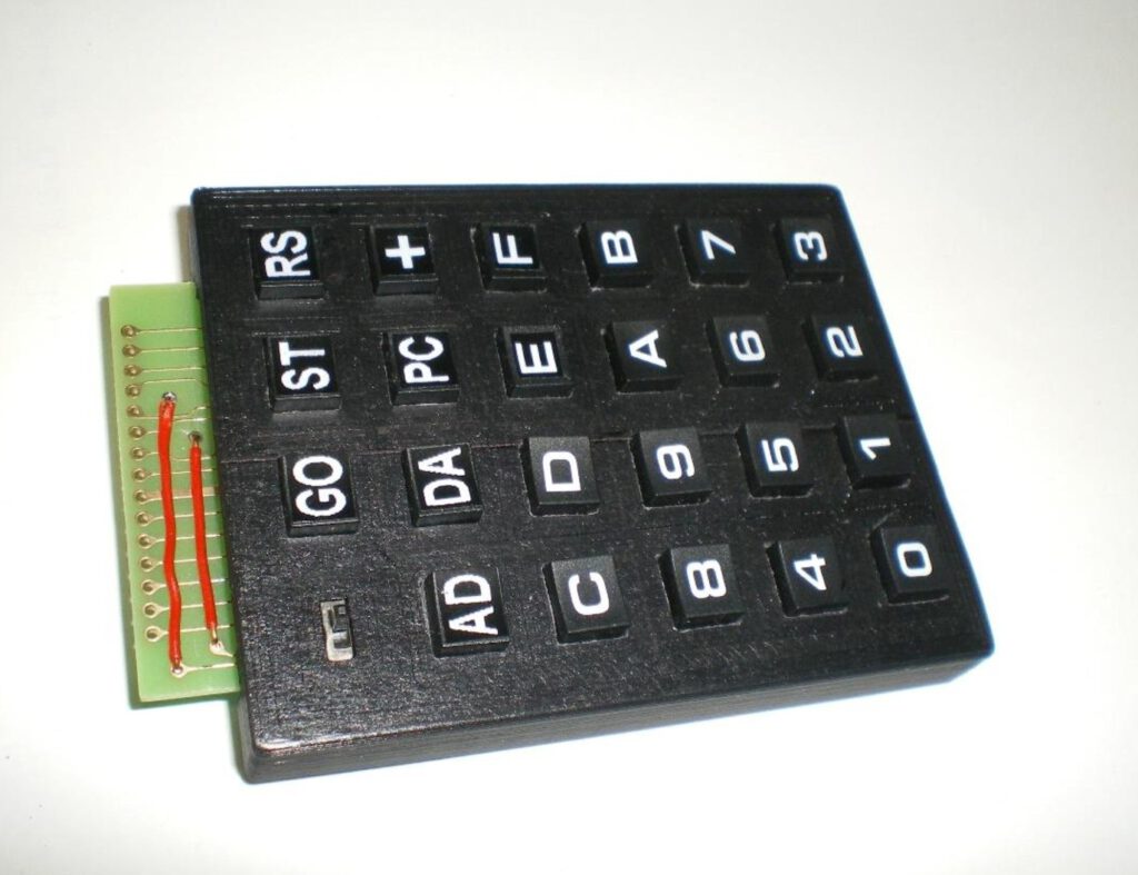
The two red wires are only for decoration, to make it look like as on the KIM-1.