KIM-1 related page update

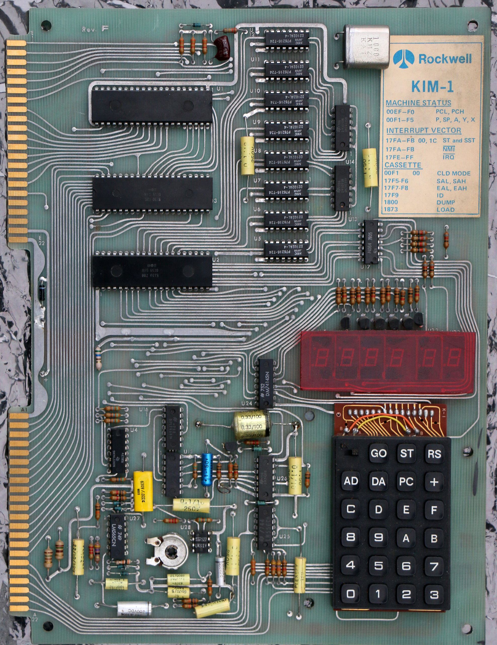
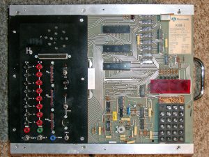
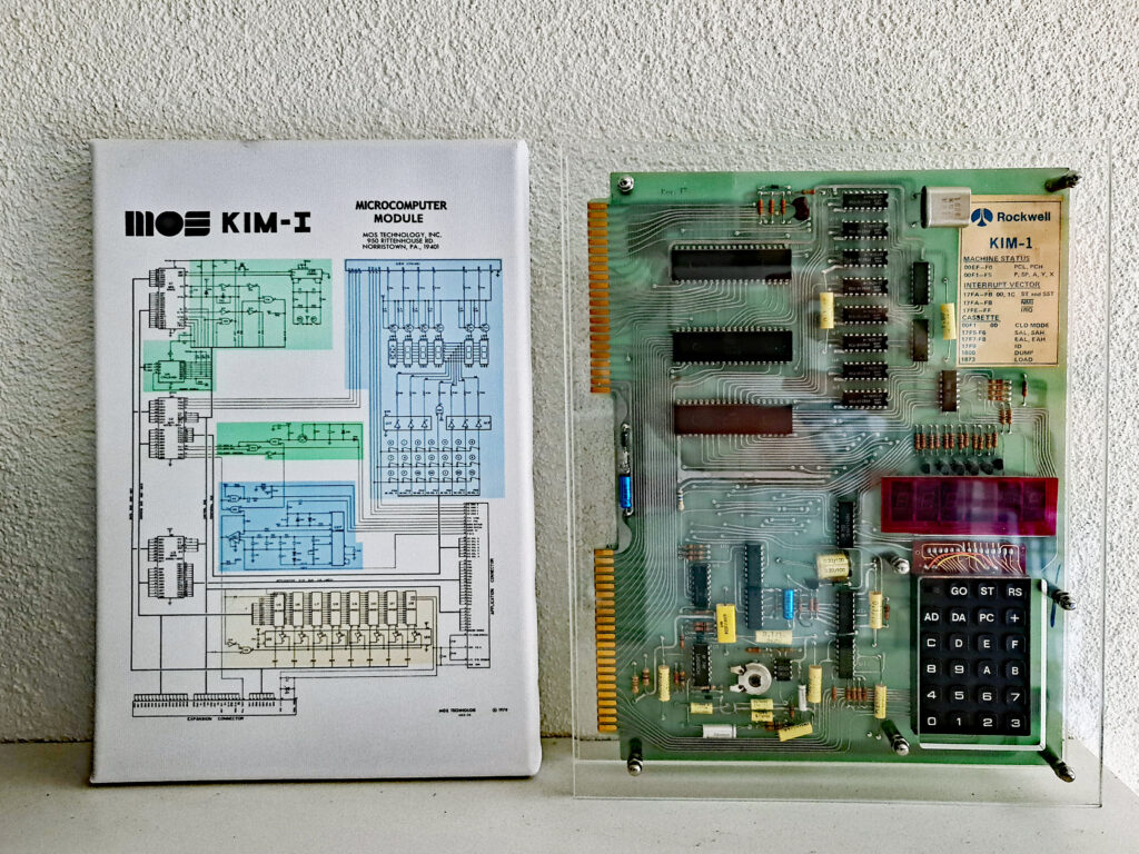
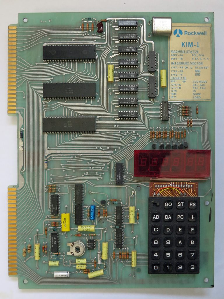
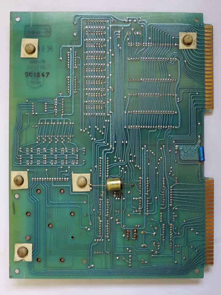
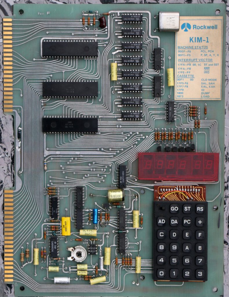
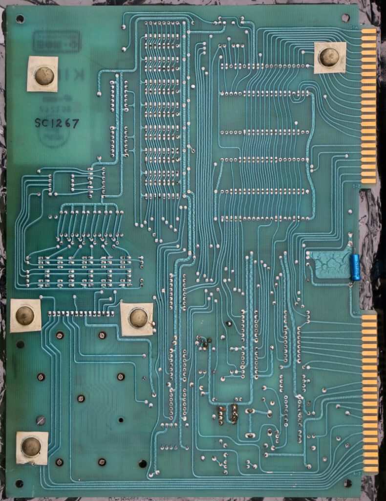
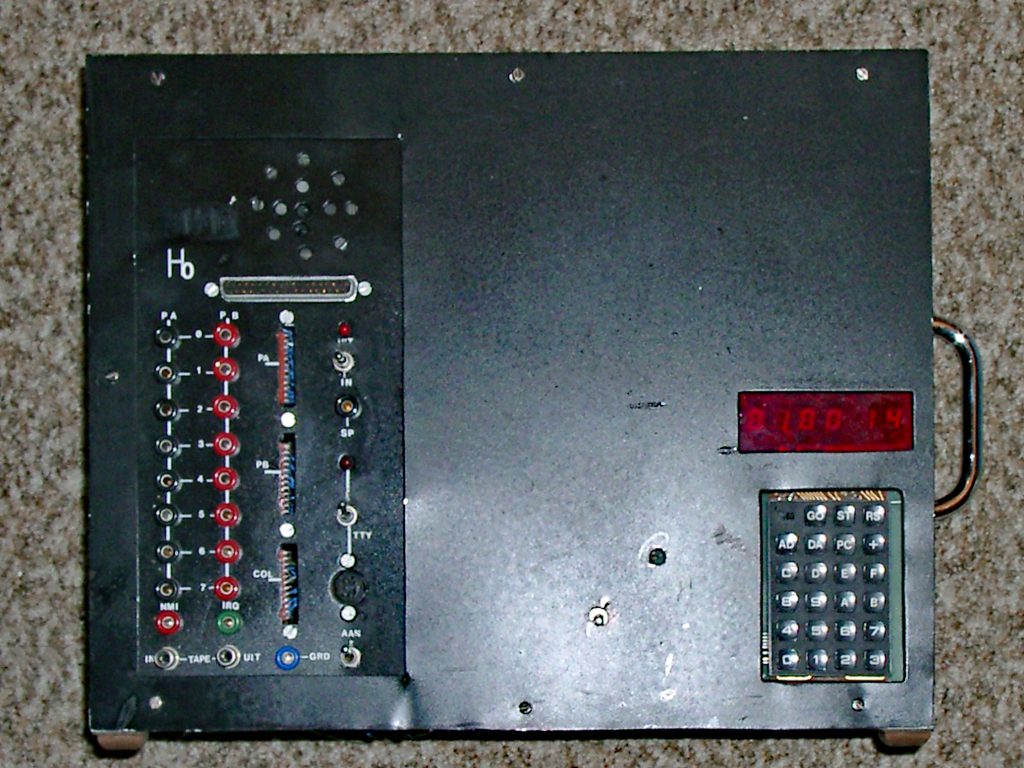
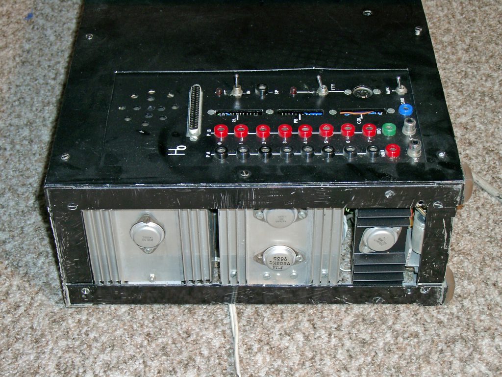
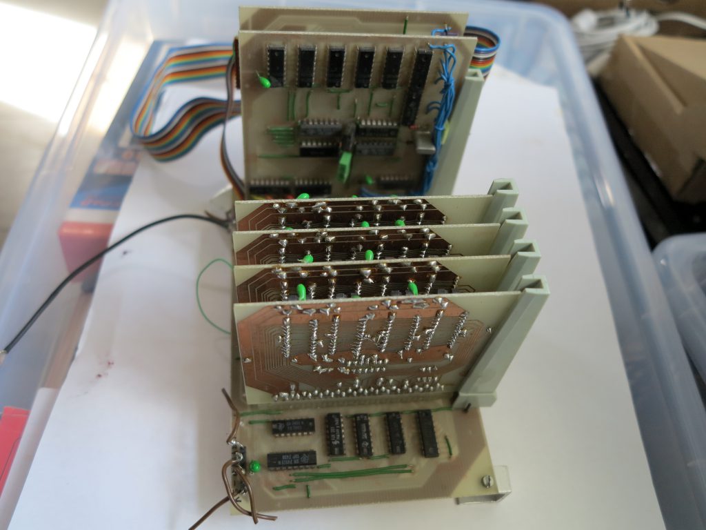
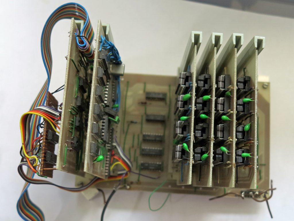
Recently on Ebay a KIM-1 lookalike showed up. The PCB is inspired but clearly newly designed. It is called ‘Scandinavian’ because another identical ‘clone’ had a scandinavian businness sticker on it. Armin Hierstetter bought it and send me photos shown on the “KIM-1 related’ page.

The Data Handler is a SBC (actually two boards!) built in 1975 by Western Data Systems Corporation.One of the first computers based upon the then new 6502, as the KIM-1. Jolt, OSI 300.

post

Data Handler

The Data Handler is a SBC (actually two boards!) built in 1975 by Western Data Systems Corporation.
One of the first computers based upon the then new 6502, as the KIM-1. Jolt, OSI 300.

Photos and blog about this SBC by Armin Zink, who owns a Data handler.

The following text and scans of the manual are by Armin Zink on his blog.

The Data Handler Owner’s Manual Rev. B
The Data Handler Owner’s Manual Rev. C
Data Handler Order Form

To my current knowledge, the first „Data Handler“ Press can be found around June 1976.
The „B“ Manual shows „-2.8-77“. The „C“ Manual said „(c)1976“. While the (c)1975 indicates that it was developed and released much earlier
The „Data Handler“ is a Single Board Computer built in 1975 by „Western Design Systems“ Corporation. The Manual and further Literature name Mr. C.A. Indihar as the founder of Western Design Systems in Santa Clara, California .
Built around the MOS 6502 CPU, it has 1KB static RAM of Type 2102 and a „Front Panel“ with 16 Keys for Hex Entry and 10 Keys to control operation. Data „output“ is realized by 16 LEDS for Address and 8 LEDS for DATA.

  • CL Clear : Clears the Adress or Data Value
  • SC Single Cycle : Executes a single CPU Cycle
  • SI Single Instruction : Runs one operation
  • HT Halt : Stop CPU
  • INT Interrupt/Reset : Start from Reset Vector
  • AD Adress : Change to Modify Adress
  • DA Data : Change to Modify Data
  • EX Examine : Examine Data in an Address
  • RN Run : CPU Run
  • DP Deposit : Store Data

Data Entry into Ram is done via the Front Panel. This may be much easier than operating an MiTS or Altair, but not as comfortable as other SBC with a ROM-Monitor.

There are two I/O Ports on the upper right of the board. One Port for 8-Bit Input and one Port for 8-Bit Data output.

This is the Data Handlers Block Diagram from the REV „C“ Manual. In comparison to the „B“ Version it has an additional Cassette Interface Option. On the RAM Memory there are S-T-R Pins, which are used to split the Memory in 4 Pages.


The board has a Altair compatible BUS Connector, allowing to use one of the many Expansion Cards available for Altair Systems.
Three unpopulated spare sockets are provided for system modification.
To increase system stability, the RC oscillator can be replaced by a Crystal. The SBC needs only one single 5V Supply.
An optional Regulator can be soldered on the back of the board, converting 8V power provided through the Altair Bus or an Altair Power supply to the necessary 5V.

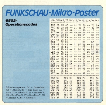
The Manual covers the building and the operation of the Data Handler and also contains the complete Opcode description of the 6502 and the schematics of the board. In the 70s buying a manual for a chip was expensive, so having the 6502 opcodes at hand was convinient. Additionally there is also a section with a instruction lookup table.
A “program section“ contains very few simple programs to start programming.

The bare board was offered for $79, the kit with all parts for $179, so it was half the price of a KIM-1.
The „Data Handler“ was a nice tool to be populated by hobbyists and to learn the Basics of 6502 machine language, but its operation requires some phantasy: Compared to the KIM-1 SBC the Data Handler has NO onboard ROM, PIA or TIA and no Monitor Program.

The „Front Panel“ is a hard wired system to enter data into Ram and start/stop and reset the CPU.
At first the CPU is Reset, then halted, and all inputs have to be cleared.
Then the program is entered in the static RAM locations. If the computation requires input data, these values have to be written in specified memory addresses. Finally you specify the start address of the program in reset vector address $FFFC and $FFFD.
The program execution is started by resetting the CPU. Manual stepping through the instructions allows to verify that the CPU jumps to program start address and runs the program.
If the calculation is finished, the CPU has to be manually halted by pressing „HT“. If there has been results of a computation, these could be viewed by examination of the corresponding memory locations.

In the rear right the we can find the I/O-Section of the SBC. It holds a strobed 8-Bit output and 8-Bit input port. Bytes written at Address 0x7FFE appear at the output port, and input data could be read from 0x7FFF. If attached some LEDS, as instructed in the Manual output could be directly controlled.
Interesting detail: output not necessarily need to be generated by program control , Data entered via the front panel could be stored at 0x7FFE directly and the result could be instantly controlled, giving a very direct response of the system.

The Board is made of 47 TTL Chips plus 8x 1kx1 RAM.
The onboard Ram is located at 0xFC00 and not 0x0000 . To my knowledge (Armin) this disables the use of any Zero Page features like POP/PUSH and indirect Addressing of the CPU. In the manual it is suggested to map RAM expansions to Address 0x0000 to enable all CPU features like Stack.
Since Address decode is done via some Gates, it seems pretty simple to modify the Address Decoder to additionally Map the existing Ram to Adresse $000x and $001x to add these features.

Operation

At first the CPU is Reset and the SI Button should be pressed four times to execute the Reset Sequence.
The program is entered in the static RAM locations. If the computation requires input data, these values have to be written in memory addresses. Additionally the start address of the program has to be stored in reset vector address $FFFC and $FFFD.

The program execution is then started by resetting the CPU. To debug the program, simply press SI-Button to follow the code. The Adress and Data LEDs show the current Program-Step. Additionally you can Cycle through an instruction with the SC-Button, follwing the CPU While fetching or storing Data from or to RAM.

By pressing the (run) RN-Button, the program executes ad maximum speed and preferrably it terminates in an endless loop.

When the calculation is finished, the CPU has to be manually halted by pressing „HT“. If there has been results, these could be viewed by pressing EX-Button and EXamination of the corresponding memory locations.

A FIRST EXAMPLE

Armin tried the 8 Bit Multipy Example from the „Programmes“ Section of the Manual

To Enter the Program, I Pressed HT, CL, AD 0xFFFC, DA 0x00, and DP. So the First Byte of the Reset Vector is entered. The second byte only requires entering 0xFC and DP-Button.

To change the Adress simply Type AD 0xFC00, then DA-Button 0xA2 DP-Button to enter the first Program Byte. Next Byte is 0x08 which is entered via DP-Button. Adress increases automatically after DP-Button is pressed. During the programming process i it is possible to check the entered values via the LEDs. I was astonished how fast i get used to the simple binary display! If you misstyped the DATA, simply reenter, before pressing DP-Button. If i was not sure if the data was entered correctly, i simply retype the adress and start over a bit earlier. After i finished the program we have to deposit the two values required by the test program „Multiplicand“ and „Multiplier“ in 0xFD00 and 0xFD01. Simply Type AD 0xFD00, AD 0x02, and DP. In my test i used 0x02 for Multiplier and Multiplicand 0xFD01. This simply represents Multiply 2 by 2, and we expect 4 as a result. To verify the entered data, I used the sequence HT-SI-EX-AD 0xFD00.

To start the CPU, I pressed INT, and single-stepped through it with the single Instruction SI-Key. After some cycles the programm halted in the endless loop in 0xFC1F. By pressing HT EX 0xFD02 I could examine the result: The data LEDs „Display“ showed 0x04 ! Yippie. First Program Run Completed..!

EXPANSION

In the rear right the we can find the I/O-Section of the SBC. It holds a strobed 8-Bit output and 8-Bit input port. Bytes written at Address 0x7FFE appear at the output port, and input data could be read from 0x7FFF. If attached some LEDS, as instructed in the Manual, output could be directly controlled.

Interesting Detail: Output not necessarily need to be generated by program control: Data entered via the front panel could be stored at 0x7FFE and the result could be instantly controlled at the PIA Port without CPU Control, giving a very direct system response.

The Board is made of #47 TTL Chips plus 8x1k-RAM. The onboard Ram is located at 0xFC00 not 0x0000 to allow modification of the RESET and Interrupt Vectors.
To my knowledge this disables the use of Zero Page features like Stack (POP/PUSH), Subroutines JSR/RET, Complete Zero Page Storage and all indirect Addressing of the CPU. Only to set the Reset Vectors in Ram…Strange.

In the manual it is strongly suggested to map RAM expansions to Address 0x0000 to enable all CPU features.
Work-Around: Since Address decode is done via some Gates, it seems pretty simple to modify the Address Decoder to additionally Map the existing Ram to Adresse $00xx and $01xx to add Stack and Zero Page features.

Update August 2022: In the REV C Manual, the Manufacturer describes a Modification of the Board, which separates the 1k Memory in 4 Pages. A Jumper R,S,T, is installed which allows to Map parts of the Memory to Page 0x00,0x01 and 0xFE and 0xFF. So the System can use the Zero Page Features of the CPU.

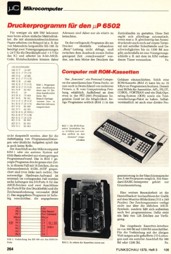
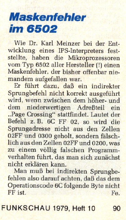
Original MOS CPU Card
The unit came with an original MOS 6500 CPU Instruction Set Summary Card, attached is a WDS Stamp.


People’s Computers 1976

Articles in People’s Computers about the Data Handler
Original advertisement Data Handler
post

Amateur Radio

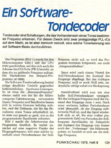
Amateur Radio February 1978 Looking for a Micro? – consider the KIM-1

post

Popular Electronics

Articles and advertisement, from 1977 to 1980


1977 07 08 10 Build the TVT-6, a Low-cost Direct Video Display

1977 07 08 10
Build the TVT-6, a Low-cost Direct Video Display

1977 12 Advertisement Play it Safe KIMPAC

1977 12
Advertisement Play it Safe KIMPAC

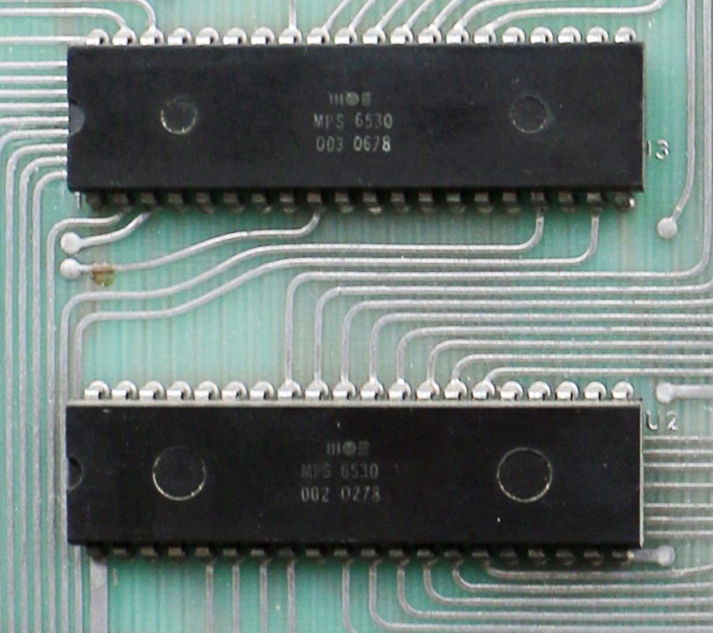
1977 12 Advertisement KIM-1 6530-003 003 004 005

1977 12 Advertisement
KIM-1 6530-003 003 004 005

1977 12 Advertisement KIM-1

1977 12 Advertisement KIM-1

1978 03 6502 Executive for KIM-1

1978 03 6502 Executive for KIM-1

1978 04 FCL65E High-Level Language for 6502

1978 04 FCL65E
High-Level Language for 6502

1978 07 KIM-1 Extended I/O Monitor XIM

KIM-1 Extended I/O Monitor XIM

1978 07 Advertisement KIM-1 KIM-3B KIM-4 KIM-5 KIM-6

1978 04 Advertisement
KIM-1 KIM-3B KIM-4 KIM-5 KIM-6

1978 07 Advertisement Memory Plus

1978 07 Advertisement Memory Plus

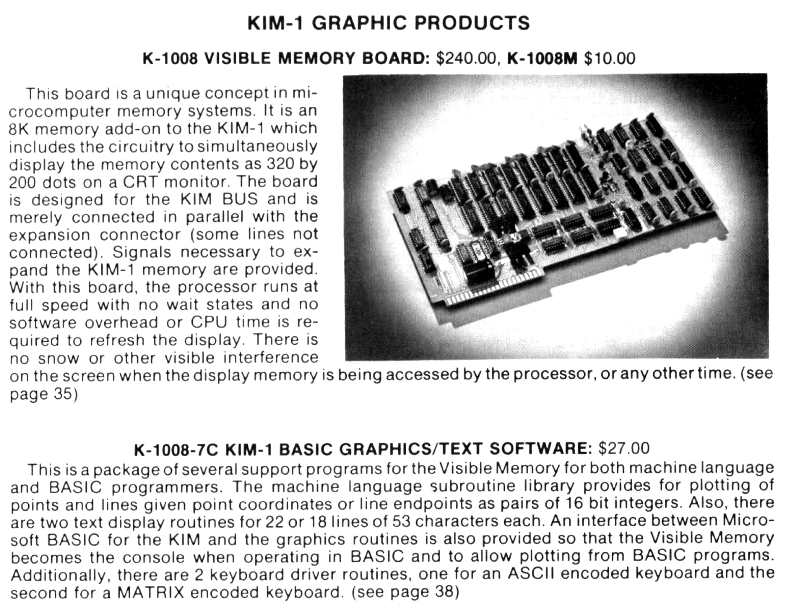
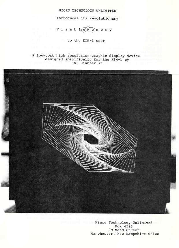
1978 08 Advertisement KIM-1 KIMSI, KIM-4 Enclosure 8K Visible Memory

1978 08 Advertisement
KIM-1 KIMSI, KIM-4 Enclosure
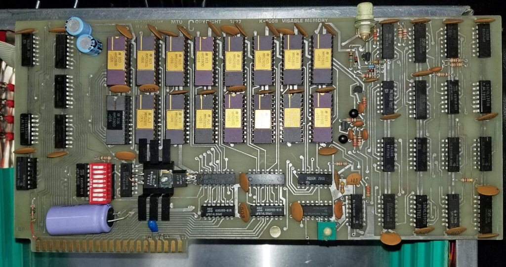
8K Visible Memory

1978 08 Advertisement VIM-1

1978 08 Advertisement VIM-1

1978 09 Multiply and Divide 6502

1978 09 Multiply and Divide 6502
post

Byte Magazine

Articles and advertisements from Byte Magazine related to the 6502 in general and the KIM-1.


Byte Magazine 1975 11 Son of Motorola (or, the $20 CPU Chip)

Byte Magazine 1975 11 Son of Motorola (or, the $20 CPU Chip)

Byte Magazine 1975 12 Introducing Jolt .. the world lowest cost computer system


Byte Magazine 1976 01 Introducing Jolt .. the world lowest cost computer system


Byte Magazine 1976 04 What’s New, KIM-o-sabee


Byte Magazine 1976 05 A Date with KIM

Byte Magazine 1976 05 A Date with KIM

Byte Magazine 1976 08 How I relate to KIM True Confesssions

Byte Magazine 1976 08 How I relate to KIM True Confesssions

Byte Magazine 1977 03 A opcode Table for 6502

A opcode Table for 6502

Byte Magazine 1977 04 A Review of Tom Pitman’s Tiny basic

Byte Magazine 1977 04 A Review of Tom Pitman’s Tiny basic

Byte Magazine 1977 04 KIM goes to the Moon

Byte Magazine 1977 04 KIM goes to the Moon, Jim Butterfield

Byte Magazine 1977 06 Interfacing the IBM Selectric Keyboard Printer

Byte Magazine 1977 06 Interfacing the IBM Selectric Keyboard Printer

Byte Magazine 1977 06 Come Fly with KIM

Byte Magazine 1977 06 Come Fly with KIM

Byte Magazine 1977 07 Giving KIM Some Fancy Jewels


Byte Magazine 1977 09 A Sampling of Techniques for Computer Performance of Music

Byte Magazine 1977 09
A Sampling of Techniques for Computer Performance of Music
Hal Chamberlin

Byte Magazine 1977 09 A new Dress for the KIM


Byte Magazine 1977 10 Use S-100 Boards with your KIM-1 advertisement

Use S-100 Boards with your KIM-1 advertisement

Byte Magazine 1977 10 Chess program for SOL and KIM-1

Chess program for SOL and KIM-1

Byte Magazine 1977 11 Advertisement KIM Meets S-100

Byte Magazine 1977 11 Advertisement KIM Meets S-100

Byte Magazine 1977 11 Sweet 16 Steve Wozniak

Byte Magazine 1977 11 Sweet 16 Steve Wozniak

Byte Magazine 1977 11 A 6502 Personal System Design: Kompuutar

Byte Magazine 1977 11 A 6502 Personal System Design: Kompuutar

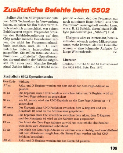
Byte Magazine 1977 12 The XF and X7 Instructions of the MOS Technology 6502

Byte Magazine 1977 12 The XF and X7 Instructions
of the MOS Technology 6502

Byte Magazine 1978 02 Sweets for KIM A Low calorie Text Editor

Byte Magazine 1978 02
Sweets for KIM A Low calorie Text Editor

Byte Magazine 1978 03 Microchess 1.5 versus Dark Horse


Byte Magazine 1978 03 KIMSI

Byte Magazine 1978 03 KIMSI

Byte 1978 06 More Music for the 6502


Byte 1978 06 Audio Processing with a Microprocessor

Byte 1978 06
Audio Processing with a Microprocessor

Byte 1978 07 KIMER: A KIM-1 Timer


Byte Magazine 1978 09 Plugging the KIM-2 Gap

Byte Magazine 1978 09 Plugging the KIM-2 Gap

Byte Magazine 1978 11 KIM-1 advertisement

Byte Magazine 1978 11 KIM-1 advertisement
Commodore MOS Technology

Byte Magazine 1978 12 SUPERKIM advertisement

Byte Magazine 1978 12 SUPERKIM advertisement

Byte Magazine 1978 12 A Single Board Microcomputer System SYM-1

Byte Magazine 1978 12
A Single Board Microcomputer System SYM-1

Byte Magazine 1978 12 Zapper A Computer Driven EPROM Programmer

Byte Magazine 1978 12
Zapper A Computer Driven EPROM Programmer

Byte Magazine 1979 01 RNB Enterprises SYM-1 KIM-1 VAK-X boards advertisement
Byte Magazine 1979 01
RNB Enterprises SYM-1 KIM-1
VAK-1to VAK-8 boards advertisement

Byte Magazine 1979 01 Jade Computer Products
Byte Magazine 1979 01 Jade Computer Products
SYM-1 KIM-1 6502 6530-002 – 003 -004 -005 IC’s

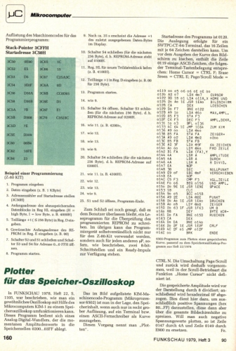
Byte Magazine 1979 02 1980 02 Another Plotter to Toy with, Revisited
Byte Magazine 1979 02 1980 02
Another Plotter to Toy with
Another Plotter to Toy with, Revisited

Byte Magazine 1979 02 Cosmac 1802 Simulator for KIM-1

Byte Magazine 1979 02 Cosmac 1802 Simulator for KIM-1

Byte Magazine 1979 03 MICROCHESS advertisement

Byte Magazine 1979 03 MICROCHESS advertisement

Byte Magazine 1979 05 Aids for Hand Assembling Programs

Byte Magazine 1979 05
Aids for Hand Assembling Programs

Byte Magazine 1979 06 Software for Jolt and TIM owners

Byte Magazine 1979 06
Software for Jolt and TIM owners

Byte Magazine 1979 06 KIM-1 Control System

Byte Magazine 1979 06 KIM-1 Control System

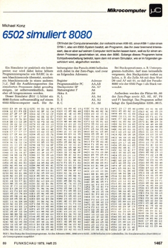
Byte Magazine 1979 07 8080 Simulator for the 6502

Byte Magazine 1979 07 8080 Simulator for the 6502

Byte Magazine 1979 08 Turn Your KIM into a Metronome


Byte Magazine 1979 09 Interface a Chessboard to Your KIM-1

Byte Magazine 1979 09 Interface a Chessboard to Your KIM-1

Byte Magazine 1980 03 KIM-1 Multiplication and Division

Byte Magazine 1980 03 KIM-1 Multiplication and Division

Byte Magazine 1980 03 You Win! with Sybex

Byte Magazine 1980 03 You Win! with Sybex

Byte Magazine 1980 04 Advanced Real-Time Synthesis Techniques

Byte Magazine 1980 04
Advanced Real-Time Synthesis Techniques
Hal Chamberlin

Byte Magazine 1980 04 Program Those 2708s!

Byte Magazine 1980 04 Program Those 2708s!

Byte Magazine 1980 06 An Answer/Originate Modem

Byte Magazine 1980 06 An Answer/Originate Modem

Byte Magazine 1980 09 Penny Pincher’s Joystick Interface

Byte Magazine 1980 09 Penny Pincher’s Joystick Interface

Byte Magazine 1980 06 The Impossible Dream

Byte Magazine 1980 06
The Impossible Dream
Computing e to 116,000 places with a Peroanl Computer
Stephen Wozniak

Byte Magazine 1980 10 The 6502 gets Micro programmable Instructions

Byte Magazine 1980 10 The 6502 gets Micro programmable Instructions

Byte Magazine 1980 12 Monster Combat

Byte Magazine 1980 12 Monster Combat

Byte Magazine 1980 10 Floptran IV: A Tiny Compiler

Byte Magazine 1980 10 Floptran IV: A Tiny Compiler

Byte Magazine 1981 10 A Simple Implementation of Multitasking

Byte Magazine 1981 A Simple Implementation of Multitasking

Byte Magazine 1981 05 06 Build a Super Simple Floppy Disk System

Byte Magazine 1981 Build a Super Simple Floppy Disk System

Byte Magazine 1981 06 An Easy to Use AD converter

Byte Magazine 1981 06 An Easy to Use AD converter

Byte Magazine 1981 06 198106 An Impossible Dream, Steve Wozniak Computing e

Byte Magazine 1981 An Impossible Dream, Steve Wozniak
post

KIM-1 and 6502 in magazines

The Story of TIM and KIM

Additions tot the TM and KIM-1 information:

The story Of TIM (documenting the work by Ray Holt and Manny Lemas

The Story of the KIM-1

(from Ch.1.5 of “On the Edge: the Spectacular Rise and Fall of Commodore”)

post

The story of the KIM-1

The story of the KIM-1 (from Ch.1.5 of “On the Edge: the Spectacular Rise and Fall of Commodore”)

MOS Technology developed a second system concurrently with the TIM. This computer was slightly more user friendly – at least by 1975 standards. Rather than a chip and some instructions, this system arrived fully assembled, except for the power supply. It was a true development system.
The inspiration for the new computer came from Don McLaughlin, MOS Technology founder and engineering manager of the project. Peddle recalls, “McLaughlin said, ‘Listen, I think this is a product that will help sell the [6502]’. They thought it was a good idea because they were calculator guys.” Peddle and a programming manager named Bob Winterhalt agreed with the idea and the three men began the design.
According to MOS Technology employee Al Charpentier, his friend and fellow engineer performed the actual hands-on design work of the system. “That was done by a guy by the name of John May,” recalls Charpentier. “He was sort of the primary mover on that project.”
At this early stage in microcomputer development, user-friendly personal computers were barely on the horizon. Niceties like a video monitor, keyboard, software, power supply, or an enclosure were not part of most designs. The recently released Altair relied on switches for input and blinking lights for output. Any other interfaces had to be added by the user. By today’s standards, it was comically impossible for most people to contemplate using these machines.
This new sibling of TIM would share similarities, but differ in a few areas. As with the TIM, this unit would contain a 6502 processor running at one megahertz. However, McLaughlin advanced TIM’s basic design slightly, branching out in a unique direction. Instead of reading data from a row of flashing lights, the new computer would contain a six-digit display. Each digit in the display had seven segments, which could display numbers and letters. The primitive display was a step up from tiny lights representing binary digits used on most other systems. McLaughlin also improved on the basic input method for personal computers at the time. Rather than a row of switches for binary input, McLaughlin specified a keypad. John May eventually selected a black keypad with 23-buttons. This was a remarkable improvement over other microcomputers of the time, allowing users to enter code more easily.

Both the keypad and the LED display reside directly on the surface of the printed circuit board (PCB), along with over a hundred precariously exposed components. The lack of a case or a power supply for the new computer clearly indicated MOS Technology was not targeting the machine for the mass market. A careless user could easily damage the machine..
Little TIM provided a paltry 256 bytes of memory, hardly enough to store three lines of characters on an 80-character computer display. TIM’s bigger brother would contain a full kilobyte of memory, comprised of eight MOS Technology 6102 memory chips. At the time, 1024 bytes was a generous amount. There was even room for expansion. Two 44-pin edge connectors made data and control signals available to the builder for additional functionality.

Prototype KIM-1
On team6502  I found a photo of a prototype KIM-1 at MOS Technologies, Terry Holdt has this in his office.
The layout is different from the final product, everything seems to be present on this prototype.

Although the two development teams were separate, they shared as much code as possible. To support a teletype machine, John May used the code from the TIM system. The 2-kilobyte program, also named TIM, contained the code to operate a cassette tape unit for storage, drive the alphanumeric display, and accept input from the 23 keys of the keypad. It also contained a monitor program, which allowed users to view memory contents and change code. A tiny bootstrap program would automatically start the monitor on reset. This was the pinnacle of user friendliness in 1975.
The name for this new computer followed the tradition set by TIM. The TIM allowed input from a terminal, hence Terminal Input Monitor. The new system allowed input from a tiny black keyboard, so McLaughlin dubbed it the Keyboard Input Monitor, or KIM. They also added a number after the computer name, a practice later continued by Commodore. It contained one kilobyte of memory, hence KIM-1. 2
Former MOS Technology engineer Robert Yannes owns the first KIM-1. “I have a very rare thing that I scavenged out of scrap heap at MOS Technology: the original prototype KIM-1, and it still works. It’s a little bit different than what went into production,” he says.

In the middle of 1975, MOS Technology began selling the KIM-1. Buyers who sent away for their KIM-1 were pleasantly surprised to have a rectangular cardboard box arrive from “MOS Microcomputers”, a short-lived division of MOS Technology. The KIM-1 circuit board arrived sealed in a black static-proof bag, surrounded by thick foam padding with manuals and documentation on top. The documentation included with the KIM-1 went beyond other computers of the day. There were three manuals – a 200-page 6502 programming manual (written by Peddle under duress), a 100-page KIM-1 user manual, and a 150-page hardware manual. The writing was friendly, concise, and detailed. Most importantly, it did not assume the user knew everything about computers already. The KIM-1 user manual promised, “You should be able to achieve initial operation of your KIM-1 module within a few minutes.” Of course, this assumed you had access to a 5 volt, 1.5 ampere power supply. A 12 volt supply was required if the cassette tape was to be used. For those in doubt, the manual contained complete instructions and a parts list for building a power supply. Once the power supply dilemma was solved, the user hit the RS (reset) key to start using the system. This started the TIM monitor program running from ROM, which displayed numbers and accepted input from the keypad. Unlike today’s systems, the KIM-1 contained no on-off switch.
Users then began the exacting process of entering code into the machine in order to make KIM do something. After entering all the data, it was simple to run the program – just set the computer to the address where the program began and hit the GO button. If the program misbehaved, the KIM-1 also had a switch on the keypad labeled SST (single step). This would cause the computer to execute the program one instruction at a time. Users appreciated this important feature, which greatly assisted in debugging.
The built in cassette-tape interface of the KIM-1 proved indispensable for early hobbyists because it allowed them to save and load their work. In contrast, users of the MITS Altair had no way to save programs with their basic system. They would sit in front of their machine, laboriously flipping switches to enter their program into memory. If someone happened to trip on the power cord, the programmer had to start all over again.
The tape-interface alone made many KIM-1 owners fall in love with the computer, and many praised it for its reliability. Tape storage was the perfect medium for a 1-kilobyte computer. Programs loaded and saved rapidly, and dozens of programs fit onto a single cassette. Of course, a cassette recorder was not included with the KIM-1, so it was up to the user to find one. It was also up to the user to connect it to the KIM-1 by interfacing the microphone input and speaker output jacks to the gold-plated IO pins of the KIM-1.
Another advanced feature of the KIM-1 was its ability to connect directly to a Teletype machine or computer terminal through a built-in serial interface. Teletype machines were large electromechanical devices with the ability to enter data through a keyboard, print hard copy, and load and save data via punched paper tape. A noteworthy feature of the KIM-1 was its ability to automatically adjust to the speed of the teletype connected to it. People were amazed to see the tiny KIM-1 operating a massive piece of hardware normally connected to minicomputers or mainframes. This helped to convince skeptics that microcomputers were true computers. As it turned out, however, many people preferred using the LED display and keypad to the noisy, messy, and costly teletype machines.

The KIM-1 debuted during Wescon in Chuck Peddle’s hotel suite, along with the 6502 and other development systems. Users received the small computer enthusiastically. Al Charpentier recalls, “They sold a lot of those. It was sort of the first fully packaged microcomputer that you could take out of the box, throw a power supply on, and do something with. It was hell, but it educated people on the processor.”
Engineer Robert Yannes recalls KIM-1 engineer John May showing the machine at his college. “I had a lot of familiarity with the KIM-1,” says Yannes. “The guy who designed that was actually a friend of Al Charpentier’s, and he was a Villanova graduate too. He had brought it to Villanova University when it first came out and I had gone to that presentation. They had KIM-1’s at Villanova too, so I ended up playing with them.”
“The KIM-1 had one characteristic that everybody always commented on,” says Peddle. “It was a packaged, complete, plug-it-in-and-start-using-it product. You could sit down and learn to program using my manuals.”

Early Competition

In December 1975, the coveted inside front cover of BYTE magazine contained a two-page advertisement for ‘the world’s lowest cost computer system’. Though it contained a 6502 microprocessor, it was not the KIM-1. It was the Jolt computer, sold by Microcomputer Associates either as a kit for $249 or fully assembled and tested for $348. Jolt, named after Rod Holt who helped develop the TIM and KIM-1 code, was technically similar to the TIM computer. Although Jolt competed with the KIM-1, Peddle did not object. “Manny just said, ‘We want to do this board of our own’, and I said ‘great’”, explains Peddle. “I was looking for anything that would help customers design with the [6502] product. We gave these guys the license.” Nonetheless, Jolt did not have lasting popularity with the hobbyist market. Jolt’s most notable achievement lies in its use as the platform for the Atari 2600 VCS prototype system.
The Jolt advertisement in Byte did much to influence MOS Technology. A few months later, in the April 1976 issue of BYTE Magazine, a new product announcement appeared for the KIM-1 titled, ‘What’s New, KIM-o-sabee?’ There was also an advertisement from MOS Technology itself. The low-key ad, stating the features in KIM-1 in point form, included a clip-out order form for a $245 KIM-1 microcomputer system. Anyone who understood computers recognized the potential immediately.
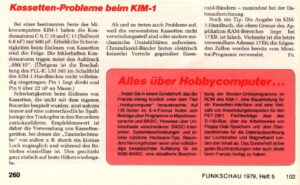
The advertisement in BYTE caught the attention of the hobbyist market. A month later, BYTE ran a feature article titled, ‘A Date with KIM’. Byte contributor Richard Simpson gushed about the low price and quality of the feature-packed KIM-1. He accurately identified it as the ideal system for anyone who did not want to assemble a kit. The KIM-1 subsequently became a favorite of BYTE and other popular homebrew publications, such as Dr. Dobbs Journal, Kilobaud, and Interface Age. Articles and projects appeared in these magazines well into 1979.

Advertisement for KIM-1 in BYTE Magazine.

MOS Technology released the KIM-1 in 1975, the same year as the Altair 8800 computer. The Altair has come to be known as the first computer system in North America to herald the new microcomputer revolution. The differences between the KIM-1 and the Altair computer illustrate a split in design philosophy within the computer world. The KIM-1 was a single-board computer, with all components mounted on a single printed-circuit board. It had room for expansion, but there were no slots to insert adapter cards. This design philosophy reduced production costs and thus gave the KIM-1 a major pricing advantage over the Altair. Commodore computers would follow this tradition of containing everything on a single board, with specialized user ports for peripherals. The Altair 8800 used an Intel 8080 chip, which retailed for $360, but Ed Roberts was able to negotiate the price down to $75 each in bulk. Still, he needed to sell his computers for $439 in kit form, and $621 assembled to make a profit. MOS Technology was able to profitably sell KIM-1 systems for $245.
Though it was not a true personal computer, MOS Technology soon discovered the KIM-1 had a large market. “That was one of the things that took MOS by surprise,” recalls Bob Yannes. “Throughout the early days of computers, one of the most successful computers introduced in that timeframe was the KIM-1.
“They had developed the KIM-1 as a sort of sales tool for the 6502 processor. They would say, ‘Here’s a development system for you, you can design your own computer system and develop your software on the KIM-1 and help understand the hardware architecture and so forth.’ And people would use them and say, ‘Why do we want to design our own computer? We have one right here and it’s only [$245], which is cheaper than we can build it for.’ They would just buy KIM-1’s and bury them in their products.”
Hobbyists began enthusiastically calling and writing for the kit. Though the goal had been to drum up interest in the 6502 chip, it soon became apparent that microcomputers would also be a valuable source of revenue for the company. According to Kilobaud magazine, MOS Technology sold over seven thousand KIM-1 computers by June 1977. At $245 each, revenue was in the millions, which helped MOS pull through a tough financial period. “They sold a lot,” says Charpentier. “By God, they sold thousands of them – ten thousand or something like that. It was a big number of processors back then.” There was an obvious demand for computers.
The appeal of the KIM-1 was not lost on Chuck Peddle. “It was a complete package, and there are a lot of people who bought it just for that reason and learned something, and then said ‘Okay, that’s all I can do.’ But we were seeing those people and talking to them and getting feedback.”

The Seeds of the Software Industry

While the early microcomputer industry focused on hardware, very few people focused on software, with the notable exception of Bill Gates. As a result, there was a conspicuous absence of quality microcomputer software. Byte magazine noted this in December 1975, describing the situation as a “software vacuum”.
But when it came to software, the KIM-1 had an advantage over other microcomputers. The single board design resulted in a homogenous population of computers, which guaranteed programs would work from one system to the next. The simple operating system put all KIM-1 users on equal footing, so programmers knew their programs would run on all standard KIM-1 computers. Distributing the programs was also easy due to the standard tape-interface. Soon, programmers began copying and distributing their code on low cost audio tapes.

MOS Technology sold one of the earliest KIM-1 software packages at a time when no one knew what might appeal to users. One obvious application was number crunching. The 6502, like all chips at the time, could not perform many mathematical functions – it could add and subtract numbers; all other operations were iterations of these two functions and had to be coded by the developer. MOS Technology developed a program called KIMATH, which effectively transformed the KIM-1 into a full-function calculator. KIMATH also added the capability to handle decimal numbers with high precision. As usual, the MOS Technology documentation included with the software was outstanding, complete with a manual and assembler source code.

Another early favorite of development was music. Since the KIM-1 did not contain a native sound device, users connected a small piezoelectric speaker to a few pins on the IO port. Other hackers found a way to play music by recording beeps to the cassette tape. Once they recorded the music, they ejected the tape and played it back in an audio cassette player.
The seventies was the age of hardware hacking (hacking is used here in its original positive sense – describing experimentation in the pure spirit of inquiry), and hardware projects proved popular among KIM-1 users. One gifted 12-year-old hacker, Tod Loofbourrow, created a 70 pound, six foot tall robot using the KIM-1. Hayden Publishing approached Loofbourrow to write a book about his robot, which he subsequently wrote on yellow-lined paper. He titled his book, How to Build a Computer Controlled Robot, and it went on to become a successful publication.3

The calculator-like KIM display would seem to be a poor candidate for playing games, but games were among the most popular programs for the KIM-1. Most game adaptations were simple pen and paper mind-challenges, which ranged from the well known (Tic-Tac-Toe, Hangman, Mastermind, Maze) to the obscure (Hunt the Wumpus, NIM, Shooting Stars).
Programmers had to design their games for the minimal KIM-1 display which meant that they often had to rely on the imagination of the player. In Maze, the player could only see the walls directly surrounding the small blinking avatar. Hunt the Wumpus required the player to use a pencil and paper for working out a strategy. With such concessions, most mind games were easily adapted.
Gambling and card games were also especially well suited to the limited display. Programmers learning their craft created Blackjack, Craps, Bandit (Slot Machines), and a horseracing game.
Surprisingly, programmers even tried action games. These primitive games went by such names as Duel, Farmer Brown, Ping-Pong, and Asteroid. Duel was notable as being one of the earliest two-player games on a microcomputer. It was a simple but fun reflex game where each player watched the display and tried to hit their button first when a character appeared.
No one attempted to sell any of this early software. Programmers shared their games, copied them to tape, and widely distributed them to whoever wanted a copy. They saw games as a way to learn about programming while creating something fun. Most of these early games lived on in more advanced computers years later.
One of the earliest KIM-1 users enjoying these primitive games was Chris Crawford. Crawford delighted in the choices these games allowed and eventually programmed his first computer game using a KIM-1. Years later, Crawford developed famous games for Atari and became influential in game design theory.

Another early programmer who would gain recognition in the industry was Jim Butterfield. For Butterfield, using a KIM-1 was an adventure in exploration. His goal was to uncover the hidden secrets of the KIM-1 and pass that knowledge on to other users. Jim has the rare ability to understand complex subjects and describe them in simple terms. One of the biggest barriers to learning about microcomputers in those days was the problem of communicating knowledge since the average hacker seemed to be speaking a different language. Butterfield allowed those on the outside to enter the world of programming in comfort.
At gatherings with other KIM-1 users in his native city of Toronto, Butterfield presented his new finds to an attentive audience seeking to unlock the mysteries of the computer. One of his most popular programs was a game. The Apollo moon missions had always been closely associated with computers and the vivid pictures were still in Jim’s mind in the mid-seventies. This inspired him to write Lunar Lander, a simulation of landing on the moon. The game started with the user at the controls of a lunar module 4500 feet above the moon’s surface, and slowly descending. Players used the number keys to control the throttle. To add a sense of urgency, there were only 500 units of fuel to expend. If a player set the throttle too high, the rocket soon used all its fuel and crashed into the surface..
Rather than try to represent the scenario graphically, Jim chose to display the altitude, fuel, and rate of decent as numbers. Anyone playing would have to imagine himself huddled in a capsule with only the instrument readings to guide him. Four glowing red LED digits displayed the altitude and the right two digits represented the rate of descent.
Lunar Lander might seem primitive by today’s standards, but back in 1975 board games were the most popular games available. Snakes and Ladders, Monopoly, and Checkers were the pinnacle of gaming, so something like Lunar Lander was futuristic by comparison. Lunar Lander was a hit at conventions and gatherings, where it fascinated hobbyists. Part of the appeal was the adventure element. Individual landings could last five minutes or more, so players could become deeply engaged in a single game. For a grueling stretch while the lander descended, a player would intently study the rate of decent versus the altitude, and occasionally glimpse the fuel gauge. After four minutes, the lander would be close to the surface, and tension began to mount. If everything went just right, the player was rewarded with a SAFE message. More often, fuel ran out and the module went crashing into the lunar surface as the dreaded DEAD message flashed onto the screen.4

Jim Butterfield also created a small utility called Hypertape, which had an impact on the KIM-1 user community. Butterfield was having lunch with a friend who also owned a KIM-1, and mentioned that the unusual circuitry of the KIM-1’s cassette tape input would make it possible to enhance the speed of tape reading. “You don’t need all those 1’s and 0’s written on the tape,” he said. The friend, Julien Dubé, asked how that could be accomplished and Jim outlined his approach. The next day, Julien reported a speedup of three times. Feeling that this was a challenge, Jim looked more closely at the code, and found extra ways to accelerate the format. The final version of the program allowed data to be written six times faster. A full one-kilobyte program now only took 20 seconds to load with the standard KIM-1 system, as opposed to the regular two minutes.

Commodore Chessmate: a 6530 computer

The Chessmate is a 6530 – KIM-1 like computer. Keyboard, LED display are used as in the KIM-1. Peter Jennings, who designed this chess computer with Commodore, build upon his Microchess 1. from the KIM-1, and used the extra ROM space to enhance it to Microchess 1.5: more chess features, a chess clock, sounds, dedicated keys, status LEDs.

The 6530-024 delivers the I/O and timer and RAM used by the Chessmate, the RRIOT ROM is not used by the main ROM. The dumped ROM of the 6530 (see below) contains no recognizable data or program,

It will not be that difficult to ‘clone’ this chess computer with the information here. A 6532 can easily take the role of the 6530. A 6502 instead of a 6504, same SRAM< a 2732 or similar ROM. The ROMs  are dumped, both for an Chessmate and a Novag Chess Champion MK I

Schematic, user manual, dumped ROMs here.