TTY DELAY routines

After RESET the baudrate is determined by measuring the length of the start bit of an incoming serial character. This means any character is usable where the first data bit is the opposite of the start bit. The KIM-1 User manual suggest RUBOUT ($7F 1111111) but ENTER ($0D 0000 1101) also works fine. SPACE ($20 0010 0000) for example does not work, any character with an odd value is OK.

0612   1C2A A9 FF               LDA   #$FF       ; COUNT START BIT
0613   1C2C 8D F3 17            STA   CNTH30     ; ZERO CNTH30
0614   1C2F A9 01               LDA   #$01       ; MASK HI ORDER BITS
0615   1C31 2C 40 17    DET1    BIT   SAD        ; TEST 
0616   1C34 D0 19               BNE   START      ; KEYBD SSW TEST
0617   1C36 30 F9               BMI   DET1       ; START BIT TEST
0618   1C38 A9 FC               LDA   #$FC
0619   1C3A 18          DET3    CLC              ; THIS LOOP COUNTS 
0620   1C3B 69 01               ADC   #$01       ; THE START BIT TIME
0621   1C3D 90 03               BCC   DET2
0622   1C3F EE F3 17            INC   CNTH30
0623   1C42 AC 40 17    DET2    LDY   SAD        ; CHECK FOR END OF START BIT 
0624   1C45 10 F3               BPL   DET3
0625   1C47 8D F2 17            STA   CNTL30
0626   1C4A A2 08               LDX   #$08
0627   1C4C 20 6A 1E            JSR   GET5       ; GET REST OF THE CHAR, 
0628   1C4F                                      ; TEST CHAR HERE

What happens here:

– bit 7 (PB7) is tested until it becomes 0 (BIT SAD and BMI DET1 loop)
– the time is counted and kept in CNTH30 and CNTL30
– bit 7 is tested for becoming 1 (LDY SAD and BPL DET3)
– the rest of the character is read in by jumping into GETCH , the actual character received is not tested.

1006   1ED4             ;		
1007   1ED4             ;       DELAY 1 BIT TIME   
1008   1ED4             ;       AS DETERMINED BY DETCPS
1009   1ED4             ;
1010   1ED4 AD F3 17    DELAY   LDA   CNTH30     ; THIS LOOP SIMULATES 
1011   1ED7 8D F4 17            STA   TIMH       ; DETCPS SECTIONS AND WILL DELAY
1012   1EDA AD F2 17            LDA   CNTL30     ; 1 BIT TIME
1013   1EDD 38          DE2     SEC   
1014   1EDE E9 01       DE4     SBC   #$01
1015   1EE0 B0 03               BCS   DE3
1016   1EE2 CE F4 17            DEC   TIMH
1017   1EE5 AC F4 17    DE3     LDY   TIMH
1018   1EE8 10 F3               BPL   DE2
1019   1EEA 60                  RTS
1020   1EEB             ;		
1021   1EEB             ;                          DELAY 1/2 BIT TIME   
1022   1EEB AD F3 17    DEHALF  LDA   CNTH30     ; DOUBLE RIGHT SHIFT OF DELAY                              
1023   1EEE 8D F4 17            STA   TIMH       ; CONSTANT FOR A DIVE 2 
1024   1EF1 AD F2 17            LDA   CNTL30
1025   1EF4 4A                  LSR   A
1026   1EF5 4E F4 17            LSR   TIMH
1027   1EF8 90 E3               BCC   DE2
1028   1EFA 09 80               ORA   #$80
1029   1EFC B0 E0               BCS   DE4

The actual delay routines use the same logic as DETCPS. IN DEHALF the delay time is divided by 2 and jumped into DELAY.

SPEED CONTROL OF KIM-1 TTY PORT
KIM User notes Vol 06

If you are having problems trying to use a high speed terminal with the KIM YTY port the following information might be useful. To start with, the Reset/ Rubout sequence activates a subroutine called DETCPS (1C2AH to IC4EH)
which determines two constants CNTL30 (17F2N1 and CNTH30 (12F3H). These are used to time the serial TTY port via subroutines DELAY (1E4DH to IEEAH) and DEHALF (1EEBH to 1EFDH). DELAY and DEHALF are called by GETCH (
1E5AH to 1E87H) which inputs one character, and OUTCH (1EA0H to 1ED3H1) which outputs one character.

CNTL30 and CNTH30 are the whole key to trimming up the TTY port speed. You can change the baudrate without going through the Reset/Rubout sequence simply by changing one or both of these constants.
The following list gives the values of CNTL30 and CNTH30 for several speeds as determined by my particular KIM-I Reset/Rubout sequence.

BAUD   110  150  300  600  1200 1800 2400 4800 9600 
CNTL30 85H  D8H  EBH  74H  38H  24H  1AH  06H  03H 
CNTH30 02H  01H  OOH  00H  00H  00H  00H  00H  00H 

Now for the interesting part. At lower speeds (110 through 1800 Baud) everything works fine with these values. But, at higher speeds problems arise.
Repeated Reset/Rubout sequences kept producing CNTL30 = 1AH for 2400 Baud. This value did work for most functions like examine and fill memory. however, for tape dump (Q command) intermittent characters were lost.
This problem was eliminated by substituting either 18H or 19H In CNTL30. All functions worked perfectly for either value.
At 4800 Baud I was unable to use the terminal at all. It acted more like it wanted to work at CNTL30 = 07H rather than at 06H, but no value between 05H and OAH would make it work.
At 9600 Baud the slow functions like examine and fill would work, but tape dump (Q) resulted in severe loss of characters.
The problem at these speeds is that the quantization level between allowed speeds (i.e. integer values of CNTL30) is so large that unless you are lucky you will not hit close enough to your terminal speed.
Since CNTL30 as used in a software timing loop to count instruction sequences (thus machine cycles) the high Baud can be fine tuned with the system clock.
You should be able to use the technique described by R. H. Burhans (page 10, issue #5. May 77, KIM-1/6502 Users Notes) to perform this fine tuning.

For casual use, 2400 Baud (or maybe even 110 Baud) is satisfactory with no hardware modifications.
However, if you have a dedicated high speed terminal you may find it worthwhile to fine tune either the KIM-1 clock or the terminal clock.
This will allow you to utilise the KIM-1 software (like GETCH and OUTCH) at high speeds. After you become accustomed to it. 9600 Baud is nice. 2400 ok, 1200 a bit of a drag. and anything less unbearable.
Finally, since CNTL30 • 03H (greater than zero) for 9600 Baud you should be able to fine tune for 19,200 Baud. and maybe (but probably not) for 38,400 Baud. Dwight D. Egbert

Jim mcClahanan notes

The PAL-1 (just like the KIM-1) uses a ‘soft UART’ or ‘bit banger’ for its serial I/O. I’m not a fan of this approach, but at the same time it demonstrates what could be accomplished with a minimial amount of hardware. The PAL-1 automatically figures out the appropriate delay between bits of the serial character when you press enter after a reboot. I have found that decreasing the value actually significantly improves the odds of an error-free load of larger punchtape format files. Below is a table for values found and suggest for $17F2.

Baud    Found   New
300     $EA     $E8
1200    $37     $35
2400    $1A     $18
4800    $0B     $0A

I haven’t tried to optimize the delay values. Right now I’m using 5 ms between characters and 500 ms between lines when doing 8K transfers and with the modified values I usually am successful. With the default values, it seemed like even with longer delays things would slip out of synchronization at some point more often than not on large transfers.

OUTCH send a character to TTY

OUTCH sends one character via the serial output vai bitbanging
8N1: All 8 databits are sent. One stopbit.

A destroyed, Y=FF, X preserved.

0979   1E9E             ;       PRINT 1 CHAR   CHAR=A
0980   1E9E             ;       X IS PRESERVED, Y RETURNED = FF
0981   1E9E             ;       OUTSP    PRINTS 1 SPACE   
0982   1E9E             ;
0983   1E9E A9 20       OUTSP   LDA   #$20       
0984   1EA0 85 FE       OUTCH   STA   CHAR
0985   1EA2 86 FD               STX   TMPX
0986   1EA4 20 D4 1E            JSR   DELAY      ; 10/11 BIT CODE SYNC
0987   1EA7 AD 42 17            LDA   SBD        ; START BIT
0988   1EAA 29 FE               AND   #$FE
0989   1EAC 8D 42 17            STA   SBD
0990   1EAF 20 D4 1E            JSR   DELAY
0991   1EB2 A2 08               LDX   #$08
0992   1EB4 AD 42 17    OUT1    LDA   SBD        ; DATA BIT
0993   1EB7 29 FE               AND   #$FE
0994   1EB9 46 FE               LSR   CHAR
0995   1EBB 69 00               ADC   #$00       
0996   1EBD 8D 42 17            STA   SBD
0997   1EC0 20 D4 1E            JSR   DELAY
0998   1EC3 CA                  DEX   
0999   1EC4 D0 EE               BNE   OUT1
1000   1EC6 AD 42 17            LDA   SBD        ; STOP BIT
1001   1EC9 09 01               ORA   #$01
1002   1ECB 8D 42 17            STA   SBD
1003   1ECE 20 D4 1E            JSR   DELAY      ; STOP BIT
1004   1ED1 A6 FD               LDX   TMPX       ; RESTORE INDEX
1005   1ED3 60                  RTS

A subroutine that sends out an 8 bit character via the serial TTY output followed by one stop bit via bitbanging to PB7. Contrary to GETCH this allow 8 bits characters.
The receiving device should be set to 8N1 (8 databits, no parity, 1 stopbit)
Timing is done with the 1 bit DELAY routine.
A is lost, Y = FF, X preserved.

What is happening here?

  • The character to send is stored at zeropage CHAR (984).
  • save X
  • A 1 bit delay, just to be sure (986)
  • set PB7 to the start bit 0 (987-989)
  • a 1 bit delay (980)
    • get current value of PB7 (LDA SBD and AND #$FE) (982)
    • shift databit into carry (LSR CHAR) (994)
    • set carry to PB7 (ADC #$00 and STA SBD) (985)
    • delay 1 bit (987)
    • repeat for 8 databits
    • (998-99)

  • set stop bit 1 (1000-1002)
  • delay 1 bit, leave PB7 in rest state (1003)
  • restore X

Serial file transfer issues

Compensate for timing
The KIM-1 character routines are quite primitive and not rebust : bit-banged, not interrupt driven, no hardware handshake so no buffering and it is CPU intensive.
When you sent characters quite fast to the KIM-1 (and that means any baud rate from 1200 to 9600, and the KIM-1 also has to do some processing like storing the record just received, it is to be expected the KIM-1 will be too late reading the next record, skip a record and sync at the next and leave the program received in chaos.
So we need to give time to the poor KIM-1.

1200 baud, 20 ms character delay, 200 ms line delay is conservative but reliable for me. It is slow ..

An example for Teraterm is shown here:

RS232/TTL to the KIM-1 20 mA interface

The 20 mA current loop TTY interface of the KIM-1 may look alien. It is not, very simple to interface.

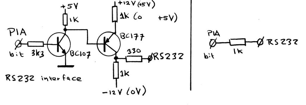
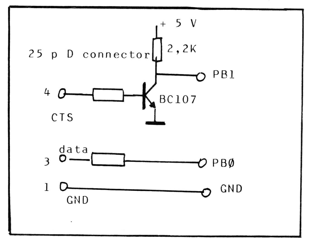
To RS-232C is requiring a negative power supply voltage (-5V – – 12V) to be reliable. Here two examples of transistor based (any general purpose transistor will work)
Using GND instead of -12V may work with some USB RS232 connectors, UGREEN types are known to work, many others are not.

My circuit, used from 1978 on. 9600 baud without issues.

From KIM Hints

A modern approach would be to use a special IC that generates the right power lines itself.

Corsham KIM-1 I/O board

TTL USB to to the KIM-1 20 mA interface
Since this is 5V only it can be simple. The output of the KIM-1 needs an inverter (a simple transistor emitter follower will do as seen in the Corsham I/O board ) , the input can be connected straight away.

Execute a program: GOEXEC

Both user interfaces of course allow to start a user program.

On the keyboard the GO key is used to start the program (line 138, via a JMP to GOEXEC)

0678   1CA4 C9 13               CMP   #$13       ; RUN
0679   1CA6 F0 31               BEQ   GOV

0711   1CD9 4C C8 1D    GOV     JMP   GOEXEC  

The TTY CLI the G command handler at line 292 calls GOEXEC.

0864   1DEF C9 47               CMP   #'G'       ; GO EXEC
0865   1DF1 F0 D5               BEQ   GOEXEC

GOEXEC itself

0072   00EF             PCL     .BLOCK  1          ; PROGRAM CNT LOW
0073   00F0             PCH     .BLOCK  1          ; PROGRAM CNT HI
0074   00F1             PREG    .BLOCK  1          ; CURRENT STATUS REG
0075   00F2             SPUSER  .BLOCK  1          ; CURRENT STACK POINTER
0076   00F3             ACC     .BLOCK  1          ; ACCUMULATOR
0077   00F4             YREG    .BLOCK  1          ; Y INDEX
0078   00F5             XREG    .BLOCK  1          ; X INDEX

0841   1DC8 A6 F2       GOEXEC  LDX   SPUSER    
0842   1DCA 9A                  TXS   
0843   1DCB A5 FB               LDA   POINTH       ; PROGRAM RUNS FROM
0844   1DCD 48                  PHA                ; OPEN CELL ADDRESS
0845   1DCE A5 FA               LDA   POINTL
0846   1DD0 48                  PHA   
0847   1DD1 A5 F1               LDA   PREG
0848   1DD3 48                  PHA   
0849   1DD4 A6 F5               LDX   XREG         ; RESTORE REGS
0850   1DD6 A4 F4               LDY   YREG
0851   1DD8 A5 F3               LDA   ACC
0852   1DDA 40                  RTI    

What is happening here?

Note that GOEXEC is essentially build for SST operation! That is why all those registers are loaded from zeropage, where they were stored by the SAVE interrupt handler.

Program counter, Stack pointer SP, Process register PS, X, Y, ACC are initialized from the zeropage locations and the RTI transfers the CPU execution.
The RTI (return from Interrupt) restores all registers from the stack, including the Program counter.
So the user program starts at the current selected address (in POINTL, POINTH).

While this way of starting a program has the advantage that the program may start with user supplied values for the CPU registers, there is no guarantee that these zeropage locations contain meaningfull values. In fact, after a RESET the contents of RAM and therefore these start values are random. That can create a malfunction program if it does not itself initialize registers.
And not all do, like Microsoft Basic: the decimal flag is not cleared via CLD. And the program crashes if by chance the CPU is in decimal mode.

So before using the G command it is good practice to clear location 00F1, the Processor Status register to clear the decimal flag and 00F2, the stack pointer to FF.
A well behaving program should initialize stack and do a CLD just to be sure.

Returning to the KIM monitor can be done with a JMP START (1C4F).

The KIM-1 explained

Quote from Jim Butterfield

Shortly after MOS Technology, Inc. developed the 6502 processor chip, they designed a single-board computer called the KIM-1 to show off the capabilities of the chip family, and to allow engineering prototyping.

Apart from the obvious things that a computer must have (CPU, RAM, I/O chips), they threw on the board just about anything that they thought someone might like to have as an interface. For example: the basic monitor program allowed a hex keypad input (hey, KIM stands for Keyboard Input Monitor) and 6-digit LED display; it had a bit-banger audio output which could be used to store programs on a cassette tape unit; it had a corresponding PLL audio input line that would read back from such a cassette tape; and it had teletype input/output facilities (again, bit-banger). Its basic RAM was 1K, supplemented by a little extra RAM in the 6530 I/O chips.

A feature of the board that many users never realized, perhaps, is that all on-board devices were selectable via external connections. What that means is that you could plug the KIM-1 board into a mother housing, which could, as desired, disconnect any or all of the peripheral circuits, I/O chips, RAM, or the ROMs containing the monitor.

The hardware and the software in the KIM-1 work closely together. The tiny program, less than 2KB in the two ROMs, together with the simple hardware is very clever designed.

The KIM-1 is a complete computer with two user interfaces and two types of data storage with a simple namespace. It is one of the first 6502 computers, and many clones or derived 6502 SBC systems are designed with more or less KIM-1 copied parts of the software and hardware. On this site you can find many examples!

On the following pages I will try to explain how all this is working together. It will not be a rewrite of the KIM-1 user manual, please read that first, but more a deeper personal dive into the software and hardware of what the makes the KIM-1 tick. Also expected a basic knowledge of the 6502, the 6530 (see the datasheets and the books) and digital electronics.

The source extracts are taken from the reconstructed source listing of the KIM-1.

The KIM-1 monitor

The KIM-1 monitor software exists of two separate parts. The 6530-002 RRIOT ROM, called KIM as separate IC, RRIOT and the 6530-003 RRIOT ROM.
The two are not written as one , the 6530-002 routines do not need the 6530-003. The 6530-003 only jumps into the KIM-1 monitor START entry point, the two routines are to be executed via the GO command.

One could speculate the 6530-002 software was developed together with the LED/keyboard display and TTY interface hardware. And when that design was done, the need for data storage for the user arose and the 6530-003 was added.

The 6530-003 only has audio tape read and write routines and uses the ports of the 6530-002 for the audio bit streams.
The 6530-002 can be used to build a standalone computer, the 6530-003 is an addon for a 6530-002 based system.
Besides sharing RAM locations in the zeropage and the RAM area in the 6530-002 RRIOT the two do not use each others routines. The 6530-003 routines only know the address of the 6530-002 START routine.

The 6530-002 ROM, the KIM monitor explained

Startup of the KIM-1: RESET

RESET is executed when the user presses the RESET button, and the 6502 RESET input is triggered.


1210   1FF7             ;       ** INTERRUPT VECTORS **
1211   1FFA             
1212   1FFA              
1213   1FFA 1C 1C       NMIENT  .WORD NMIT
1214   1FFC 22 1C       RSTENT  .WORD RST
1215   1FFE 1F 1C       IRQENT  .WORD IRQT

0606   1C22 A2 FF       RST     LDX   #$FF       ; KIM ENTRY VIA RST 
0607   1C24 9A                  TXS   
0608   1C25 86 F2               STX   SPUSER
0609   1C27 20 88 1E            JSR   INITS
0610   1C2A             ;

  .. continue with TTY/KB selection

Subroutine INITS 

0963   1E88             ;
0964   1E88             ;          INITIALIZATION FOR SIGMA   
0965   1E88             ;
0966   1E88 A2 01       INITS   LDX   #$01       ; SET KB MODE TO ADDR
0967   1E8A 86 FF               STX   MODE        
0968   1E8C             ;
0969   1E8C A2 00       INIT1   LDX   #$00        
0970   1E8E 8E 41 17            STX   PADD       ; FOR SIGMA USE SAD
0971   1E91 A2 3F               LDX   #$3F        
0972   1E93 8E 43 17            STX   PBDD       ; FOR SIGMA USE SBDD
0973   1E96 A2 07               LDX   #$07       ; ENABLE DATA IN    
0974   1E98 8E 42 17            STX   SBD        ; OUTPUT
0975   1E9B D8                  CLD
0976   1E9C 78                  SEI
0977   1E9D 60                  RTS

What is happening here?

  • After a hardware RESET (manually, the KIM-1 does not have an automated RESET circuit) the vector in the KIM-1 ROM points to $1C22 (1214)
  • Stack initialized (606-610)
  • INITS called to set hardware ports
    • MODE of LED/display set to Address (Same as pressing AD on keyboard)
    • hardware ports Port A set to input Datadirection register 0 (969 – 970)
    • Ports PIA B PB0-PB5 set to output in Data Direction $3F = 0011111 (971-972)
    • Port PB0 to PB3 set to 1, PB4 and PB5 to 0 by storing $07 = 00000111 to PIA B Data (973-974)
      This sets Row 3 output to 0, see the TTY/KB selection why

The KIM-1 explained

The hardware and the software in the KIM-1 work closely together. The tiny program, less than 2KB in the two ROMs, together with the simple hardware, is very clever designed.
The KIM-1 is a complete computer with two user interfaces and data storage with a simple namespace. It is one of the first 6502 computers, and many clones or derived 6502 SBC systems are designed with more or less KIM-1 copied parts of the software and hardware. On this site you can find many examples!

On these pages I will try to explain how all this is working together. It will not be a rewrite of the KIM-1 user manual, read that first, but more a deeper personal dive into the software and hardware of what the makes the KIM-1 tick. It also expects a basic knowledge of the 6502 and digital electronics.

Based upon my experience and study of the KIM-1 since 1979. The first years to learn the 6502 CPU and the 6530 RRIOTs. The next time when I wrote the KIM-1 Simulator (2015 to now). Many notes on paper and files everywhere. Now consolidated in a lot of pages.

Work in Progress July 6-13, 2026

KIM-1 TTY I/O, no echo, non-blocking, deaf

A page on suppressing the KIM-1 echo of TTY input, read non-blocking and make the TTY input deaf.

Problems with the KIM-1 TTY character input

  1. The KIM-1 hardware is hardware echoing incoming serial characters to the output, no echo in software involved, so you cannot influence what appears on screen. Very annoying!
  2. The KIM-1 GETCH routine is blocking, no way to check for a character coming in, like a Break. waiting.
    Also quite annoying if porting other software to the KIM-1 or you want the program interruptable.
  3. While a program is running something CPU intensive and you type something the program is not really waiting for, the characters appear on screen. Because the KIM-1 does hardware echoing of TTY input, this is unavoidable it seems

Here I present solutions for these problems in software, made possible by the genius hardware design of the KIM-1 TTY I/O.
You can have serial input wihout echo, non-blocking and even make the TTY input deaf for unwanted input.

Are they perfect? Maybe not, it is still bitbanging the incoming serial signal. It can miss the correct starting point for the incoming character bit stream.
If you want a perfect solution, you will need interrupt driven ringbuffered serial I/O with a dedicated IC like the 6850, 6511 etc.
Without this extra hardware you can achieve acceptable results with these routines.

Settings 2.3.1

Correct KIM-1 monitor source

Many sources of the KIM-1 monitor are floating around. All typed in from the user manual, most are not identical to the original text. None deliver the real KIM-1 ROMs, they fail with filling unused bytes with FF. And the text and comments are incomplete, wrong or made up.

So in June 2026 I have typed in the source of the KIM-1 monitor as it is listed in the User manual. Every line has the same line number, all text including comments is as in the paper listing. The listing is also paged as the original. Converted to a modern MOS Technology assembler format (I used TAS32), that delivers the exact ROM binary (including those 00 filler bytes!) as dumped from the real 6530-002 and -003 by me.

KIM-1 Monitor source, listing and binaries and TASM32 archive


More on the KIM-1 ROMs here.

MOStermind


MOStermind is an implementation of the Mastermind board game for the KIM-1 computer.
Developed by HKZ.

It’s written in 6502 assembly using DASM assembler and MAME as developing tools.

You can download it here

How to play

The game follows the basic rules of mastermind: the codemaster generates a hidden code and you have to guess it in a limited number of tries, while the codemaster gives you a report on how much you got right for each guess.

The codes are be composed by 4 symbols, each symbol can be one of the following 8 characters: `A`, `B`, `C`, `D`, `E`, `F`, `G`, `H`. Note that a character appearing multiple times in a code is perfectly valid.

After you type in the 4 character code and press `RETURN`, the codemaster will analyze your guess and report the result using 4 symbols:

– `O` indicates that one symbol is both the right character and at the correct spot
– `*` indicates that a symbol is a character that appears in the code, but is in the wrong place
– `.` Indicates that a character is not present at all in the code

Note that these are **NON POSITIONAL**, and they’re just shown in order of precedence: first `O`, then `*`, then `.`. They bear no information on which of the characters is right. You’ll have to find that yourself.

In case you want to cancel a guess before submitting it (to avoid wasting a try), you can press `BACKSPACE`. The guess submission will be aborted, no analysis will be performed and you’ll be able to submit a new guess.

Does it run on the KIM-1 Simulator? YES!

You only have to set the FOCAL_V3D break setting in the Settings.