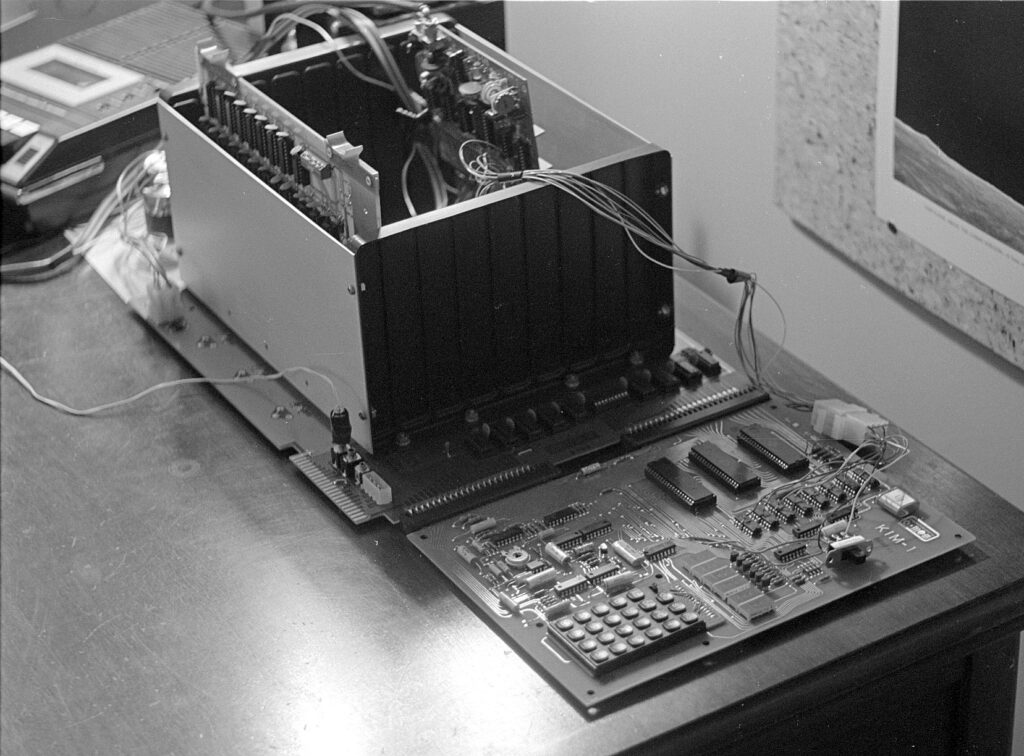
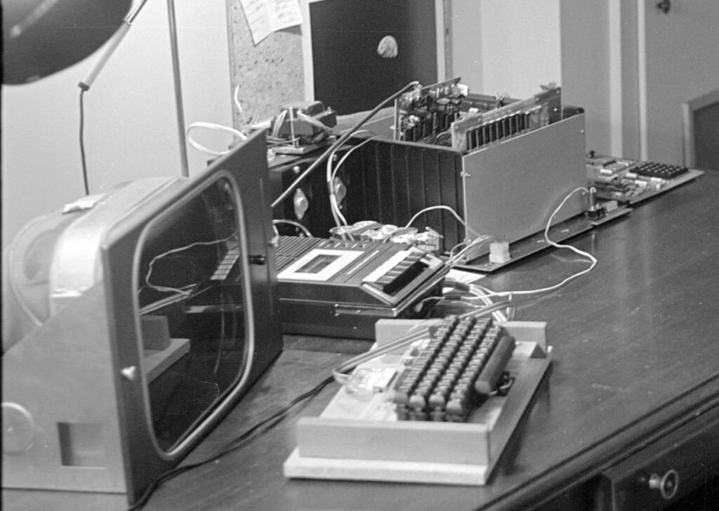
Recording programs with the KIM-1 and the cassette recorder

Original Uwe Schroeder, KIM Kenner 1, March 12 1977  Translation June 2021 Hans Otten

Introduction

A large number of KIM-1 users seem, like me, to have problems recording computer programs on the cassette recorder. For unknown reasons the KIM-1 refuses to read a program, while before it went well with the same tape. These problems have led me to study the KIM-1 system and I hope to have finally discovered the cause of the problem.
This article serves to aid other KIM-1 users to solve also these problems.

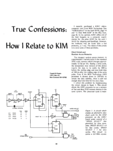
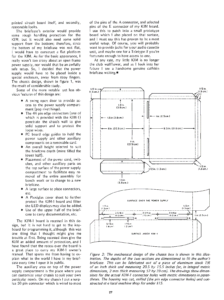
Part of the PLL circuit, including input impedances

Analysis of the KIM-1 FSK system
Signals are stored on the cassette tape with FSK (frequency Shift Keying). By consecutive high and low frequency sounds (on the KIM-1 3.6 kHz and 2.4 kHz). These high and low frequency sounds are generating not with much hardware, but with software. Reading programs is done by analyzing these sounds with the LM565 IC (a Phase Locked Loop, see User manual page 31 and fig 3.8). The fact if the sound was high or low frequency is determined after some amplification and filtering via a LM311 comparator to ‘0’ and ‘1’ and offered to I/O port PB7 of the second 6530 RRIOT).

The problems arising at the reading are probably caused by not correct functioning of the circuit around the PLL. The average cassette recorder appears to supply sometimes during a very short period a dropout to let the PLL function correctly.

Where and how things can go wrong with the PLL

  • When we record on the cassette recorder a constant tone of 3.6 kHz and listen to the recording and examine it with an oscilloscope, we see and hear the sound volume fluctuate or even disappear for short periods, we call this dropouts of the tape. These dropouts will mean a fluctuation of the sound available for the PLL to detect 10 to 100 times lower volume and cause the detection to fail. By measuring the PLL level I have seen 10 to 100% more signal than required, so that ca mean PLL malfunction.
  • If a tape is passing the head misaligned/tilted of the tape recorder head, higher frequencies are in the disadvantage and weaker. This head misalignment will cause problems with recordings from other tape recorders, bought or from other users.
  • Suppose we use a perfect +5V power supply, then VCC can be considered ‘Ground’ When we send on Audio In a AC current of 550 mV, then resistors R8 andR14 reduce the signal 1/11 of 550 Mv = 50 mV supplied to the PLL. Measurements indicate the PLL requires at least 40mV to sync the PLL and see it as a ‘high’ frequency sound.
    Remark: replace the R8 with 1K to give the PLL 250 mV instead of 50mV.
  • Suppose we use a perfect recorder with a very low output impedance. And suppose the power supply has a noise level of 600 mV. Fig 2 shows, after some calculations the noise level results in 40 mV on the PLL input. If we reduce the resistor to 1K , the noise level becomes 230 mV.

The specifications of the PLL indicate the correct functioning of the PLL at an input level of nominal 2, maximal 20 mV. The fact that the measurements indicate the PLL only operates at levels of 40 mV indicate the noise levels are at the same level as the input signal coning from the recorder. A better noise reduced may help, but other sources of interference are possible. Therefore extra amplification of the signal is preferred instead of altering the KIM-1 hardware.

Solve the tape recorder problems
Since the problems with reading of tapes on the KIM-1 seems to be related to fluctuating signal levels:

  • Record the signal as loudly as possible, use a recorder without automatic level adjustment and record so that the tape is saturated.
  • When using the loudspeaker output, experiment with the volume. But too loud means distortion and may also lead to failures.
  • Build an amplifier for frequencies 2-4 kHz 10 to 20 times, short dropouts should be well amplified.
  • Use C60 instead of C120 types. Normal cheap ferro is fine, Chrome has more dropouts.
  • If the KIM-1 reports a reading error (FFFF in the display) and you want to know how much of the tape has been read, location 17ED and 17EE contain the first address not read yet.
    Make a copy of finished programs on another cassette and check this copy for readability. Do not use this copy anymore and store it. When using a cassette often, this may lead to problems, like the mangling of the tape in the drive.

Troubleshooting
Here is a procedure to work around reading tape problems:

  1. Check if the recorder is connected to the KIM-1
  2. Check Volume and Tone control ((max high)
  3. Press Reset.
  4. Set location 17F9 to 0.
  5. Set location 00F1 to 0.
  6. Inspect location 1742. Here the information of I/O pin is shown. The display shows 1742 87
  7. Start the recorder. The middle bar of the 8 now will blink, if not : you have Error 6A (see below).
    Stop the recorder, remove the cassette and start the recorder. Now the middle bar of the 8 should not blink, else you have Error 6B (see below)
  8. If the Volume knob of your recorder controls the strength of the output signal: start the recorder and determine in which setting the blinking of the bar changes. If you have not enough headroom, see Error 7.
  9. Check of the correct detection of the high frequency.
    Type in the next program and start it (the program writes a constant tone of 3.6kHz to the recorder)
    Record this tone on the recorder for several minutes.
    Rewind the recorder and start playing. Now the display should show no middle bar 1742 07
    The bar should not blink at all, every blink indicates a dropout or such. See Error 7 and Error 8.
  10. Read User Manual C and E

Oscilloscope test
If you have an oscilloscope, do the following measurements.

  1. Attach the scope to Audio Out, e.g the negative side of C4 (user manual page B-1).
  2. If you have dual channel scope, connect the other input to the top of resistor R8, that is the PLL input.
  3. Set the timebase to 1 ms, and connect Audio-Out-High with Audio-In.
  4. Start a dump of memory with 1800G

The scope will now show figure 3.

Stop the dump program , remove the connection between Audio-In and Audio Out-High and connect the cassette recorder to the KIM-1. Start reading the tape (1873G) and move the tape to a problem area. You need to start the reading program to avoid the interference of the display. When all is right you should see the same nice picture on the scope as before.
Now increase and lower the signal level of the cassette recorder to see, if or when, there are problems with the PLL. Dropouts are visible with a image that is unstable or noise peaks. Dropouts are best studied with the 3.6 kHz recorded signal. They are visible as negative peaks on Expansion connector PLL-Test E-X. A high frequency tone is on this pin a +5V, a low as 0V.

Error 6A
The PLL is not functioning, sounds are not detected. This can be caused by:

  • No +12V power supply
  • The signal of the cassette recorder is not reaching the KIM-1
  • The signal is way too weak
  • The PLL is broken or not properly configured.
    Configuring of the PLL can be done with the program PLLCAL in Appendix I page 13
    Connect Audio-Out-High with Audio-In and start the test program on 1A6B. Inspect pin E-X PLL test on the expansion connector with a voltmeter. Adjust the variable resistor on the KIM-1 so that you see 2.5V. A small adjustment can lead to 0 to 5V, as expected.

Error 6B
The PLL is active while no input signal is present.

  • Noise signals picked up
  • Defective PLL or misconfigured of the display shows: 1742 07

Error 7
Your cassette recorder is delivering a too weak signal and you will get reading problems. See the amplifier below for a solution.
Error 8
Essential for the correct operation is the correct high frequency 3.6 kHz.

  • Dirty cassette recorder heads. Clean with a quality product
  • Unaligned head. If you are lucky there is aa small screw next to the tape head allows to adjust it, listen to a high pitch
  • Tape head is worn out, replace the cassette recorder

Amplifier between KIM-1 and the cassette recorder.

When some amplification is required the following circuit may be useful.

The amplification is controlled with variable resistor P1 from 3 to 100x. A second order Butterworth filter lowers frequencies below 2 kHz to remove mains noise.
Note the shielded cables in the drawing. Be careful to use the indicated ground point, never make a groundloop !
Place the amplifier away from noise sources and the KIM-1, noise will be amplified too!

Insert a 22 nf (22kpF in the drawing) on resistors R33 and R34 (see figure 4 right bottom and Appendix B page B1).
Adjust P2 variable resistor for Vu (output 741 opamp) = 6V
P1 controls the amplification.
The opamp (741) can be any standard general purpose audio type.
Test the amplifier as described above. Adjust for optimal volume. Record a program on tape with lower as usual volume. Try higher volume only temporarily if an error occurs.

MOS KIM-1 Reproduction documents added

Dave Williams, who designed and builds the MOS KIM-1 Reproductions, sent me three worthwhile documents:
– Schematic
– Board Layout
– Bill of Materials

You can find those on the MOS MOS KIM-1 Reproduction page.

Suppress KIM-1 echo

Original article: KIM Kenner 17 page 14, Dutch, Hans Otten. Translation 2021 Hans Otten

Problem: the KIM-1 hardware is echoing incoming serial characters to the output, no echo in software involved. Very annoying!

In the KIM Kenner 1 Siep de Vries, founder of the Dutch KIM Club mentioned how in Focal for the 6502 a trick was built in to suppress the hardware echo by manipulating the TTY out bit. I examined later how it was done, from the Focal disassembly:

34AF  E6 76       L34AF INC $76         ; random number?
34B1  2C 40 17          BIT H1740       ; check if character is incoming
34B4  30 F9             BMI H34AF       ;=> wait until startbit
34B6  AD 42 17          LDA H1742
34B9  29 FE             AND #$FE        ; clear PA7
34BB  8D 42 17          STA H1742
34BE  20 5A 1E          JSR H1E5A       ; KIM-1 input
34C1  48                PHA
34C2  AD 42 17          LDA H1742
34C5  29 FE             AND #$FE        ; isolate PA7
34C7  09 01             ORA #$01        ; set PA7 to 1
34C9  8D 42 17          STA H1742
34CC  68                PLA
34CD  18                CLC
34CE  60                RTS

Hardware echo

I took the idea and implemented the software (without knowing then in 1980 the Focal disassembly!).

The echo of incoming serial to outgoing is shown in the next figures (from the KIM user manual and the KIM Circuit poster).

The TTY KEYBD signal goes via a transistor and NAND gate U15 to PA7 port of the 6532. That signal also goes to pin 10 input  of NAND gate U26  which is the TTY out line. This is the hardware echo. When the KIM-1 sends out a character it comes from PB0 to pin 9 of of NAND gate U26 and so comes out to the TTY Out line.
Note that PB5 is connected via an inverter to NAND gate U15. The other input is TTY IN. Making PB5 high will make the TTY input PA7 deaf.
Note PB5 is also Audio out.

Suppress echo in software


The solution to suppress the echo is making output PB0 low. The NAND gate out will now stay high, ignoring any changes on the other input, which is the incoming serial character.
Only when receiving a character PBO should be made high. Also any incoming character will now not be echoed unless the program wants to receive a character!

Example program

In this routine the standard KIM-1 GETCH routine at $1E5A is encapsulated in a subroutine that prevents the echo by setting PB0. Note that this is not a complete block of the echo, it is only active when the program calls the blocking EGETCHAR. When the program sends out charactersto a dispaly, anything typed at the keyboard will also appear at the display.
The calling program is now responsible for the echoing!

0001   1000             echo .org $1000
0002   1000             ;
0003   1000             echoflag = $17E2 ; flag: 0 normal echo
0004   1000             SBD = $1742 ; KIM 6532 PIA B data register
0005   1000             GETCH = $1E5A ; KIM TTY Getch routine 
0006   1000             ;
0007   1000 AD E2 17    EGETCHAR LDA echoflag ; if notechoflag 
0008   1003 F0 08         beq normal ;  then normal echo 
0009   1005 AD 42 17      LDA SBD  ; else set TTY bit PB0 to 0 
0010   1008 29 FE         AND #$FE  
0011   100A 8D 42 17      STA SBD ; 
0012   100D 20 5A 1E    normal JSR GETCH ; get character from input
0013   1010 48            PHA ; save
0014   1011 AD 42 17      LDA SBD ; set TTY bit PB0 
0015   1014 09 01         ORA #$01 
0016   1016 8D 42 17      STA SBD 
0017   1019 68            PLA ; restore received character
0018   101A 60            RTS 
0019   101B               .end
0020   101B               tasm: Number of errors = 0

Does EGETCHAR work on the KIM-1 clones or SImulator?

Micro-KIM and PAL-1: yes, the hardware is identical, IC numbers are different
Corsham Technology: yes, though the hardware for audio is not there, there is still a NAND gate IC17C coupling PA7 and PB0.

KIM-1 Simulator V1.16 and higher: yes.

Enhanced solution: always deaf for input
If you study the hardware shown above you see PB5 also blocks the echo. The following routine tries to use this to make the input permanent deaf.

0001   1000             echo .org $1000
0002   1000             ;
0003   1000             echoflag = $17E2 ; flag: 0 normal echo
0004   1000             SBD = $1742 ; KIM 6532 PIA B data register
0005   1000             GETCH = $1E5A ; KIM TTY Getch routine 
0006   1000             ;
0007   1000             ; no echo when reading character
0008   1000             ; 
0009   1000 AD E2 17    EGETCHAR LDA echoflag ; if not echoflag 
0010   1003 F0 08         beq normal ;  then normal echo 
0011   1005 AD 42 17      LDA SBD  ; else set TTY bit PB0 to 
0012   1008 29 FE         AND #$FE 
0013   100A 8D 42 17      STA SBD ; 
0014   100D 20 5A 1E    normal JSR GETCH ; get character form input
0015   1010 48            PHA ; save
0016   1011 AD 42 17      LDA SBD ; set TTY bit PB0 
0017   1014 09 01         ORA #$01 
0018   1016 8D 42 17      STA SBD 
0019   1019 68            PLA ; restore received character
0020   101A 60            RTS 
0021   101B             ;
0022   101B             ; no echo only at wish if reading character
0023   101B             ; note that using tape I/O will leave PB5 low
0024   101B             ; 
0025   101B AD E2 17    DGETCHAR LDA echoflag ; if notechoflag 
0026   101E F0 05         beq dnormal ;  then normal echo 
0027   1020 AD 42 17      LDA SBD  ; else set TTY bit PB0 to 
0028   1023 29 FE         AND #$FE ; PB0 low
0029   1025 29 DF       dnormal AND #$DF ; PB5 low
0030   1027 8D 42 17      STA SBD ; 
0031   102A 20 5A 1E      JSR GETCH ; get character from input
0032   102D 48            PHA ; save
0033   102E AD 42 17      LDA SBD ; set TTY bit PB0 and PB5
0034   1031 09 21         ORA #$21 ; high
0035   1033 8D 42 17      STA SBD 
0036   1036 68            PLA ; restore received character
0037   1037 60            RTS 
0038   1038               .end
0039   1038               
0040   1038               tasm: Number of errors = 0

Note that using tape I/O will leave PB5 low, allowing echo, only set high when the program calls DGETCHAR.

Does DGETCHAR work on the KIM-1 clones?

Micro-KIM and PAL-1: yes, the hardware is identical, IC numbers are different
Corsham Technology: no, PB5 is not used.

KIM-1 Simulator: not yet

post

Convert to Papertape V2.2

On the Utilities page I have two programs to convert to MOS Technology papertape format: KIMpaper, a command line utility, and ConvertHexFormat, a GUI app.

All in Freepascal/Lazarus source format, and tested on Linux (Raspberry PI OS) and Windows 10 64 bit. So the programs will run everywhere Lazarus is available (MS DOS, WIndows, Linux Mac OS).

KIMPAPER  is written at the time the Micro-KIM appeared. CLI utility.  Supports Binary to/from Papertape.  Still runs fine on all platforms supported by Freepascal (Windows, MS DOS, Linux etc) after a recompilation, source available.

ConvertHexFormat is a more recent GUI utilitilty with many more 8 bit hex formats as input and output.

There were some bugs of course in older versions. V2 added the ability for multipart hex formats, records having a non-consecutive load address. That seems to wok fine since V2.1
In 2.2 a bug in MOS Papertape format for bigger files is fixed, the end-of-file record (record type 00, total line count) had a bug in the checksum calculation. KIMPAPER is and was correct in the calculation.
But in ConvertHexFormat it was wrong (as it still  is in the well known srec utility in the Unix world!).

post

PC utilities updated

The PC utilities page has seen an update of th4 Conversion hex formats utility.

Programs to manipulate the binary and hex formatted files of interest for SBC owners. Intel hex, MOS papertape, Motorola S-record, binary, hex conversion fort eh 8 bit world.
Runs on Windows, Linux, Mac due to Lazarus and Freepascal. Source included.

post

Load papertape format

The KIM-1 has two methods of loading programs:
– from audio files on the audio interface
– from papertape from a papertape reader connected to the teletype terminal

(Photos by Dave Wiliams with the MOS KIM-1 Reproduction)

The papertape method is the preferred way available for KIM-1 clone owners, since audio input input hardware is either not present or quite inconvenient and using terminal emulators is already the way we use these computers.

Now papertape format is a special MOS Technology format, already used in the TIM-1. See the KIM-1 user manual for a technical description.
This is for example the papertape output captured with the KIM-1 S command for the memory test program in the Fist Book of KIM

;1800000000A900A885FA8570A2028672A50085FBA601A57049FF850B27
;1800187191FAC8D0FBE6FBE4FBB0F5A672A50085FBA570CA1004A20FF6
;1800300291FAC8D0F6E6FBA501C5FBB0ECA50085FBA672A571CA100F73
;18004804A202A570D1FAD015C8D0F0E6FBA501C5FBB0E8C67210AD0F29
;0B0060A57049FF30A184FA4C4F1C05CE
;0000050005

Load address, data and checksums are in the records.

What the dump above does not show that the KIM-1 inserts in front of every record a series of NULL characters (a character with value 0), to give the papertape device time to do its mechnica work and also helps the slow KIM-1 load routine to do its work after a line end of a record.

A part of a real dump:

Papertape format is therefore a readable text file, but when captured from a KIM-1 output contains NULL characters.

So if we could send the papertape formatted test file to the KIM, we can load programs.

This requires solutions for the following:

Make a papertape file
The PC utilities section has programs to produce MOS papertape from binaries or other common 8 bit hex formats produced by assembler such as Intel hex, Motorola S-Record

Send a text file
Many terminal emulators that have support for serial allow to capture the serial output to a text file or send a text file to the serial input.
Good examples are nowadays Teraterm for Windows or Minicom for Linux.

Compensate for timing
The KIM-1 character routines are quite primitive and not rebust : bit-banged, not interrupt driven, no hardware ,handshake so no buffering and it is CPU intensive.
When you sent characters quite fast to the KIM-1 (and that means any baud rate from 1200 to 9600, and the KIM-1 also has to do some processing like processsing the record just received, it is to be expected the KIM-1 will be too late reading the next record, skip a record and sync at the next and leave the program received in chaso.
So we need to give time to the poor KIM-1.
1200 baud, 20 ms character delay, 200 ms line delay is conservative but reliable for me. It is slow ..

An example for Teraterm is shown here:

Decimal mode
The 6502 NMOS version is in unknown state after reset regarding decimal mode.
Most programs start with the CLD D8 instruction, but not all. Microsoft KIM-1 Basic v1.1 is one of those.

A section from the KIM Hints:

A number of KIM-1 customers have reported difficulty in achieving correct results for the sample problem shown in Sec. 2.4 of the KIM-1 User Manual. In addition, some customers have experienced problems in recording or playback of audio cassettes. (Sec. 2.5 of the KIM-1 User Manual). In all cases, the problems have been traced to a single cause: the inadvertent setting of the DECIMAL MODE.

The 6502 Microprocessor Array used in the KIM-1 system is capable of operating in either binary or decimal arithmetic mode. The programmer must be certain that the mode is selected correctly for the program to be executed. Since the system may be in either mode after initial power-on, a specific action is required to insure the selection of the correct mode. Specifically, the results predicted for the sample problem (Sec. 2.4) are based on the assumption that the system is operating in the binary arithmetic mode. To insure that this is the case, insert the following key sequence prior to the key operations shown at the bottom of Page 11 of the KIM-1 User Manual.

[AD]
[0] [0] [F] [1]
[DA] [0] [0]

This sequence resets the decimal mode flag in the Status Register prior to the execution of the sample program.

The same key sequence may be inserted prior to the key operations shown on pages 14 and 15 for audio cassette recording and playback. These operations will not be performed correctly if the decimal mode is in effect.

In general, whenever a program is to be executed in response to the [GO] key, the programmer should insure that the correct arithmetic mode has been set in the status register (00F1) prior to program execution.

Microsoft Basic 6502

Written in 1976, Microsoft BASIC for the 8 bit MOS 6502 has been available for virtually every 6502-based computer. Also for the SBC’s on this site: KIM-1, SYM-1, AIM 65 and as a port of Applesoft on the Apple 1.

Binary versions and manuals are on the pages dedicated to these machines:

Sources of early Microsoft Basic on 6502 are available on pagetable blog by Michael Steil

Build binaries from source on a Linux system (Raspberry PI OS)

First install CC65 package, the assembler and linker are required.

You need the CC65 package, a C and Macro assembler and linker for the 6502.

https://github.com/cc65/wiki/wiki is broken, https://cc65.github.io/getting-started.html is fine.

git clone https://github.com/cc65/cc65.git
cd cc65
make
sudo make avail

Now get the MS Basic source and assemble the binaries

https://github.com/mist64/msbasic
git clone https://github.com/mist64/msbasic
cd msbasic
./make.sh
cd tmp
ls

and you will see a directory of binaries (.bin), symbol table (.lbl) and object files (.o)

Compare the binary files with the binary files in the msbasic/orig folder and you will see hopefullyy they are identical!

It is not only nice to see the source, now you are able to customize a Microsoft Basic to your likings.

Steps as advised in the pagetable description:
1. Create a .cfg file by copying an existing one.
2. Adapt the make file for the new target.
3. Change the platform specific source files

and assemble again.

For example, the KB9 Basic can be changed:

  • Character in//out to a serial device
  • Control-C handler update
  • Remove the ROR workaround
  • Save/load to another storage device
  • See the KIM Kenner articles for patches on KB9 Basic

An example is this post by Gordon Henderson who made a serial interfaced Commodore Basic by creating a new variant and tweaking some conditionals, replacing the screen editor with the line editing interface of older versions.

KB-9 stands for Microsoft Basic V1.1 for the KIM-1  with 9 digits precision. .
Scanned manual
The original KIM-1 KB9 Microsoft Basic V1.1, audio wave, binary and papertape format

Solid State Tape Device for the (micro)KIM


Willem Aandewiel designed a tape device for the (micro)KIM. With a Wemos D1, ES8266 and ATTiny and some clever software to make the KIM believe a audio cassette recorder is connected.
All details here on Willem’s website.


The device in action:
https://youtu.be/R_zD5T_khKs

Willem has now published the next generation, together with a 32K RAM card, of this device.

post

Cassette interface for Micro-KIM

or KIM Clone!

By Timothy Alicie

Demonstrates his  design for a cassette interface for the Micro-KIM single board computer from Briel Computers (a replica of the 1970’s KIM-1 SBC). The original KIM-1 has a built-in cassette interface, but the Micro-KIM replica does not, so I designed and built his own. The design uses a single PIC micro-controller, is very reliable, supports all HyperTAPE speeds, and has the ability to save and play back recorded data into the KIM-1.
post

Home-Brew Cassette Interface for Micro-KIM

Design by Timothy Alicie

Demonstrates his design for a cassette interface for the Micro-KIM single board computer from Briel Computers (a replica of the 1970’s KIM-1 SBC). The original KIM-1 has a built-in cassette interface, but the Micro-KIM replica does not, so I designed and built my own.
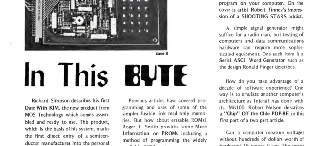
The design uses a single PIC micro-controller, is very reliable, supports all HyperTAPE speeds, and has the ability to save and play back recorded data into the KIM-1.


From the source of the microcontroller:

All design files (PCB gerbers, source and hex files PIC microcontroller) in this archive.

/*******************************************************************************
* Micro-KIM Cassette Interface, PIC16F6/27A/28A/48A Implementation
*
* The original KIM-1 uses a PLL and a comparator to implement the receive
* path of the cassette interface. These two parts have been replaced by
* this implementation which runs on a PIC microcontroller.
*
* The KIM-1 cassette format encodes each bit using two tones:
* 1) A high-frequency tone of 3623.188 Hz (1.5X the low-frequency tone)
* 2) A low-frequency tone of 2415.459 Hz
*
* Each bit is broken up into three periods, each of which is 2.484 ms long,
* during which either the low frequency or the high frequency tone is played.
*
* The high frequency tone is always played in the first time period, and the
* low-frequency tone is always played in the last time period. A bit is encoded
* as logic ‘1’ by playing the low-frequency tone in the middle time period, and
* a logic ‘0’ by playing the high-frequency tone in the middle time period:
*
* Logic 1: encoded as HiFreq-LoFreq-LoFreq
* Logic 0: encoded as HiFreq-HiFreq-LoFreq
*
* The KIM-1 cassette interface uses a PLL tuned to distinguish between the
* high and low frequency tone. The output of this PLL is then fed into a
* comparator to generate a logic ‘1’ whenever the high frequency is detected,
* and a logic ‘0’ whenever the low frequency is detected. This logic signal
* is analyzed by the KIM-1 to reconstruct the bit-stream stored on the cassette
* tape. Each bit begins with a low-high transition, and the bit value can be
* determine by the timing of the falling edge generated by the high-frequency
* to low-frequency transition within each bit.
*
* The job of the PIC KIM cassette interface implementation is to perform the
* same function of the original PLL and comparator: analyze the input signal,
* and generate a logic ‘1’ output whenever the high frequency is detected, and
* a logic ‘0’ output whenever the low frequency is detected. The implementation
* is rather simple: analyze the timings of zero-crossings detected in the input
* signal, use this information to determine the frequency of the input signal,
* and generate the output signal based on if the input signal is closer to the
* high frequency, or closer to the low frequency.
*
* The original KIM-1 tape algorithm uses a bit period of 7.452 ms, which is
* three periods of 2.484 ms each. Within each sub-period, exactly 9 cycles of
* the high frequency tone can be played, or exactly 6 cycles of the low
* frequency tone can be played.
*
* Jim Butterfield popularize an alternative called HYPERTAPE, which reduces
* these periods to speed up the data by a factor of 2X, 3X, or 6X. The only
* difference between the HYPERTAPE implementation and the original implementation
* is that the sub-bit periods are reduced. The 2X and 6X sub-bit periods are
* reduced such that a non-integer number of cycles of the high and low frequency
* tones are played within each sub-period. Thus, the PIC detects the frequency
* based on half-cycles to fully-support HYPERTAPE.
*
* Interesting facts:
*
* Original KIM-1 cassette bit-rate: 134.2 bits/sec (402.6 baud, 3 symbols/bit)
* HYPERTAPE 6X bit-rate: 805.2 bits/sec (2415.5 baud, 3 symbols/bit)
*
* Each data byte is represented as two ASCII hex digits, so the effective data
* transfer rate is 8.4 bytes/sec for the original speed, or 50.3 bytes/sec for
* HyperTAPE x6.
*
* High frequency tone: 3623.188 Hz, or 0.276 ms/cycle
* Low frequency tone: 2415.459 Hz, or 0.414 ms/cycle
* Center frequency: 2898.551 Hz, or 0.345 ms/cycle
*
* Frequency detection based on half-wave zero-crossings:
* High frequency tone: zero-crossing every 138 us
* Low frequency tone: zero-crossing every 207 us
*
* Separation between high-frequency and low-frequency zero-crossing: 69 us
* Threshold between high and low-frequency zero crossing: 172.5 us
*
* Implementation Notes:
*
* The bi-color LED lights red when an input signal is present, but it does
* not contain the correct frequencies to be a valid KIM-1 bit stream, for
* example, voice input. The bi-color LED lights green if the input signal
* contains the correct frequencies to be a valid KIM-1 bit stream. While
* receiving data, the green LED should be lit solid to ensure reliable data.

* Comparator 1 (CMP1) is used to detect signal zero-crossings by adding a bias
* to the input AC signal of Vcc/2. The bias is used as the V- comparator input.
*
* RB4 is used to monitor the PB7 line to/from the KIM-1. In audio-output mode,
* (dumping to a tape), the KIM-1 drives this line, so we can use it to detect
* audio-output mode and light the LED when the KIM-1 is dumping data.
*
* Timer 0 (TMR0) is used to light the LED indicators for a certain time period.
*
* Timer 1 (TMR1) is set up to count at 1.0 MHz, and it is used to precisely
* measure the time between zero crossings.
*
* Copyright Timothy Alicie, 2017, Timothy Alicie
*******************************************************************************/