COMAL is an interpreted structured language. A version for the KIM-1, Junior and DIS65 is available, distributed by the KIM Gebruikers Club Nederland as KGN COMAL in the 80ties.
KIM-1 version March 2025 by Hans Otten.
KGN COMAL V1 for the KIM-1 and clones, Elektor Junior and DOS65.
A product distributed and adapted to the Junior by the KIM Gebruikers Club The Netherlands in 1985-1987.
KGN COMAL V1.0 is for the enhanced Elektor Junior.
KGN COMAL V2.1 is for the DOS65 system.
In 2015 I saved KGN COMAL 1.0 and 2.1 binaries from Junior tapes and DOS65 disks.
With DOS65 came a very compact COMAL user manual.
In the Club Magazine KIM Kenner a Amazing Maze program is found.
Based upon these binaries and documents KGN COMAL is adapted to the KIM-1.
In this archive:
– KGN COMAL V2.1 DOS65
– binary as DOS65 program
– binary stripped, DOS65 preamble removed, binary only
– KGN COMAL
– Junior binary (load at 2000, start at 3000)
– comal junior dis.txt A partial disassembled and commented source of KGN COMAL Junior
– KGN COMAL KIM-1
– papertape of KGN COMAL KIM-1 (loads at 2000, start at 3000)
– binary of KGN COMAL KIM-1 (loads at 2000, start at 3000)
– User manual
– KGN COMAL User Manual
New, written in March 2025. Based upon the Dutch COMAL manual and observation made with the COMAL interpreter.
Word and PDF versions
– scans of the original material
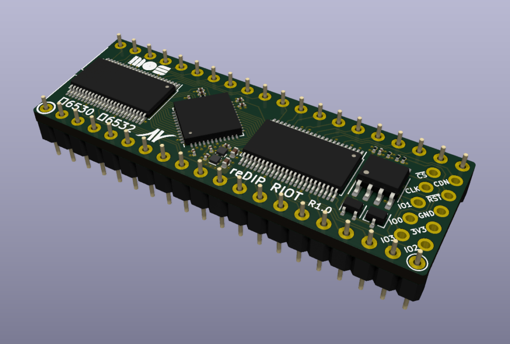
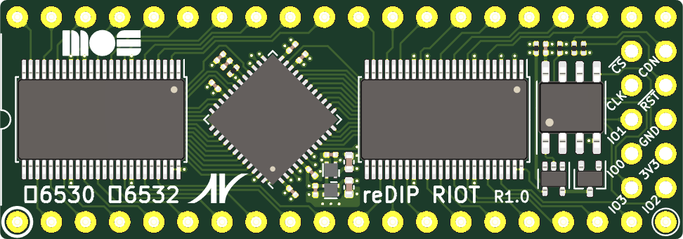
Since the 6532 is in fact a subset of the 6530 (no ROM, more RAM), it seems not too difficult to make a 6532 replacement this way.
The reDIP RIOT is an open source FPGA board which combines the following in a DIP-40 size package:
Lattice iCE40UP5K FPGA
1Mbit FLASH
5V tolerant I/O
The reDIP RIOT provides an open source hardware platform for 6530 RRIOT / MOS 6532 RIOT replacements.
4 february 2025 2025 I have built the PAl-2 kit, now designing and building a I/O card.
This information is based upon the available documentation: User manual, Schematic, BOM.
The PAL-2 is for sale by Liu Ganning at Tindie
Just followed the interactive BOM, passive components first, ICs last.
Nothing special to note, compare yours with the photo on the PAL-2 Tindie site.
Orientation of IC sockets and IC’s, check twice!
Check your soldering joints, not too much sodler, but covered with the right color solder.
And the three slider switches,: the SST keyboard one has a higher slider that the other two!
Please be careful with the Dupont power cables, double check the polarity! If in error: magic smoke!
I do not like the Dupont wires for power, serial, TTY switch. Too easy to make a mistake in the power connection.
I am now designing and building a simple I/O card for the Application connector, experimenters print, point to point wires, male pin connector to PAL-2, on board female connector for USB to Serial, power switch, TTY/Keypad switch.
That may grow later to SD or 1541 or Corsham SD card interfaces.
Video of PAl-2 #4, by Nils, running!
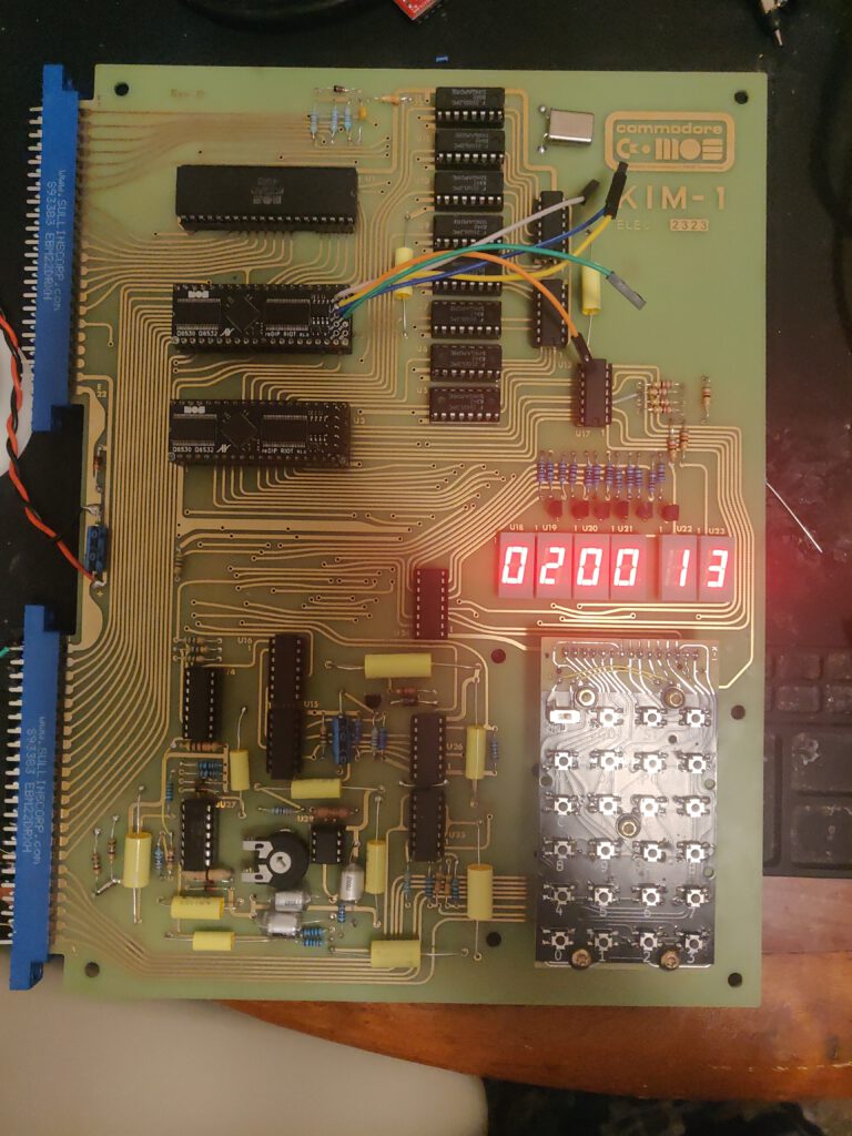
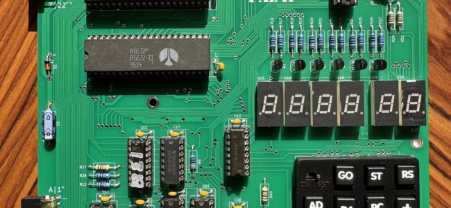
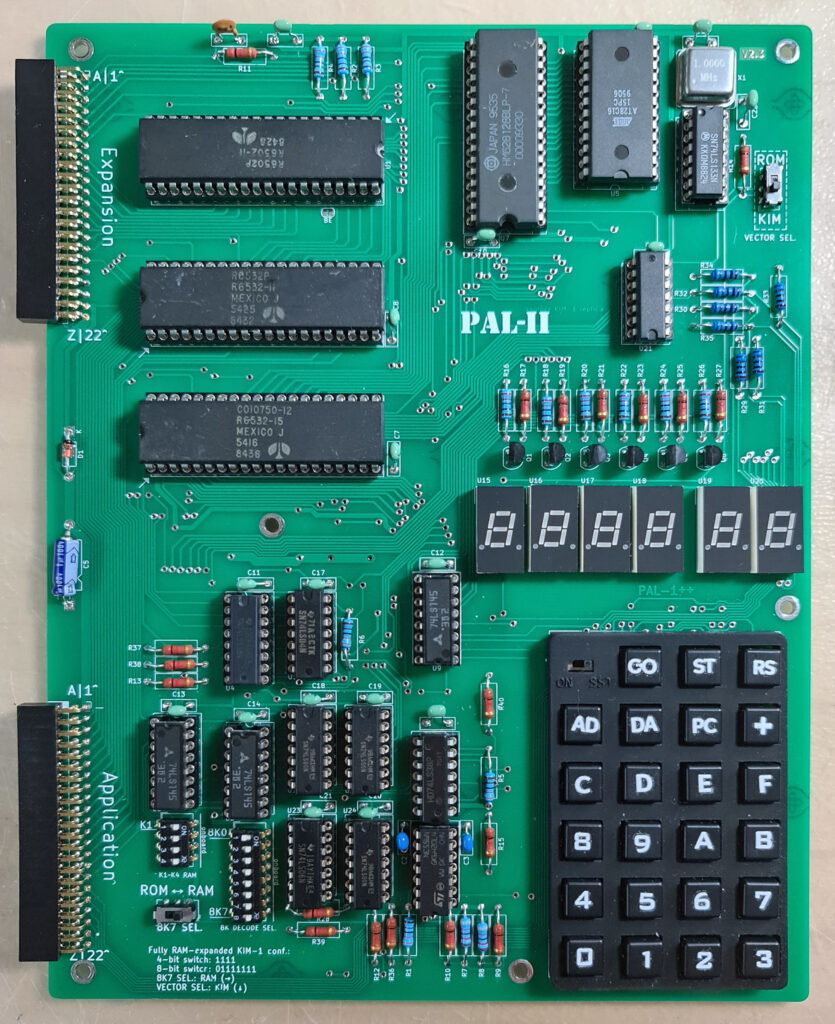
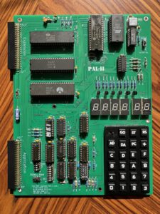
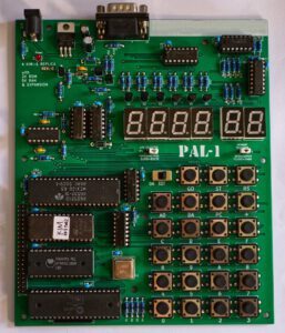
What is a PAL-2?
The PAL-2 is a kit for an SBC in the now large family of KIM-1 clones. Ranging from the Micro-KIM to the PCB exact replica by Eduardo Casino, all share the KIM-1 ROMs, LED display and TTY interface and the 6532 RIOT instead of the 6530 RRIOT.
What makes the PAL-2 unique:
It is a real and complete KIM-1 clone.
Available as a DIY kit with high quality components.
The layout is close to the KIM-1.
The good looking keypad is very close to the KIM-1
Application and Expansion connector with all relevant KIM-1 signals.
Lots of RAM in many configurable options.
Both RRIOTS 6532 on board.
TTY interface on TTL level, USB to TTL adapter included in the kit, quality serial!
Power can come from the USB to TTL adapter or from external 5V supply (same as for the KIM-1)
The PAL-2 differs from a KIM-1
No Audio cassette interface for file I/O circuit, but see below for a solution
Application and Expansion connector as 22×2 pinheader instead of PCB edge connectors
The signals on the Application connector are not all identical: no audio, TTY instead of 20 mA loop, decoding lines added
Not the same size PCB
The PAL-2 differs from the PAL-1:
The many quality improvements and enhancements make the base PAL-2 kit more expensive then a base PAL-1 kit.
If you expand the PAL-1 to the level of a PAL-2 you need to spend money on a motherboard, a RAM 32K, a second RRIOT kit, an RS232 cable and gender changer and a 9V power supply.
Improved keypad, with labels and look of the KIM-1
No need for a Motherboard
No external RAM module required
No external RRIOT required
E000-FFFF can be used freely from ROM expansion
The vectors (Reset, NMI, IRQ) can be placed in external ROM.
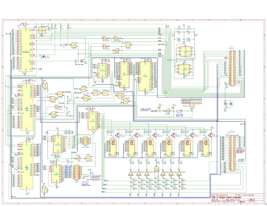
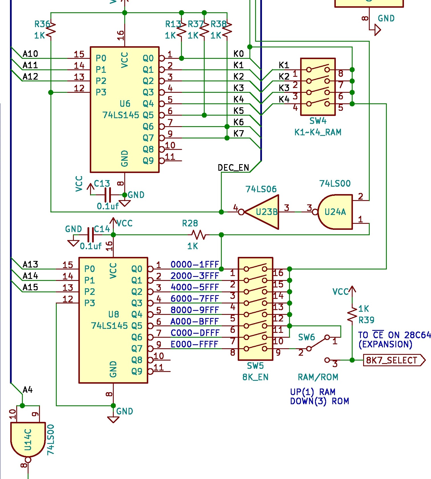
RAM decoding
The PAL-2 has a very flexible RAM memory layout, as shown in the next parts of the schematics:
Internal ROM and external ROM
The PAL-2 has a 2K ROM with the KIM-1 monitor. Since there is no audio in and out circuitry, the ROM from 1800-1BFF could be used for other programs, like the KIM Clone by Corsham Technology (Which also did not have the audio circuitry). The 28C16 is easy to program.
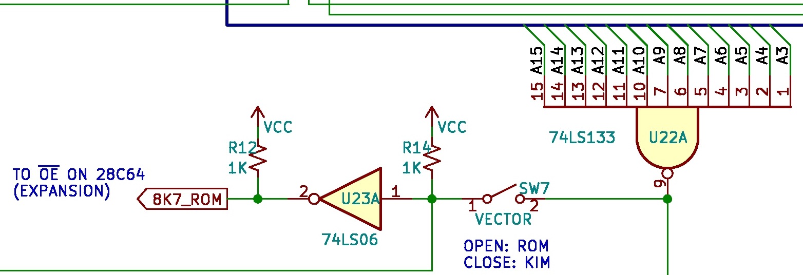
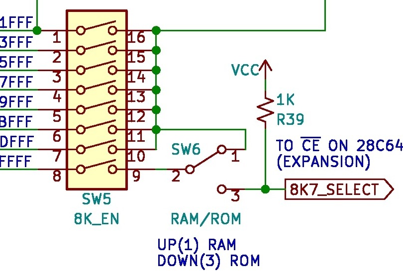
One of the first expansions that is to be expected is an external 8K ROM. The decoding for this ROM, e.g. an 28C64 is already present on the connectors and in the decoding circuit.
The decoding signals are 8K7_SELECT (CE on 28C64) and 8K7_ROM (OE on 28C64). Just the 28C64 IC has to be connected to address and data lines.
DIP Switches
The PAL-2 has a full 64K address decoder onboard, while the KIM-1 has only a 5K onboard address decoder for expansion. These two DIP switches on the PAL-2 are designed both to expand the KIM-1’s RAM and to maintain compatibility with its basic configuration.
On the PAL-2, the 4-bit DIP switch enables the onboard K1 to K4 RAM spaces, with each bit controlling 1K of memory. The K1 to K4 naming follows the definitions in the KIM-1 user manual, covering the address range from $0400 to $13FF. If all four DIP switches are set to ON, the entire 5K RAM space becomes available to the system.
The 8-bit DIP switch controls the “big segment decoder,” with each bit corresponding to an 8K memory block. These blocks range from 8K0 to 8K7, with 8K0 ($0000 to $1FFF) being the KIM-1’s default occupied address space. Since the PAL-2 is a KIM-1 replica, if you want to use it as a KIM-1 system, 8K0 must be set to OFF to allow the onboard KIM-1 logic to function. However, if you’re building a completely new system on the PAL-2, you can set 8K0 to ON to bypass the KIM-1’s onboard logic for the lowest 8K of memory.
The 8K1 block starts at $2000, controlling an 8K space beyond this address, and so on. If a bit is set to ON, the KIM-1 system will be able to access the corresponding address space, which will function as RAM. If a bit is set to OFF, the KIM-1 system will still work, but with reduced available address space. When performing expansion or add-on modifications on the PAL-2, you may need to disable certain address spaces to prevent the onboard logic from accessing the RAM chip.
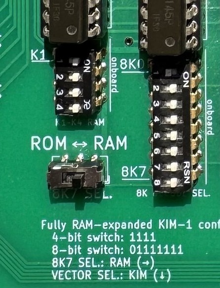
The 8K7 block, representing the highest 8K memory segment, offers additional flexibility on the PAL-2. If 8K7 is set to ON, you can choose how to use this space—either as RAM or ROM—by adjusting the 8K7 SEL switch. For example, if you write a program (such as a tiny OS for the KIM-1) and burn it onto a ROM chip—similar to the well-known Jim’s ROM (but smaller)—you can connect the ROM to the PAL-2 (with some additional hardware, which is still under development). To boot from your ROM chip, use the VECTOR SEL switch to select ROM, allowing the system to retrieve the top three vectors from the ROM chip instead of the onboard KIM-1 ROM.
Application and Expansion connectors
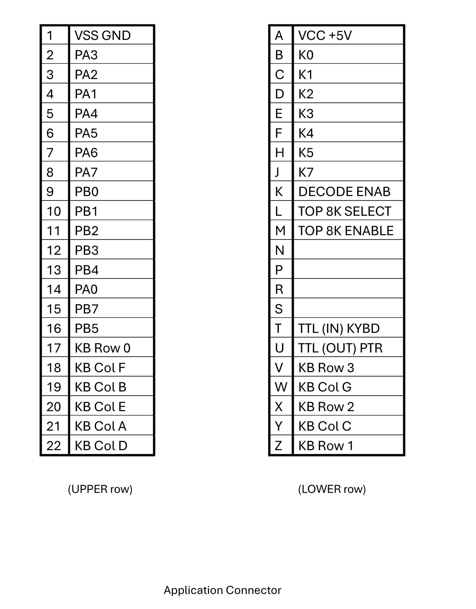
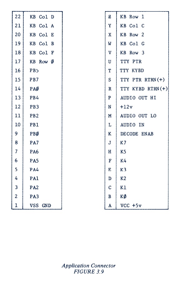
KIM-1 Application connector
Differences on the Application connector with the KIM-1:
AUDIO IN -> 8k7_SELECT
AUDIO OUT LO -> 8K7-ROM
TTY in and out now at TTL level for USB to TTL converter
TTY PTR and KYBD, +1wV, AUDIO OUT LO not connected
This means, even if the edge to pin connector issue is solved, the standard KIM-1 I/O boards will not work for TTY and audio.
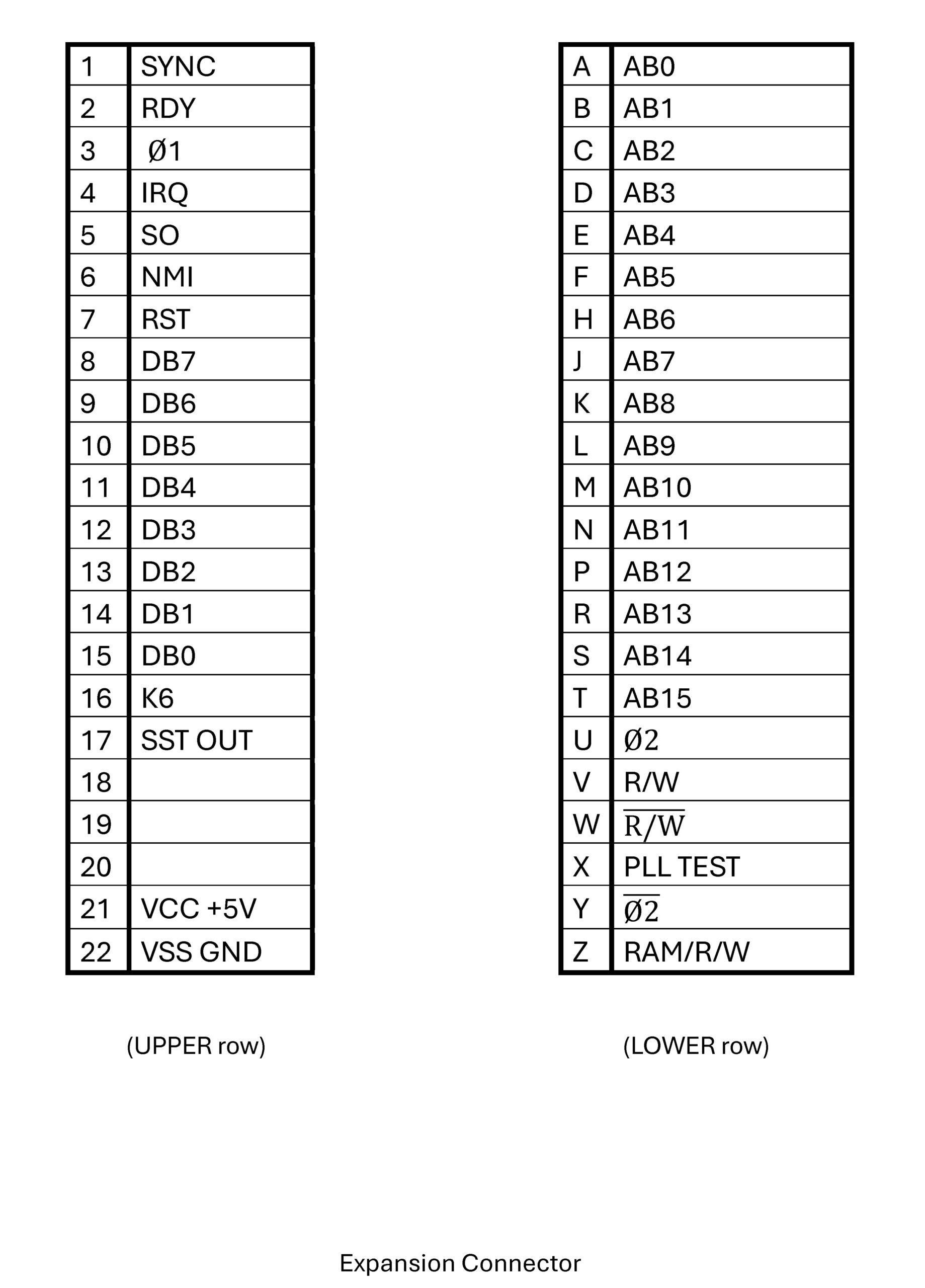
The expansion connector is identical to the KIM-1.
KIM-1 Expansion connector
Power supply
Power has to be applied in the standard KIM-1 manner to the application connector Pin 1 = GND, pin A = 5V. Note that reversing these pins will mean the dead of the PAL-2!
Expansion
As a first suggestion for a PAL-2 extension I see a board connected to Application and Extension connectors with:
Power switch
28C64 (or bigger, switchable in 8K chunks) EEPROM
Connector for the USB to TTL
External power connector, switchable between this and USB to TTL connector
TTY/LED keyboard switch
connector for the Application I/O ports PA0-PB7
Power switch
Optional:
Pin connector for PAL-1 Cassette Interface audio board
The KIM-1 has hardware and software in the 6530-003 ROM to save and dump files on audio tape.
Not used by most KIM clone users, so it is not present on the Corsham KIM Clone and the PAL-2.
But it is possible to have the audio in/out with one patch wire between pin 11 of U12D and the application connector!
KIM-1 Audio and TTY circuit
PAL-2 Audio and TTY circuit
On the KIM-1 circuit you can see the audio I/O is seen by the CPU at pin PB7 of the 6530-003. It is either an input or an output under control of the audio routines in the ROM.
The U26 (also present on the PAL-2 as U12d) is an open collector NAND feding PB7. On one input of U26 is PB5 from the 6530/32 (inverted by U16 (KIM-1_ or U10D (PAL-2), on the other is the output of the audio circuit generating TTL pulses from the audio sound input. This way PB7can be used both as input and output.
The PAL-2 and the KIM-1 has on the extension connector the signal PLL(_TEST), which is connected to U126/U12D. This is on the KIM-1 the output of the audio circuit.
So we have audio in (at TTL level) on the PAL-2 covered!
Audio out is available at PB7 at TTL level. With a patch wire between PB7 (or pin 11 of the U12D) to the application connector.
With the PAL-1 Cassette interface we can have the PAL-2 read and write KIM-1 audio cassette files this way. PLL_TEST to TAPE and a wire from PB7 to PB7 is all you need to connect to the Cassette Interface (and GND and +5V ofcourse).
Leaving R9 out of the Cassette Interface may be a good idea, there is already a pullup in the PAL-2 of 1K.
Physical Dimensions
The connector on the PAL-2 is a 2.54 mm pitch 2×22 female pin header connector.
The dimensions of the PAL-2 PCB are 168 mm x 218 mm.
Next two images show the connector, first shows the distance between the two connectors, while the second shows the distance from the PCB edge to the connector’s outer side.
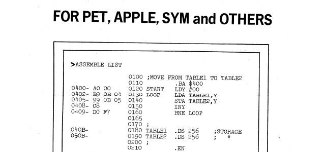
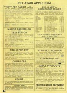
MAE (Macro Assembler Text Editor) or ASSM/TED is a program sold by Eastern House Software for the KIM-1, Apple, PET, C64 and more 6502 based machines.
RAE was the name by Synertek for MAE, as ROMs for the SYM-1 which could be installed to add the Resident Assembler/Editor (RAE). Synertek contracted Eastern House Software to port their Macro Assembler/Editor (MAE) into an 8 KB ROM. AS you can see in the reconstructed source, the adaptations were not much more than adding the SYM-1 I/O such as character I/O and tape handling, the essence of MAE stayed as RAE. It was not that popular in the SYM-1 world, even Synertek used internally another assembler, with more MOS Technology compatible syntax.
The author of MAE and RAE, was Carl Moser. MAE was sold in various forms not only for the KIM-1 and SYM-1 but also for other 6502-based computers including Commodore, Atari, KIM, and Apple and in the Netherlands the Elektor Junior. Other forms of MAE included a cross assembler for 6800 and 8085.
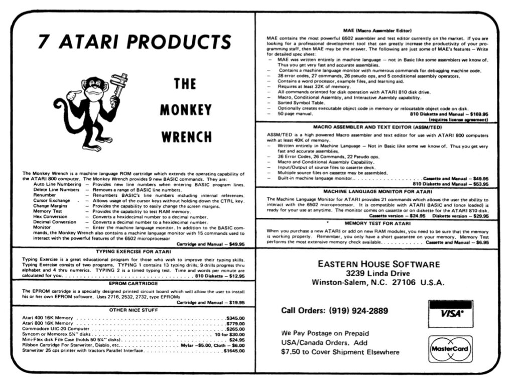
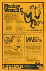
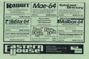
Carl Moser and JR Hall were founders of Eastern House Software, the company that created several products for Atari 8-bit users, including Monkey Wrench and Monkey Wrench II, and the KISS word processor.
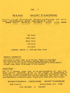
On topic on this site are the preserved KIM-1, SYM-1 and Elektor Junior versions. I have binaries, manuals and (reconstructed) sources for these versions for download.
Note that the manuals for the SYM-1 RAE are well written, and a good addition for the manuals of MAE.
To get text into and out of the ASSM/TED program on the 6502 computer to the PC world,one can use several methods.
Written in Freepascal. Sources included, can be compiled in Linux etc.
The first method is using a terminal emulator and upload a text file or catch the output of the ASSM/TED program.
That gives some problems, mostly related to missing line numbers, or too much blanks.
Strip Blanks
The output of ASS/TED to the screen contains many blanks. When you want to uplaod the captured output, those blanks have to go
D:\myfiles\MAE\PC tools>StripblanksMoser.exe
V1.0 Strip blanks from captured ASSM/TED Moser source file
V1.0 Hans Otten, 2024
Syntax: StripBlanksMoser <sourcefile with blanks> <output source file to upload
to ASSM/TED> [Y]
Y to overwrite outputfile without question asked
Add numbers
When you have a MAE/RAE source file without numbers, you can add those with this utility, increment of 10.
D:\myfiles\MAE\PC tools>AddNumbersMoser.exe
V1.0 Add numbers 0001-9999 to source file to make a ASSM/TED Moser source file
V1.0 Hans Otten, 2024
Add numbers 0001-9999 to ASSM/TED Moser source
AddnumersMoser <sourcefile without numbers> <output source file with numbers> [Y]
Y to overwrite outputfile without question asked
The other method is to dump or upload the text buffer as memory binary dumps.
Text is stored in memory as: ..
e.g.
the text
10 test
is stored as:
00 10 20 74 65 73 F3
RAE to TXT
Converts a binary MAE/RAE file to an ASCII text file without line numbers and normal line end
D:\myfiles\MAE\PC tools>RAEtoTXT.exe
V1.0 Convert a  ASSM/TED Moser RAE memory dump to text file
V1.0 Hans Otten, 2024
RAEtoTXT sourcefile memorydump output text file  [Y]
Y to overwrite outputfile without question asked
TXT to RAE
Converts a text file to binary RAE format, with line numbers.
D:\myfiles\MAE\PC tools>TXTtoRAE.exe
V1.0 Convert a  text file to ASSM/TED Moser RAE memory dump
V1.0 Hans Otten, 2024
TXTtoRAE <textfile > <output memorydump file  [Y]
Y to overwrite outputfile without question asked
How to dump or upload the the MAE/RAE text buffer
Dump
Start ASS/TED and add some lines
C 1979 BY C. MOSER


4163-53FC  5400-5EFC  5F00
4163  5400

10 test
20 lege regel
set

4163-53FC  5400-5EFC  5F00
4176  5400
Current (4176 in example above is to be stored at D3 (low), D4 (high))
BR to the KIM monitor and save 4163 to 4176 to a file, remember the end address, add that to the filename!
Upload
– Start ASSM/TED and BR to monitor
– Load the text file, place the end address in D3 (low), D4 (high)
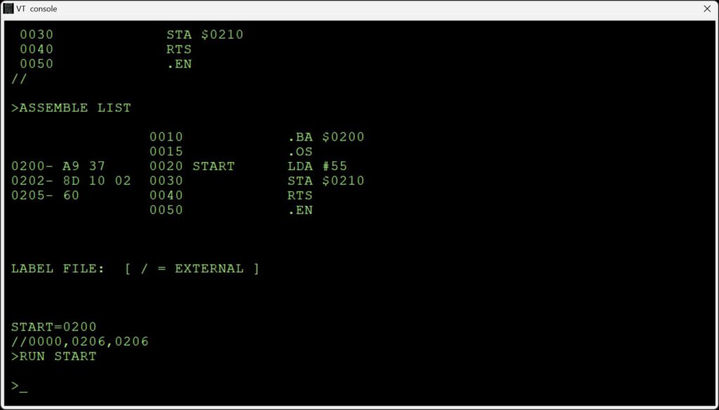
– Enter ASSM/TED via the warm start at 2003 (KIM-1) or B003 (SYM-1)
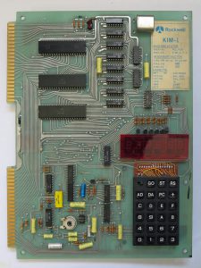
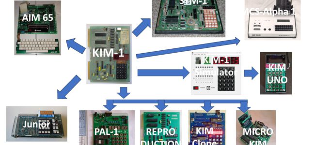
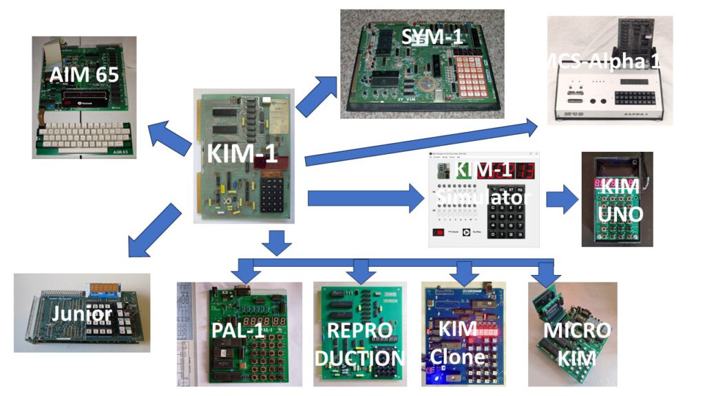
The KIM-1 is one of the first computer systems build around the 6502 microprocessor, somewhere in 1975.
The hardware and software concepts in the KIM-1 were reused in a number of systems created later.
Application and expansion connector
KIM-1 monitor software in ROMs 6430-002 and 6430-003
RRIOTs in 6530 (equivalent to 6532)
Bitbanged serial interface
6 multiplexed seven segment LEDs and hex keyboard
MOS Technology papertape format load and save
KIM-1 audiotape format
Over the years I have collected a ‘family’ of small computers with one or more concepts of the KIM-1, as shown in the figure above.
System          Connectors KIM-1 monitor Serial  LEDS + keypad Papertape KIM-1 audio RIOT
-----------------------------------------------------------------------------------------
KIM-1                X           X         X           X          X           X        X
SYM-1                X           X         X           X                      X        X
AIM 65               X                                                        X        X
MCS Alpha 1                                X           X                      X        X
Elektor Junior                             X           X                      X        X
KIM UNO                          X                     X          X                    X
Micro-KIM                        X         X           X          X                    X
KIM Clone                        X         X           X          X                    X
PAL-1                            X         X           X          X           X        X
MOS Reproduction     X           X         X           X          X           X        X
KIM-1 Simulator                  X         X           X          X                    X
-----------------------------------------------------------------------------------------
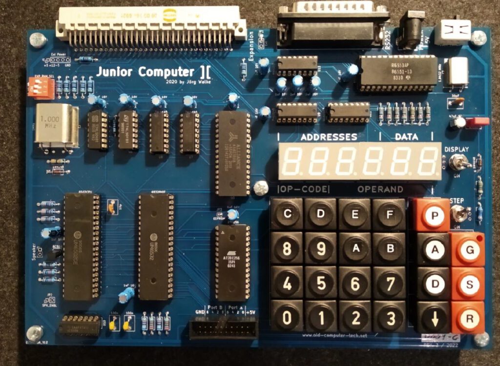
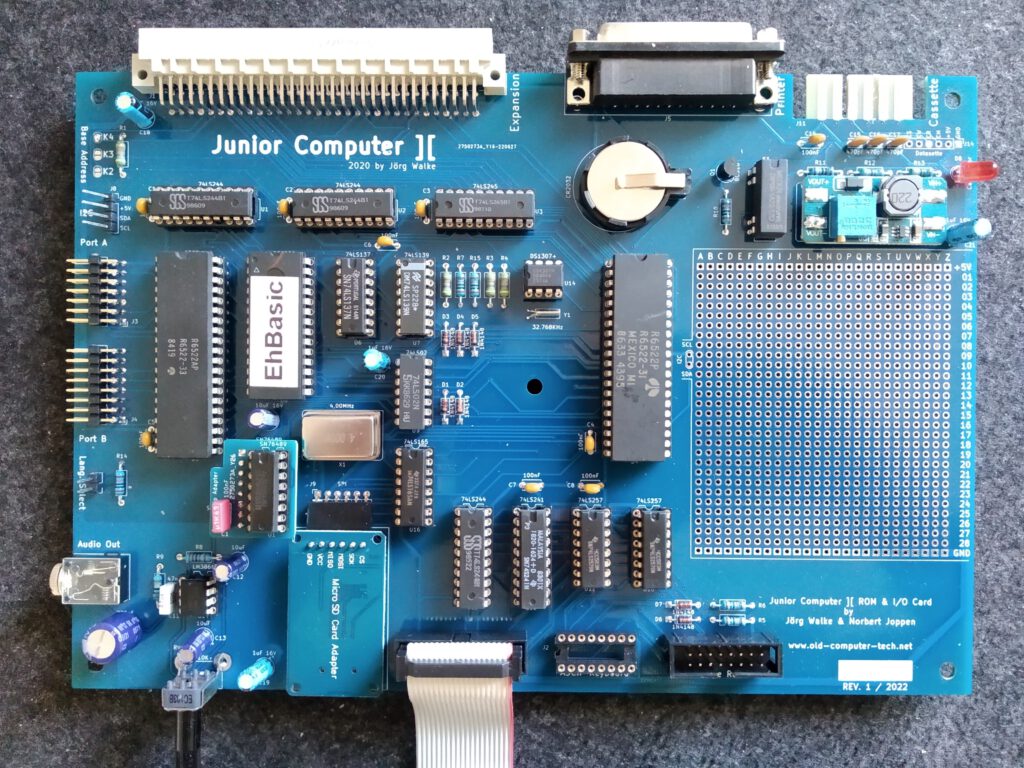
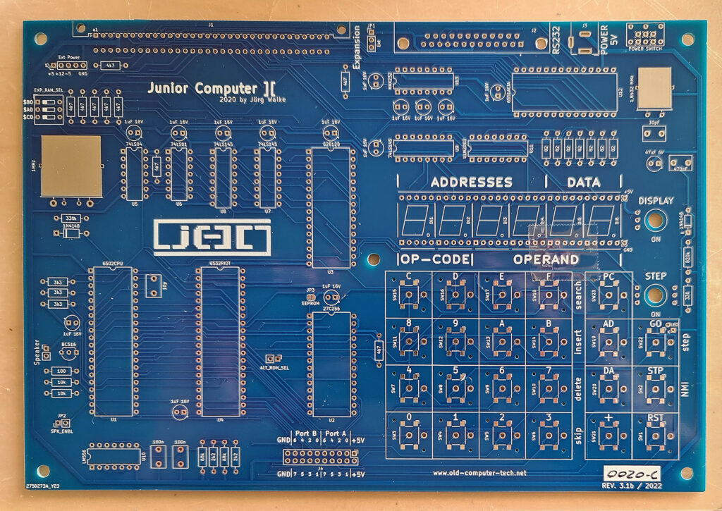
I reported some time ago about a new based upon the Elektor Junior design, by Jörg Walke, the Junior Computer ][.
Junior Computer ][ Main board
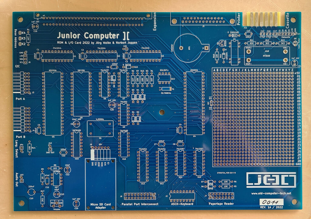
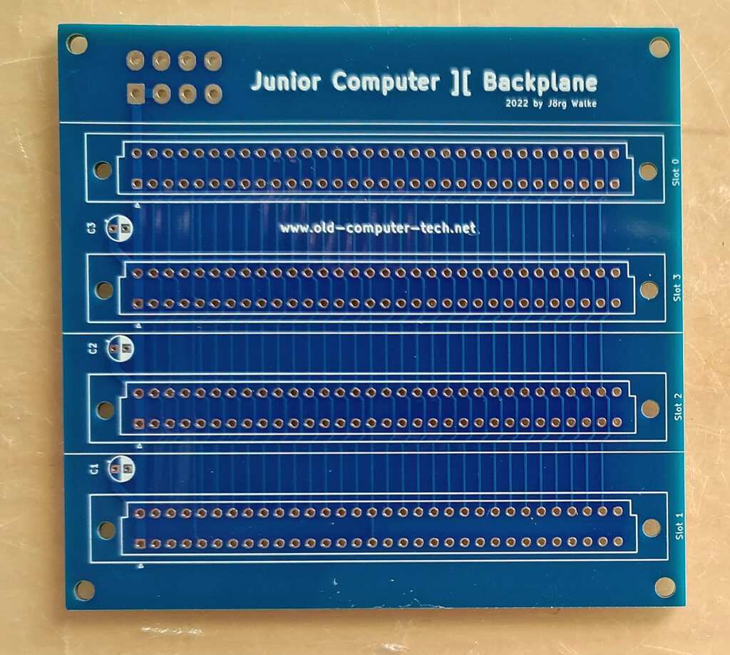
In the meantime the Junior ][ has grown up. A Bus card and an Interface card with a lot of functionality has been designed by Jörg, the software has also been updated with EHBasic and much more.
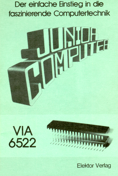
In May 1980 the DIY project Junior Computer was presented in the Elektor electronics magazine.
The little single-board computer was equipped with 1 KB ROM, in which the monitor program is located, 1 KB RAM (plus 128 bytes of RAM located in the 6532 RIOT), which, according to the authors, was more than enough at the time.
At the 40th anniversary of the computer, I decided to design a version with all features I wanted for the junior back in the 80s. The result is the Junior Computer ][ described here. It has 8KB ROM and a maximum of 128KB RAM. A additional serial RS232 interface and a simple sound output (as described in Junior Computer Book 2, from page 41) are also added. A 5V plug-in power supply with 2A should be sufficient. If external hardware needs to be supplied with voltage via the expansion connector, 3 Amps is recommended.
In order to be able to address the additional memory, the originally address decoding had to be extended. This is designed in such a way that the compatibility of the computer with the original Junior is preserved. An adaptation of the original monitor ROM to match the new memory location was not necessary.
Like its ancestor, the Junior Computer ][ can be expanded with external hardware via a 64-pin connection. The pin assignment oft he bus was largely retained.
In the new version, the 16 available port lines of the 6532 are available via 20-pin connector instead of a 31-pin connector.
The circuit changes mentioned here were made exclusively by me and expressly without the prior consent of the publisher Elektor, which is hopefully forgivable after 40 years. Of course, all rights to the original circuit design remain to Elektor and the authors.
Circuit diagrams, Gerber files, ROM images and other documents of the Junior Computer ][ (including this description) can be downloaded from https://old-computer-tech.net/downloads/ .
The computer and all its documents are published under the Creative Commons Attribution 4.0 license.
CPM-65, a CP/M-80 like operating system for 6502 based microcomputer
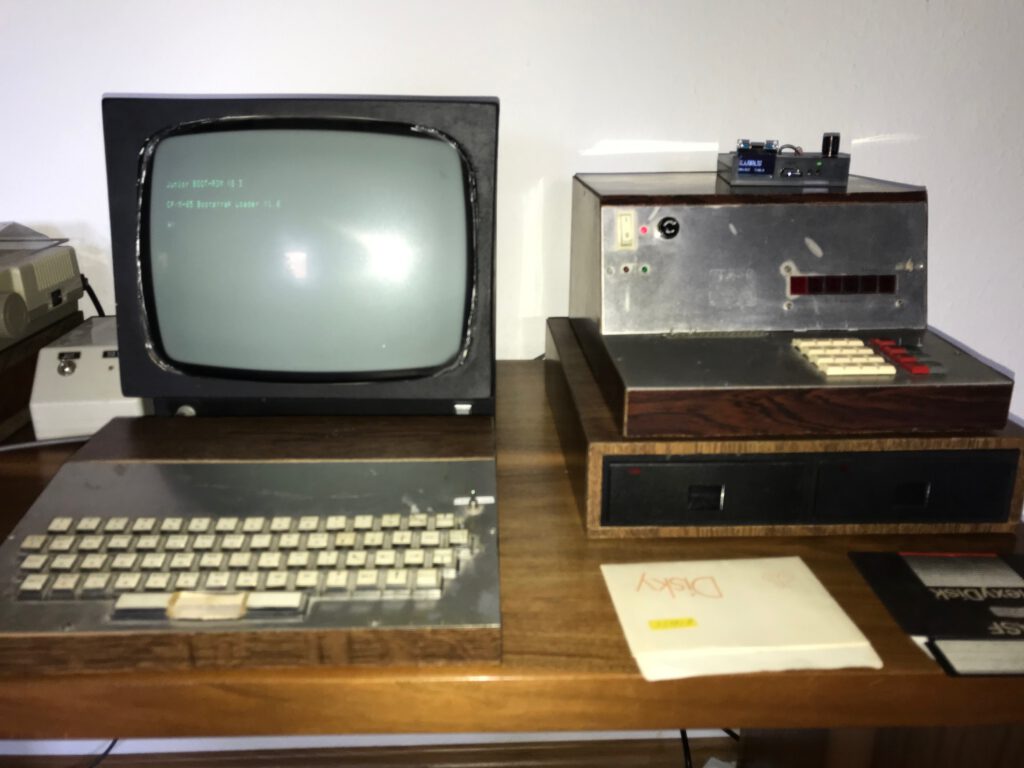
Dietrich Lausberg build a Junior long ago and expanded it to quite a system. He added hardware Elektor components, floppy and hard disk drives and wrote a CP/M inspired operating system, called CP/M-65. He still uses and maintains the system!
CPM-65, a CP/M-80 analogue operating system for 6502 based microcomputer
Dietrich Lausberg build a Junior long ago and expanded it to quite a system. He added hardware Elektor components, floppy and hard disk drives and wrote a CP/M inspired operating system, called CP/M-65. He still uses and maintains the system!
6532 I/O chip for the system timer (could be replaced by a 6522 or other)
minimal 1 Floppy drive
Serial I/O
The system is a heavily modified and expanded Elektor Junior Computer. For system components and memory map see below.
System Structure
CPM-65 consists of 3 layers:
BIOS Basic I/O system – currently 3 kB, could be reduced to 2kB by removing SCSI and I2C drivers. Drives can be A-H non consecutive.
BDOS Basic disc operating system – this is the CPM-65 kernal. Size 2 kB
CCP Console command program – a simple console which only allows to invoke CPM-65 programs. No resident commands. Size 1 kB
File and Disc Format
Filenames are CP/M-style d:filename.ext with d
Programs must have .COM as extension and are loaded to $0200 and started there.
The directory structure is CP/M-compatible and can be read with appropriate tools like CPMTOOLS
The Disc format is typically 40 tracks/ 8 sectors/ 256 byte/sector. It is defined in the BIOS. The BDOS operates on sector numbers. Maximum sector number is $800 blocks with $20 sectors = 65536 sectors á 256 bytes = 16 MBytes
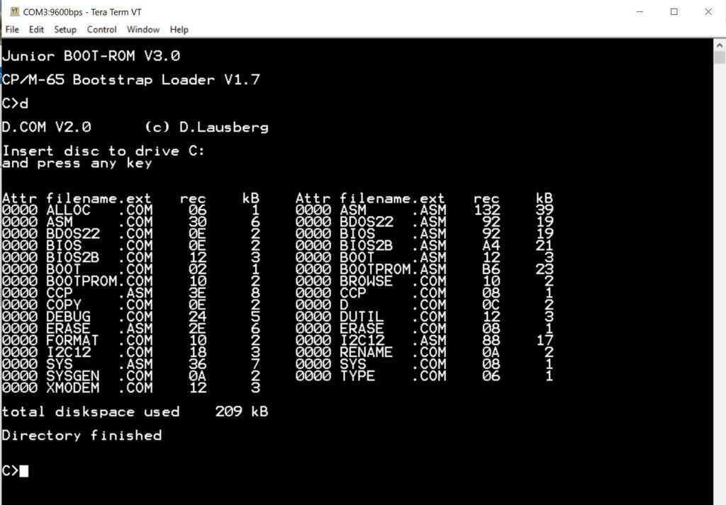
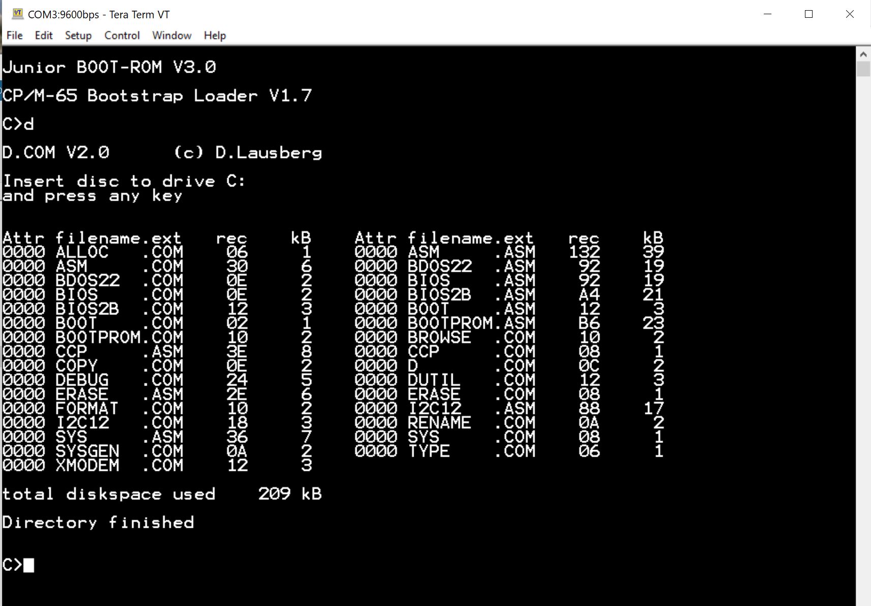
Available software (all written by Dietrich Lausberg)
Basic interpreter
Forth interpreter
Assembler for 6502
All software is supplied as assembler files to be assembled with the CPM-65 assembler.
Hardware
Dietrich Lausberg’s system now has:
Base Junior
Interface card
64k Universal Memorycard
8k RAM/EPROM card
Universal Disk Controller (Elektor Computing 6) for HD SCSI disk (SD card) and floppy disk
EPROMmer
Elekterminal
Modifications made to Elektor cards
The Junior basecard was mapped to 1K RAM $E000-$E3FF, RIOT at $F600-$F7FF, EPROM was converted to a 2716 and is at $F800-$FFFF
The Interface card is mapped 1K RAM at $E400-$E7FF, 2K RAM (6116 replacing a 2716) at $E800-$EFFF, the VIA 6522 at $F800-$F9FF.
The tape interface is removed.
The 64k RAM card from Elektor 83/3-60 (Universelle Speicherkarte) with 48 k RAM (6 x 6264) is mapped to $0000 – $BFFF.
The card has a modification, which allows the Elektor EPROMMER to take over $B000-$BFFF when present on the bus
The 8K RAM-EPROM card was modified to 4 x 6116 at $C000-$DFFF, 1K RAM $F000-$F3FF
All modifications in the adressing were done with the existing glue logic. I know, its a bit convoluted, but it has evolved over time – actually the last change is from 2021. The system works very stable. So the mapping does not violate the 6502 timing requrements.
The target always was to have as much consecutive RAM from zero page to HIMEM as possible. This is a bit CP/M style and makes it easy for the software to use as much RAM as it can grab until the CCP is met (cwhich is currently at $D800). CPM-65 has up to 53 kB transient memory. The largest program is BASIC, which easily assembles in the RAM to a 10 kB program with 26K to spare. Basic then has 45247 Bytes free.
Drives
A: and B: 2 x BASF 6108 40 Tracks double density
C: Gotek with Flashfloppy V3.32 from Keir Fraser emulating another 40 tracks DD drive
E: and F: SCSI drive SCSI2SD V5.1 by Michael McMaster configured to emulate 2 x 16 MB harddiscs
Serial interface
Serial 1200 – 9600 Baud TTY to ELEKTERMINAL (1200 Baud) or Terminal emulator (600 Baud). As emulator TeraTerm is ued especially for file transfer via Xmodem or a a self-written ELEKTERMINAL emulator. The emulator is necessary, because some of the software, most notably the FORTH screen editor needs the very specific ELEKTERMINAL control codes.
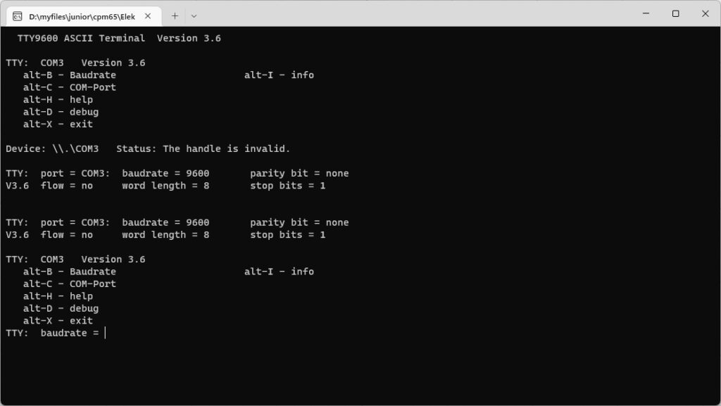
The program is written in Free Pascal and compiles in the LAZARUS PASCAL environment. The TTY5.EXE is verified to work under Windows 10 64 bit. No installation is needed, just invoke TTY5
Commands

   alt-B - Baudrate                      alt-I - info
   alt-C - COM-Port
   alt-H - help
   alt-D - debug
   alt-X - exit
Fixed parameters:
	word length = 8
	stop bits = 1
	parity bit = none
	flow = no
These parameters can be changed in the source code only.
ELEKTERMINAL commands
The ELEKTERMINAL uses the SF.F 96364 CRT Controller and some glue logic. The terminal displays 16 lines with 64 characters and interprets some ASCII command codes
Code 	Function
$08	Cursor <--
$09	Cursor -->
$0A	Cursor down
$0B	Cursor up
$0C	Home cursor + clear screen
$0D	Carriage Return
$1A	Clear current line
$1C	Home Cursor
$1D	Cursor to begin of line